EP0361927A1 - Pump control method and poppet valve therefor - Google Patents
Pump control method and poppet valve therefor Download PDFInfo
- Publication number
- EP0361927A1 EP0361927A1 EP89309900A EP89309900A EP0361927A1 EP 0361927 A1 EP0361927 A1 EP 0361927A1 EP 89309900 A EP89309900 A EP 89309900A EP 89309900 A EP89309900 A EP 89309900A EP 0361927 A1 EP0361927 A1 EP 0361927A1
- Authority
- EP
- European Patent Office
- Prior art keywords
- valve
- pump
- valve member
- fluid
- solenoid coil
- Prior art date
- Legal status (The legal status is an assumption and is not a legal conclusion. Google has not performed a legal analysis and makes no representation as to the accuracy of the status listed.)
- Granted
Links
Images

Classifications
-
- F—MECHANICAL ENGINEERING; LIGHTING; HEATING; WEAPONS; BLASTING
- F16—ENGINEERING ELEMENTS AND UNITS; GENERAL MEASURES FOR PRODUCING AND MAINTAINING EFFECTIVE FUNCTIONING OF MACHINES OR INSTALLATIONS; THERMAL INSULATION IN GENERAL
- F16K—VALVES; TAPS; COCKS; ACTUATING-FLOATS; DEVICES FOR VENTING OR AERATING
- F16K31/00—Actuating devices; Operating means; Releasing devices
- F16K31/02—Actuating devices; Operating means; Releasing devices electric; magnetic
- F16K31/06—Actuating devices; Operating means; Releasing devices electric; magnetic using a magnet, e.g. diaphragm valves, cutting off by means of a liquid
- F16K31/08—Actuating devices; Operating means; Releasing devices electric; magnetic using a magnet, e.g. diaphragm valves, cutting off by means of a liquid using a permanent magnet
- F16K31/082—Actuating devices; Operating means; Releasing devices electric; magnetic using a magnet, e.g. diaphragm valves, cutting off by means of a liquid using a permanent magnet using a electromagnet and a permanent magnet
-
- F—MECHANICAL ENGINEERING; LIGHTING; HEATING; WEAPONS; BLASTING
- F04—POSITIVE - DISPLACEMENT MACHINES FOR LIQUIDS; PUMPS FOR LIQUIDS OR ELASTIC FLUIDS
- F04B—POSITIVE-DISPLACEMENT MACHINES FOR LIQUIDS; PUMPS
- F04B49/00—Control, e.g. of pump delivery, or pump pressure of, or safety measures for, machines, pumps, or pumping installations, not otherwise provided for, or of interest apart from, groups F04B1/00 - F04B47/00
- F04B49/06—Control using electricity
- F04B49/065—Control using electricity and making use of computers
-
- F—MECHANICAL ENGINEERING; LIGHTING; HEATING; WEAPONS; BLASTING
- F04—POSITIVE - DISPLACEMENT MACHINES FOR LIQUIDS; PUMPS FOR LIQUIDS OR ELASTIC FLUIDS
- F04B—POSITIVE-DISPLACEMENT MACHINES FOR LIQUIDS; PUMPS
- F04B53/00—Component parts, details or accessories not provided for in, or of interest apart from, groups F04B1/00 - F04B23/00 or F04B39/00 - F04B47/00
- F04B53/10—Valves; Arrangement of valves
- F04B53/108—Valves characterised by the material
- F04B53/1082—Valves characterised by the material magnetic
-
- F—MECHANICAL ENGINEERING; LIGHTING; HEATING; WEAPONS; BLASTING
- F04—POSITIVE - DISPLACEMENT MACHINES FOR LIQUIDS; PUMPS FOR LIQUIDS OR ELASTIC FLUIDS
- F04B—POSITIVE-DISPLACEMENT MACHINES FOR LIQUIDS; PUMPS
- F04B7/00—Piston machines or pumps characterised by having positively-driven valving
- F04B7/0076—Piston machines or pumps characterised by having positively-driven valving the members being actuated by electro-magnetic means
-
- F—MECHANICAL ENGINEERING; LIGHTING; HEATING; WEAPONS; BLASTING
- F16—ENGINEERING ELEMENTS AND UNITS; GENERAL MEASURES FOR PRODUCING AND MAINTAINING EFFECTIVE FUNCTIONING OF MACHINES OR INSTALLATIONS; THERMAL INSULATION IN GENERAL
- F16H—GEARING
- F16H61/00—Control functions within control units of change-speed- or reversing-gearings for conveying rotary motion ; Control of exclusively fluid gearing, friction gearing, gearings with endless flexible members or other particular types of gearing
- F16H61/38—Control of exclusively fluid gearing
- F16H61/40—Control of exclusively fluid gearing hydrostatic
- F16H61/42—Control of exclusively fluid gearing hydrostatic involving adjustment of a pump or motor with adjustable output or capacity
- F16H61/431—Pump capacity control by electro-hydraulic control means, e.g. using solenoid valves
Definitions
- One previously proposed method of disabling a piston-in-cylinder module is to hold open mechanically the inlet valve to the cylinder of the module so that the fluid drawn into the cylinder on the inlet stroke is pumped back into the low-pressure inlet manifold throughout the delivery stroke rather than to the high-pressure delivery side of the pump.
- a pump having "n" cylinders and means to independently enable or disable each of the piston and cylinder modules could offer "n” stepped levels of displacement. It will be appreciated that with such an arrangement, the variations in displacement are fixed depending simply on the number of piston and cylinder modules which are utilised at any one time.
- the poppet valve 8 During each intake stroke of the piston, the poppet valve 8 is moved under the influence of fluid flow into the open position where it latches. In this position liquid can flow backwards and forwards through the annular passage defined between the bulbous head of the valve 8 and the outlet 7, the hydraulic liquid being pumped back into the low-pressure inlet manifold as the piston makes its discharge stroke with very little loss of energy compared to that which would have been transferred to the liquid had the valve 8 been closed.
Landscapes
- Engineering & Computer Science (AREA)
- General Engineering & Computer Science (AREA)
- Mechanical Engineering (AREA)
- Computer Hardware Design (AREA)
- Physics & Mathematics (AREA)
- Electromagnetism (AREA)
- Details Of Reciprocating Pumps (AREA)
- Reciprocating Pumps (AREA)
- Control Of Positive-Displacement Pumps (AREA)
- Electromagnetic Pumps, Or The Like (AREA)
- Valve Device For Special Equipments (AREA)
- Fluid-Driven Valves (AREA)
Abstract
Description
- This invention relates to a method for electrically controlling the actuation of a reciprocating fluid (i.e. gas or liquid) pump, preferably a pump with static pumping chambers and more preferably a multi-piston fluid pump. The invention also extends to an electrically selectable hydraulic poppet valve for employment in the method.
- Reciprocating multi-chamber fluid pumps are well known and generally comprise a plurality of static pumping chambers each equipped with a poppet valve to control inlet of fluid into the chamber (on an inlet stroke) for subsequent pressurisation therein on a discharge stroke. Common embodiments of reciprocating multi-chamber pump have a plurality of piston-in-cylinder modules disposed about an annular lobed cam, eccentric or swash plate, carried by a drive shaft. As the drive shaft is rotated to cause rotation of the lobed cam or eccentric, the piston-in-cylinder modules are sequentially operated to cause hydraulic fluid to be pumped from a low-pressure inlet manifold through the poppet valve in each module to a high-pressure delivery manifold. By enabling or disabling one or more of the pumping chambers (or modules), variable stepped changes in the displacement of the pump can be achieved.
- One previously proposed method of disabling a piston-in-cylinder module is to hold open mechanically the inlet valve to the cylinder of the module so that the fluid drawn into the cylinder on the inlet stroke is pumped back into the low-pressure inlet manifold throughout the delivery stroke rather than to the high-pressure delivery side of the pump. In this way, for example, a pump having "n" cylinders and means to independently enable or disable each of the piston and cylinder modules, could offer "n" stepped levels of displacement. It will be appreciated that with such an arrangement, the variations in displacement are fixed depending simply on the number of piston and cylinder modules which are utilised at any one time.
- Such previously proposed mechanical arrangements have significant disadvantages in that they have proved to be relatively slow and noisy in operation as well as being limited in the degree of displacement variation which can be achieved.
- One aim of the present invention is to obviate or mitigate the aforesaid disadvantages. A further aim is to provide a method for the real time control of the displacement of a multi-chamber reciprocating fluid pump having individually electrically controllable poppet valves serving as inlet valves to at least some of the pumping chambers.
- According to one aspect of the present invention a method of controlling the output of a reciprocating fluid pump having a plurality of pumping chambers each of which has an inlet valve with a valve member movable to an open limit condition to admit low pressure fluid to the chamber on an inlet stroke of the pump, and movable to a closed limit condition to prevent fluid again flowing past the valve member and to be ejected at high pressure from the chamber on a discharge stroke of the pump, and means to control the opening and closing of the valve member, is characterised in that electromagnetic means is provided for holding the valve member of at least one of the chambers in one of its limit conditions during at least part of a stroke of the pump in said at least one chamber.
- Preferably each pumping chamber is a piston-in-cylinder module and the electromagnetic means comprises a solenoid coil fixedly mounted in a casing of the valve and an annular permanent magnet surrounding the valve member, the magnet moving relative to the coil in the opening/closing direction of the valve member.
- Conveniently, electrical energisation of the solenoid coil is controlled by a microprocessor unit in response to at least one of output pressure of fluid and output displacement volume of fluid leaving the pump. Energisation of the solenoid coil can be used to move the valve member to its closed limit condition, de-energisation allowing the valve member to move under the influence of fluid flow-induced forces into its open limit condition.
- Preferably, the sealing surface of the valve member is formed on a bulbous head of generally elliptical shape with a part spherical area defining the sealing region, the head being connected to a tubular stem, and fluid flow in the open condition of the valve member being smooth and devoid of sharp transitions.
- In its valve aspect the invention specifies a valve element having an elongated hollow stem and associated bulbous head, a permanent magnet surrounding and being connected to the stem to move in the elongate direction of the stem. Desirably the hollow stem has internally chamfered ends and is made of non-ferromagnetic material. A second solenoid coil may be provided to draw the annular magnet away from the first solenoid coil and to latch the valve in the open limit condition.
- The method of the invention allows a reciprocating multi-chamber pump (usually of five or more piston-in-cylinder modules) to be controlled in real time to match a predetermined demand characteristic which can be varied smoothly over wide ranges. By sensing the actual operating characteristics of each chamber during each rotational cycle of the pump and comparing this with the predetermined demand characteristic during each cycle (or at (say) BDC (bottom dead centre) of the piston in a piston-in-cylinder module) the output of the pump can be accurately matched to what has previously been determined will be required.
- The predetermined demand characteristics can include pump displacement and noise emission.
- An embodiment of the present invention will now be described, by way of example, with reference to the accompanying drawings, in which:
- Figure 1 is a vertical sectional view of an electrically selectable poppet valve for a multi-piston hydraulic pump, and
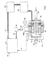
- Figure 2 is a schematic view of an axial piston pump incorporating poppet valves of the kind shown in Figure 1 together with control equipment for the several poppet valves for performing the control method of this invention.
- The left-hand half of Figure 1 illustrates the poppet valve in the closed position while the right-hand half illustrates the valve in the open position.
- Referring to Figure 1, a valve suitable for a multi-piston hydraulic pump (such as an axial piston or ring-cam hydraulic pump) comprises a steel valve shell which is adapted to be fixedly mounted within a
cylinder body 2 of the pump through the intermediary of avalve end cap 3 and associatedcap screws 4. - The valve shell 1 has a
bore 5 therethrough through which pumped hydraulic fluid can pass from a profiledinlet 6 to a profiledoutlet 7. The profiles of the inlet to and outlet from thebore 5 are calculated to result in low fluid drag on passage therethrough and the profiledoutlet 7 includes a valve seat 7a for apoppet valve 8 made of surface-hardened steel. - The
poppet valve 6 is of bulbous (i.e. part-elliptical) form and is securely attached by means of acap screw 9 to a rigid buthollow support 10. To ensure good sealing even if there is some misalignment of the bulbous head in theoutlet 7, the bulbous head can be given a part spherical area in the vicinity of the sealing region of the member which seals with the valve seat 7a. Thesupport 10 is, in turn, integrally connected to a non-ferromagnetic (e.g. phosphor bronze) flow tube 11 by means of a thin septum constituted by rigid arms 12 which are angularly spaced from each other to permit relatively unrestricted passage of hydraulic fluid into and out of the tube 11. The upstream and downstream ends of the flow tube 11 are internally chamfered at 11a and 11b respectively. - The flow tube 11 with its associated
poppet valve 8 is axially slidable relative to thevalve bore 5 between the two limit positions shown on the left and on the right. - An axially movable, bistable
magnetic latch 13 is housed within a chamber 13a defined within the valve shell 1. Thelatch 13 is fixedly connected to the flow tube 11 by means of aspring circlip 14 and surrounds the latter. - The
magnetic latch 13 is of annular form having acore 15 of a magnetic material such as bonded or sintered rare earth material or neodymium-boron. Thecore 15 is enclosed on its radially inner and outer sides byferromagnetic pole rings non-ferromagnetic guard rings 18 and 19 respectively. Thecore 15 is desirably magnetised in the radial direction (e.g. so that the inner cylindrical surface thereof is the South pole and the outer cylinder surface is the North pole). - The
latch 13 is axially movable within its chamber 12 in a bistable manner under the influence of upper and lowerelectromagnetic solenoid coils - On appropriate electrical energisation of
coil 20 or of both of thecoils magnetic latch 13 is attracted to theenergised coil 20 so that thepoppet valve 8 is moved into the closed or "enabled" position was shown in the left-hand side of Figure 1 when magnetic lines link theupper coil 20 and thecore 15 but is held in the open or "disabled" position as shown on the right-hand side of Figure 1 when magnetic flux lines link thelower coil 21 and thecore 15. In the closed position of the valve, hydraulic liquid flowing upwardly in the direction of thearrow 25 is pumped into the high-pressure delivery side of the pump via adischarge port 26. - During each intake stroke of the piston, the
poppet valve 8 is moved under the influence of fluid flow into the open position where it latches. In this position liquid can flow backwards and forwards through the annular passage defined between the bulbous head of thevalve 8 and theoutlet 7, the hydraulic liquid being pumped back into the low-pressure inlet manifold as the piston makes its discharge stroke with very little loss of energy compared to that which would have been transferred to the liquid had thevalve 8 been closed. - As the
poppet valve 6 and its associatedmagnetic latch 13 move into the open position, thelatch 13 can be made to contact a resilient end stop ring before it contacts thecoil 21 and its surrounding surfaces. Such a resilient end stop ring can be used to cushion movement of thelatch 13 into its fully open position. - The valve as described above has a response time which is fast enough so that it can be closed at the appropriate moment in a pumping cycle of a multi-piston hydraulic pump (e.g. a ring-cam pump) and this permits the pump to be operated with improved performance, particularly with respect to control of pump displacement.
- The
lower solenoid coil 21 augments the action of theupper coil 20 during the movement of thevalve 6 into its closed position, theupper coil 20 attracting thelatch 13 and thelower coil 21 repelling it. - Although a
lower solenoid coil 21 is shown in Figure 1 this can be dispensed with, and electromagnetic operation achieved with just the onecoil 20 to hold the valve member latched in the closed position. Latching in the open position is achieved by the creation of a closed "lower" flux loop through thecore 15 of the magnet and the adjacent part of the shell 1 of the valve. When thecoil 20 is energised the latching flux holding thevalve 8 open is diverted into a new circuit which includes thecoil 20 so that the closed "lower" flux loop is destroyed in favour of an "upper" flux loop that embraces thecore 15 and draws the annular magnet up towards thecoil 20. Return of the valve member 8-11 to its open condition will occur on the basis of liquid flow-induced forces when the piston commences its next inlet stroke if thesolenoid coil 20 is then deenergised (or energised with a polarity repelling the core 15). - By virtue of the present invention which involves the electrical control of the inlet valves of a reciprocating hydraulic pump, significant and advantageous consequences arise which have not hitherto been possible with pumps having mechanically controlled valves and this will now be described with reference to Figure 2.
- Figure 2 shows a
multi-piston pump 30 having a ring ofpistons 31 driven bycam 32 as a drivencam shaft 33 rotates. Eachpiston 31 reciprocates in itscylinder 34 under the influence of the rotatingcam 32, drawing hydraulic liquid into thecylinders 31 from alow pressure manifold 35 via an electromagnetically controlledvalve 36 of the kind shown in Figure 1 during each inlet stroke. At BDC eachpiston 31 reverses direction of movement to start its delivery stroke, and if therespective valve 36 is closed, the hydraulic liquid is forced through thedischarge port 26 into ahigh pressure duct 37. - Mounted on the
duct 37 is an output accumulator 38 (to smooth out pressure pulses in the discharge from the pump) and apressure measuring transducer 39. - In operation of the pump, a
micro-processor unit 40 is used to control the opening and closing of thevalves 36. A once-per-revolution" shaft trigger signal is generated on a line 41 (by atransducer 42 sensing passage of a "mark" 43 on the cam 32) and is fed to theunit 40 with a digital input online 44 related to pump output demand and a digital input online 45 from an analogue/digital converter 46 connected to thetransducer 39. - The
unit 40 provides a digital output online 47 which controls a bank ofsolenoid drivers 49 via an isolating stage 48 (which can contain opto-isolators and transistor drivers). - The
microprocessor control unit 40 could contain several built-in algorithms which enable the unit to compare the pump system demand characteristics with system feedback and which outputs a signal on actuation of a cylinder and which causes the next cylinder to reach BDC to become enabled should the system require its displacement of fluid. This algorithm would desirably be tempered with a maximum rate of change algorithm which would prevent sudden surges. Thus, the actual operating displacement characteristics of the pump system are electromagnetically modified in accordance with the desired demand displacement characteristics. The enabling pulse would then be sent to thesolenoid driver 49 after being timed by the noise algorithm in order to just close thevalve 36 of a module by the time thepiston 31 in that module reached BDC. In this way the shock wave generated by late valve closing is reduced. - The hardware illustrated in Figure 2 can operate for example in two different modes, a flow control mode and a pressure control mode.
- The
unit 40 keeps a running account of the displacement demand (from either a fixed level or an external input such as an operator joystick) and the displacement produced by thepump 30. At each cylinder enabling opportunity theunit 40 decides whether the demand foreseen at the time of maximum effectiveness of the current cylinder justifies its being enabled. This occurs if the displacement account will be at a deficit of more than half of a cylinder. Theaccumulator 36 is sized so that a half cylinder error will cause less than 10% variation in line pressure. This control method is, in itself, open loop since no feedback is used. Feedback can be applied by positioning a summing junction prior to thedemand input 44 of themicro-processor unit 40. - In this situation the
unit 40 attempts to maintain the required pressure on the output line irrespective of the demand function. What it is actually doing is trying to keep the accumulator volume as close to the zero error state as possible. To know the pumping requirements the system has to calculate the flow from the output to the load. This can be done by measuring the system pressure at two consecutive cylinder decision intervals. The change in pressure equates to a change in accumulator volume which indicates the displacement contribution from theaccumulator 36 to the system. The displacement delivered by thepump 30 during the time interval is calculated from the records of the previously enabled cylinders. The output flow is the sum of pump and accumulator flow (since the flow is incompressible for these purposes). - The output flow demand, the displacement from the committed cylinders and the displacement to the accumulator (to restore it to the zero error position) are then combined to allow a decision on whether to enable the current cylinder.
- The
microprocessor unit 40 can be equipped with different inputs including, for example: - 1. Pump system demand characteristics for example from a potentiometer, a throttle pedal (in the case of a pump used for vehicle drive), or a digital set-point.
- 2. Pump system feed back signals, for example from a motor speed sensor.
- 3. Noise sensor, for example an accelerometer, located on the pump casing.
- It will be readily appreciated from the above that, because of the ability to control the
valve 36 of each piston and cylinder module of a pump within every cycle of the pump, a pump, particularly a pump with a substantial number of cylinders, is capable of more or less infinite variation in displacement. This differs from the stepped type of variation possible in pumps heretofore. - It will, for example, be possible to programme the operation of a pump so that its output varies from cycle to cycle. Alternatively, a pump can be divided into a number of independently operable sections each comprising a plurality of cylinders. Each section can be independently controlled as to displacement and used for operating separate machines.
Claims (10)
Priority Applications (5)
| Application Number | Priority Date | Filing Date | Title |
|---|---|---|---|
| EP90915148A EP0494236B1 (en) | 1988-09-29 | 1990-09-27 | Improved fluid-working machine |
| AU65079/90A AU641438B2 (en) | 1988-09-29 | 1990-09-27 | Improved fluid-working machine |
| DE69024223T DE69024223T2 (en) | 1989-09-28 | 1990-09-27 | FLUID MACHINE |
| PCT/GB1990/001478 WO1991005163A1 (en) | 1988-09-29 | 1990-09-27 | Improved fluid-working machine |
| ZA907810A ZA907810B (en) | 1989-09-28 | 1990-09-28 | Fluid-working machine |
Applications Claiming Priority (2)
| Application Number | Priority Date | Filing Date | Title |
|---|---|---|---|
| GB888822901A GB8822901D0 (en) | 1988-09-29 | 1988-09-29 | Apparatus & method for controlling actuation of multi-piston pump &c |
| GB8822901 | 1988-09-29 |
Publications (2)
| Publication Number | Publication Date |
|---|---|
| EP0361927A1 true EP0361927A1 (en) | 1990-04-04 |
| EP0361927B1 EP0361927B1 (en) | 1994-07-27 |
Family
ID=10644469
Family Applications (1)
| Application Number | Title | Priority Date | Filing Date |
|---|---|---|---|
| EP89309900A Expired - Lifetime EP0361927B1 (en) | 1988-09-29 | 1989-09-28 | Pump control method and poppet valve therefor |
Country Status (9)
| Country | Link |
|---|---|
| US (2) | US5190446A (en) |
| EP (1) | EP0361927B1 (en) |
| JP (2) | JPH04501294A (en) |
| AU (1) | AU639213B2 (en) |
| DE (1) | DE68917066T2 (en) |
| GB (1) | GB8822901D0 (en) |
| NZ (1) | NZ230801A (en) |
| WO (1) | WO1990003519A1 (en) |
| ZA (1) | ZA897398B (en) |
Cited By (77)
| Publication number | Priority date | Publication date | Assignee | Title |
|---|---|---|---|---|
| US5259738A (en) * | 1988-09-29 | 1993-11-09 | University Of Edinburgh | Fluid-working machine |
| WO2001002715A1 (en) * | 1999-07-01 | 2001-01-11 | New Malone Company Limited | An external combustion engine |
| EP1423611A1 (en) * | 2001-09-06 | 2004-06-02 | U.S. Environmental Protection Agency | Fully-controlled, free-piston engine |
| WO2005106248A1 (en) * | 2004-03-30 | 2005-11-10 | Valeo Compressor Europe Gmbh | Stroke volume-variable compressor and method for adjusting the piston stroke in this compressor |
| WO2006090174A1 (en) * | 2005-02-26 | 2006-08-31 | Artemis Intelligent Power Limited | Valvetrain control arrangement |
| GB2427660A (en) * | 2005-06-29 | 2007-01-03 | Arctic Circle Ltd | A compressor with solenoid actuated capacity control inlet valves |
| WO2007088380A1 (en) | 2006-02-02 | 2007-08-09 | Artemis Intelligent Power Limited | Operating method for a hydraulic machine |
| WO2008009950A1 (en) | 2006-07-21 | 2008-01-24 | Artemis Intelligent Power Limited | Fluid power distribution and control system |
| WO2008012587A2 (en) | 2006-07-27 | 2008-01-31 | Artemis Intelligent Power Ltd | A digital hydraulic pump/motor torque modulation system and apparatus |
| WO2009003443A1 (en) * | 2007-07-03 | 2009-01-08 | Robert Bosch Gmbh | Valve-controlled hydraulic machine |
| EP2055942A1 (en) | 2007-11-01 | 2009-05-06 | Sauer-Danfoss ApS | Hydraulic system with supplement pump |
| EP2055946A1 (en) * | 2007-11-01 | 2009-05-06 | Sauer-Danfoss ApS | Operating mehtod for fluid working machine |
| WO2009153605A1 (en) * | 2008-06-20 | 2009-12-23 | Artemis Intelligent Power Limited | Fluid working machines and methods |
| WO2009158147A1 (en) * | 2008-06-27 | 2009-12-30 | Cameron International Corporation | Systems and devices including valves coupled to electric devices and methods of making, using, and operating the same |
| WO2010073040A1 (en) | 2008-12-22 | 2010-07-01 | Artemis Intelligent Power Limited | Valve assembly |
| EP2239463A1 (en) | 2009-04-07 | 2010-10-13 | Artemis Intelligent Power Limited | Fluid working machine and method of operating a fluid working machine |
| EP2246565A1 (en) * | 2009-04-28 | 2010-11-03 | Sauer-Danfoss GmbH & Co. OHG | Method of operating a fluid working machine |
| WO2010141733A1 (en) * | 2009-06-03 | 2010-12-09 | Eaton Corporation | Fluid device with magnetic latching valves |
| WO2011018663A2 (en) | 2009-08-11 | 2011-02-17 | New Malone Company Limited | Closed loop thermodynamic machine |
| EP2322802A1 (en) | 2009-11-13 | 2011-05-18 | Artemis Intelligent Power Limited | Electronically controlled valve |
| WO2011104549A2 (en) | 2010-02-23 | 2011-09-01 | Artemis Intelligent Power Limited | Fluid-working machine and method of operating a fluid-working machine |
| WO2011104545A2 (en) | 2010-02-23 | 2011-09-01 | Artemis Intelligent Power Limited | Method of measuring a property of entrained gas in a hydraulic liquid and fluid-working machine |
| WO2011104544A2 (en) | 2010-02-23 | 2011-09-01 | Artemis Intelligent Power Limited | Variable displacement radial piston fluid working machine |
| WO2011104546A2 (en) | 2010-02-23 | 2011-09-01 | Artemis Intelligent Power Limited | Fluid working machine and method of operating fluid working machine |
| GB2480683A (en) * | 2010-05-28 | 2011-11-30 | Artemis Intelligent Power Ltd | A method and apparatus for operating a renewable energy extraction device |
| WO2011147996A2 (en) | 2010-05-28 | 2011-12-01 | Artemis Intelligent Power Limited | Method and apparatus for extracting energy from a fluctuating energy flow from a renewable energy source |
| WO2012022953A1 (en) | 2010-08-17 | 2012-02-23 | Artemis Intelligent Power Limited | Ring cam and fluid-working machine including ring cam |
| WO2012022954A1 (en) | 2010-08-17 | 2012-02-23 | Artemis Intelligent Power Limited | Ring cam and fluid-working machine including ring cam |
| WO2012022924A1 (en) | 2010-08-17 | 2012-02-23 | Artemis Intelligent Power Limited | Fluid-working machine with multi-lobe ring cam |
| WO2012022952A1 (en) | 2010-08-17 | 2012-02-23 | Artemis Intelligent Power Limited | Ring cam and fluid-working machine including ring cam |
| US8192175B2 (en) | 2007-11-01 | 2012-06-05 | Sauer-Danfoss Aps | Method of controlling a cyclically commutated hydraulic pump |
| WO2012073502A1 (en) | 2010-11-30 | 2012-06-07 | Mitsubishi Heavy Industries, Ltd. | Renewable energy extraction device such as a wind turbine with hydraulic transmission |
| WO2012073390A1 (en) | 2010-11-30 | 2012-06-07 | Mitsubishi Heavy Industries, Ltd. | Renewable energy extraction device such as wind turbine with hydraulic transmission |
| US8197223B2 (en) | 2007-11-01 | 2012-06-12 | Sauer-Danfoss Aps | Method of operating a fluid working machine |
| US8197224B2 (en) | 2007-11-01 | 2012-06-12 | Sauer-Danfoss Aps | Method of operating a fluid working machine |
| WO2013005258A1 (en) | 2011-07-06 | 2013-01-10 | Mitsubishi Heavy Industries, Ltd. | Energy extraction device with electrical generator and method of operating energy extraction device electrical generator |
| WO2013005259A2 (en) | 2011-07-06 | 2013-01-10 | Mitsubishi Heavy Industries, Ltd. | Energy extraction device, group of energy extraction devices and operating methods |
| WO2013018146A1 (en) | 2011-08-03 | 2013-02-07 | Mitsubishi Heavy Industries, Ltd. | Cylinder assembly for fluid working machine |
| EP2581271A1 (en) * | 2008-05-01 | 2013-04-17 | Multimatic Inc. | Vehicle auxiliary hydraulic system |
| WO2013080397A1 (en) | 2011-11-30 | 2013-06-06 | Mitsubishi Heavy Industries, Ltd. | Power generating apparatus of a renewable energy type and operation method thereof |
| CN103174627A (en) * | 2011-12-20 | 2013-06-26 | 诺沃皮尼奥内有限公司 | Methods and devices for constructively using the pressure pulsations in reciprocating compressors installations |
| WO2013114436A1 (en) | 2012-01-31 | 2013-08-08 | Mitsubishi Heavy Industries, Ltd. | Method of controlling a hydraulic machine to reduce torque ripple and/or bearing side load |
| WO2013114437A1 (en) | 2012-01-31 | 2013-08-08 | Mitsubishi Heavy Industries, Ltd. | Hydraulic transmission comprising variable displacement pump or motor operable with discontinuous range of displacements |
| WO2013118180A1 (en) | 2012-02-09 | 2013-08-15 | Mitsubishi Heavy Industries, Ltd. | Fluid working machine with valve actuation |
| WO2013118181A1 (en) | 2012-02-09 | 2013-08-15 | Mitsubishi Heavy Industries, Ltd. | Fluid working machine with valve actuation |
| WO2013118182A1 (en) | 2012-02-09 | 2013-08-15 | Mitsubishi Heavy Industries, Ltd. | Annular valve |
| WO2013183081A1 (en) | 2012-06-05 | 2013-12-12 | Mitsubishi Heavy Industries, Ltd. | Method of synchronising a generator drive with an alternating current electrical network |
| WO2014006663A1 (en) | 2012-07-06 | 2014-01-09 | Mitsubishi Heavy Industries, Ltd. | Power generating apparatus and a method of operating a pump/motor of a power generating apparatus |
| WO2014024232A1 (en) | 2012-08-10 | 2014-02-13 | Mitsubishi Heavy Industries, Ltd. | Poppet valve |
| WO2014054072A1 (en) | 2012-10-04 | 2014-04-10 | Mitsubishi Heavy Industries, Ltd. | Power generating apparatus of a renewable energy type having hydraulic pump also operable in motoring mode |
| DE102012025197A1 (en) | 2012-12-27 | 2014-07-03 | Robert Bosch Gmbh | Device for observing actual condition of digital adjustable hydraulic machine, has determining unit for determining actual condition of hydraulic machine and located on base based on evaluation result of evaluating device |
| WO2014132089A1 (en) | 2013-03-01 | 2014-09-04 | Artemis Intelligent Power Limited | Valve unit a fluid working machine comprising a valve unit |
| US8905732B2 (en) | 2007-11-01 | 2014-12-09 | Danfoss Power Solutions Aps | Fluid working machine |
| EP2851586A1 (en) | 2013-09-18 | 2015-03-25 | MITSUBISHI HEAVY INDUSTRIES, Ltd. | Hydraulic transmission |
| EP2851562A1 (en) | 2013-09-18 | 2015-03-25 | Mitsubishi Heavy Industries, Ltd. | Hydraulic transmission |
| EP2851585A1 (en) | 2013-09-18 | 2015-03-25 | Artemis Intelligent Power Limited | Hydraulic transmission and method of controlling hydraulic transmission |
| WO2015040360A1 (en) | 2013-09-18 | 2015-03-26 | Artemis Intelligent Power Limited | Hydraulic transmission |
| US9033309B2 (en) | 2008-10-29 | 2015-05-19 | Sauer Danfoss Aps | Valve actuator |
| WO2016128914A1 (en) * | 2015-02-11 | 2016-08-18 | Dott. Ing. Mario Cozzani S.R.L. | Flow control actuator for reciprocating compressors |
| US9488163B2 (en) | 2009-08-14 | 2016-11-08 | Artemis Intelligent Power Limited | Fluid control system |
| US20160356160A1 (en) | 2013-06-18 | 2016-12-08 | Artemis Intelligent Power Ltd. | Fluid working machine |
| EP3121444A1 (en) | 2015-07-24 | 2017-01-25 | Artemis Intelligent Power Limited | Fluid working machine and method of operating a fluid working machine |
| WO2017033015A1 (en) | 2015-08-25 | 2017-03-02 | Artemis Intelligent Power Limited | The measurement and use of hydraulic stiffness properties of hydraulic apparatus |
| WO2017122024A1 (en) * | 2016-01-15 | 2017-07-20 | Artemis Intelligent Power Limited | Hydraulic apparatus comprising synthetically commutated machine, and operating method |
| US9739266B2 (en) | 2010-02-23 | 2017-08-22 | Artemis Intelligent Power Limited | Fluid-working machine and method of operating a fluid-working machine |
| US20170306936A1 (en) * | 2014-10-13 | 2017-10-26 | Danfoss Power Solutions Gmbh & Co. Ohg | Controller for hydraulic pump |
| EP3290695A1 (en) | 2016-08-12 | 2018-03-07 | Artemis Intelligent Power Limited | Valve for fluid working machine, fluid working machine and method of operation |
| EP3351827A1 (en) | 2017-01-20 | 2018-07-25 | Artemis Intelligent Power Limited | Hydrostatic transmission for vehicle |
| US10180135B2 (en) | 2014-09-30 | 2019-01-15 | Artemis Intelligent Power Limited | Industrial system with synthetically commutated variable displacement fluid working machine |
| EP3450312A1 (en) | 2017-09-04 | 2019-03-06 | Artemis Intelligent Power Limited | Hydraulic multi-rotor aerial vehicle |
| EP3486482A1 (en) | 2017-11-17 | 2019-05-22 | Artemis Intelligent Power Limited | Measuring hydraulic fluid pressure in a fluid-working machine |
| EP3514378A1 (en) | 2018-01-19 | 2019-07-24 | Artemis Intelligent Power Limited | Displacement of an object with hydraulic actuators |
| CN111094820A (en) * | 2017-09-07 | 2020-05-01 | 阿尔特弥斯智能动力有限公司 | Valve assembly |
| EP3674546A1 (en) | 2018-12-28 | 2020-07-01 | Artemis Intelligent Power Limited | Valve timing in electronically commutated hydraulic machine |
| US10738757B2 (en) | 2015-12-04 | 2020-08-11 | Regetns of the University of Minnesota | Variable displacement pump-motor |
| WO2021069929A1 (en) | 2019-10-09 | 2021-04-15 | Synchrostor Limited | Apparatus and methods for the storage of energy as heat |
| WO2022234476A3 (en) * | 2021-05-05 | 2023-01-05 | Bravotech Holding B.V. | Liquid displacing device and a non-return valve |
Families Citing this family (64)
| Publication number | Priority date | Publication date | Assignee | Title |
|---|---|---|---|---|
| DE4401073A1 (en) * | 1994-01-15 | 1995-07-20 | Rexroth Mannesmann Gmbh | Motor vehicle fuel pump |
| WO1995025892A2 (en) * | 1994-03-21 | 1995-09-28 | Sapphire Engineering, Inc. | Electro-magnetically operated valve |
| US5605317A (en) * | 1994-03-21 | 1997-02-25 | Sapphire Engineering, Inc. | Electro-magnetically operated valve |
| US5456581A (en) * | 1994-08-12 | 1995-10-10 | The United States Of America As Represented By The Secretary Of The Navy | Control system for a multi-piston pump with solenoid valves for the production of constant outlet pressure flow |
| US6047557A (en) * | 1995-06-07 | 2000-04-11 | Copeland Corporation | Adaptive control for a refrigeration system using pulse width modulated duty cycle scroll compressor |
| US6206652B1 (en) | 1998-08-25 | 2001-03-27 | Copeland Corporation | Compressor capacity modulation |
| JP3905282B2 (en) * | 2000-04-18 | 2007-04-18 | トヨタ自動車株式会社 | High pressure pump |
| JP3851056B2 (en) * | 2000-04-18 | 2006-11-29 | トヨタ自動車株式会社 | High pressure pump |
| US6988599B2 (en) | 2000-12-07 | 2006-01-24 | Visteon Global Technologies, Inc. | Compressible fluid strut |
| DE60109417T2 (en) | 2000-12-07 | 2006-04-13 | Visteon Global Technologies, Inc., Dearborn | SUSPENSION SYSTEM FOR ONE VEHICLE |
| US6651545B2 (en) | 2001-12-13 | 2003-11-25 | Caterpillar Inc | Fluid translating device |
| US6681571B2 (en) | 2001-12-13 | 2004-01-27 | Caterpillar Inc | Digital controlled fluid translating device |
| GB0221165D0 (en) * | 2002-09-12 | 2002-10-23 | Artemis Intelligent Power Ltd | Fluid-working machine and operating method |
| GB0407297D0 (en) * | 2004-03-31 | 2004-05-05 | Caldwell N J | Fluid working machine with displacement control |
| DE102004022111A1 (en) * | 2004-05-05 | 2005-11-24 | Robert Bosch Gmbh | Piston pump with actively operable closure element |
| WO2006055978A1 (en) | 2004-11-22 | 2006-05-26 | Bosch Rexroth Corporation | Hydro-electric hybrid drive system for motor vehicle |
| US7793496B2 (en) * | 2004-11-22 | 2010-09-14 | William Hugh Salvin Rampen | Infinitely variable transmission hydraulic hybrid for on and off highway vehicles |
| US7628240B2 (en) * | 2006-03-21 | 2009-12-08 | Sauer-Danfoss, Inc. | Fluid transmission with improved traction control |
| DE102006041087A1 (en) * | 2006-09-01 | 2008-03-06 | Robert Bosch Gmbh | Control device for a hydraulic piston engine with variable volume flow |
| JP4994455B2 (en) | 2006-09-08 | 2012-08-08 | アルテミス インテリジェント パワー リミティド | Fluid working machine and valve configuration |
| US8157538B2 (en) | 2007-07-23 | 2012-04-17 | Emerson Climate Technologies, Inc. | Capacity modulation system for compressor and method |
| US8469677B1 (en) * | 2007-10-01 | 2013-06-25 | Sauer-Danfoss Inc. | Check valve pump with electric bypass valve |
| EP2055950B1 (en) * | 2007-11-01 | 2017-04-12 | Danfoss Power Solutions Aps | Method of controlling a cyclically commutated hydraulic pump |
| US8074450B2 (en) * | 2008-08-13 | 2011-12-13 | General Electric Company | Wind energy system with fluid-working machine with non-symmetric actuation |
| AU2009290641A1 (en) | 2008-09-09 | 2010-03-18 | Artemis Intelligent Power Limited | Valve assemblies |
| ES2623055T3 (en) | 2009-01-27 | 2017-07-10 | Emerson Climate Technologies, Inc. | System and discharge method for a compressor |
| EP2211058A1 (en) | 2009-01-27 | 2010-07-28 | Sauer-Danfoss ApS | Hydraulic pump |
| JP5554825B2 (en) * | 2009-03-16 | 2014-07-23 | アルテミス インテリジェント パワー リミティド | Electronic control valve |
| WO2010115019A1 (en) | 2009-04-02 | 2010-10-07 | Husco International, Inc. | Fluid working machine with cylinders coupled to split exterior ports by electrohydraulic valves |
| US8096117B2 (en) | 2009-05-22 | 2012-01-17 | General Compression, Inc. | Compressor and/or expander device |
| US8454321B2 (en) | 2009-05-22 | 2013-06-04 | General Compression, Inc. | Methods and devices for optimizing heat transfer within a compression and/or expansion device |
| US20120189467A1 (en) * | 2009-07-23 | 2012-07-26 | Andreas Allenspach | Method for Controlling Delivery Quantity, and Reciprocating Compressor Having Delivery Quantity Control |
| DE102009036346A1 (en) * | 2009-08-06 | 2011-02-10 | Robert Bosch Gmbh | Hydraulic system with a hydrostatic piston machine |
| DE102009041061A1 (en) | 2009-09-10 | 2011-08-04 | Robert Bosch GmbH, 70469 | Electromagnetic operated valve e.g. seat slide valve, for operation of hydraulic digital displacement unit machine, has circuit board formed with valve as integral component and manufactured in hybrid technology |
| AU2010338399B2 (en) * | 2009-12-17 | 2016-01-28 | Wrightsolar Ltd | Pressure enhancing device |
| WO2011075813A1 (en) | 2009-12-23 | 2011-06-30 | Husky Injection Molding Systems Ltd. | Injection molding system having a digital displacement pump |
| EP2516952A2 (en) | 2009-12-24 | 2012-10-31 | General Compression Inc. | Methods and devices for optimizing heat transfer within a compression and/or expansion device |
| US8534687B2 (en) | 2010-07-05 | 2013-09-17 | Fluid Ride Ltd. | Suspension strut for a vehicle |
| US20120045327A1 (en) * | 2010-08-17 | 2012-02-23 | Artemis Intelligent Power Limited | Fluid-Working Machine with Multi-Lobe Ring Cam |
| US8535418B2 (en) * | 2010-11-22 | 2013-09-17 | General Electric Company | Gaseous byproduct removal from synthesis gas |
| JP5383714B2 (en) | 2010-11-30 | 2014-01-08 | 三菱重工業株式会社 | Wind power generator and tidal current power generator |
| KR101282540B1 (en) | 2010-11-30 | 2013-07-04 | 미츠비시 쥬고교 가부시키가이샤 | Wind turbine generator |
| AU2011338574B2 (en) | 2010-12-07 | 2015-07-09 | General Compression, Inc. | Compressor and/or expander device with rolling piston seal |
| US8997475B2 (en) | 2011-01-10 | 2015-04-07 | General Compression, Inc. | Compressor and expander device with pressure vessel divider baffle and piston |
| US8572959B2 (en) | 2011-01-13 | 2013-11-05 | General Compression, Inc. | Systems, methods and devices for the management of heat removal within a compression and/or expansion device or system |
| CA2824798A1 (en) | 2011-01-14 | 2012-07-19 | General Compression, Inc. | Compressed gas storage and recovery system and method of operation |
| US9200648B2 (en) | 2011-01-24 | 2015-12-01 | Purdue Research Foundation | Fluid control valve systems, fluid systems equipped therewith, and methods of using |
| DE102011115181A1 (en) | 2011-09-28 | 2013-03-28 | Robert Bosch Gmbh | Valve-controlled hydraulic machine has high-pressure valve arrangement that is actively switched and associated cylinder-piston units that are operable in fragmentary mode in which valve arrangement is closed during total stroke |
| DE102011115665A1 (en) | 2011-09-29 | 2013-04-04 | Robert Bosch Gmbh | Valve-controlled hydraulic machine e.g. hydraulic pump has cylinder-piston units that are operated in optimal mode, and are disabled immediately after passing through dead center, and activated during majority of total stroke |
| US8387375B2 (en) | 2011-11-11 | 2013-03-05 | General Compression, Inc. | Systems and methods for optimizing thermal efficiency of a compressed air energy storage system |
| US8522538B2 (en) | 2011-11-11 | 2013-09-03 | General Compression, Inc. | Systems and methods for compressing and/or expanding a gas utilizing a bi-directional piston and hydraulic actuator |
| US9574582B2 (en) | 2012-04-23 | 2017-02-21 | Fluid Ride, Ltd. | Hydraulic pump system and method of operation |
| CN102705191B (en) * | 2012-06-01 | 2015-09-23 | 沈如华 | The mill base quantitative supply device of colour mixer |
| US10125752B1 (en) * | 2012-07-19 | 2018-11-13 | Hydro-Gear Limited Partnership | Hydraulic motor |
| JP5993291B2 (en) * | 2012-11-27 | 2016-09-14 | 日立オートモティブシステムズ株式会社 | Variable displacement pump |
| WO2015112025A1 (en) | 2014-01-27 | 2015-07-30 | Diinef As | Hydraulic machine valve displacement |
| NO342168B1 (en) | 2016-11-04 | 2018-04-09 | Diinef As | A method for controlling torque equilibrium of a hydraulic motor |
| US11428314B2 (en) * | 2016-12-20 | 2022-08-30 | Kinetics Drive Solutions Inc. | Hydrostatic drive system with variable vibration damper |
| DK179314B1 (en) * | 2017-02-08 | 2018-04-30 | Steeper Energy Aps | Pressurization system for high pressure treatment system |
| DE102018117949A1 (en) * | 2018-07-25 | 2020-01-30 | Putzmeister Engineering Gmbh | Hydraulic system and method for controlling a hydraulic system |
| CN112112776A (en) * | 2019-06-04 | 2020-12-22 | 阿尔特弥斯智能动力有限公司 | Hydraulic machine and system |
| DE102020110002A1 (en) | 2020-04-09 | 2021-10-14 | Rheinisch-Westfälische Technische Hochschule (Rwth) Aachen | Arrangement of a work system for performing work by means of a pressurized hydraulic fluid and a pumping device |
| US11339885B1 (en) * | 2021-03-08 | 2022-05-24 | O2 Air-Sea, Llc | Oxygen generation check valve device |
| GB2618342A (en) | 2022-05-03 | 2023-11-08 | Domin Fluid Power Ltd | A hydraulic device and a hydraulic system for controlling a hydraulic actuator |
Citations (6)
| Publication number | Priority date | Publication date | Assignee | Title |
|---|---|---|---|---|
| CH288540A (en) * | 1948-12-23 | 1953-01-31 | Elmeg | Device with an electromagnetically driven pump. |
| US2785638A (en) * | 1954-04-08 | 1957-03-19 | Clifford B Moller | Force pump for slurries |
| EP0084070A1 (en) * | 1982-01-15 | 1983-07-27 | Polaroid Corporation | Pressure equalization pumping system |
| EP0102780A1 (en) * | 1982-08-12 | 1984-03-14 | Inoue-Japax Research Incorporated | Fluid pumping system |
| DE3312054A1 (en) * | 1983-04-02 | 1984-10-11 | Gebrüder Sulzer AG, Winterthur | Reversing valve controlling the through-flow of a pressure medium |
| WO1987005981A1 (en) * | 1986-03-26 | 1987-10-08 | Robert Bosch Gmbh | Magnetic valve |
Family Cites Families (13)
| Publication number | Priority date | Publication date | Assignee | Title |
|---|---|---|---|---|
| US2431769A (en) * | 1943-04-30 | 1947-12-02 | Parker Appliance Co | Quick opening check valve assembly |
| US3529806A (en) * | 1967-09-01 | 1970-09-22 | James A Kozel | Solenoid valve |
| NL145020B (en) * | 1969-10-30 | 1975-02-17 | Stork Jaffa Nv Maschf | PUMP OR MOTOR. |
| US3679328A (en) * | 1970-03-27 | 1972-07-25 | Applied Power Ind Inc | Variable pressure sensitive pump |
| US3712758A (en) * | 1970-09-10 | 1973-01-23 | Int Harvester Co | Variable displacement pump |
| US4241714A (en) * | 1979-06-25 | 1980-12-30 | General Motors Corporation | Solenoid valve controlled fuel injection pump |
| DE8322570U1 (en) * | 1983-08-05 | 1985-01-17 | Robert Bosch Gmbh, 7000 Stuttgart | PRESSURE REGULATOR |
| US4541394A (en) * | 1985-01-07 | 1985-09-17 | Ford Motor Company | Fuel injection pump |
| DE3622405A1 (en) * | 1985-07-03 | 1987-01-08 | Minolta Camera Kk | ELECTROSTATIC PHOTOCOPYER |
| US4825904A (en) * | 1988-04-18 | 1989-05-02 | Pneumo Abex Corporation | Two position flow control valve assembly with position sensing |
| GB8822901D0 (en) * | 1988-09-29 | 1988-11-02 | Mactaggart Scot Holdings Ltd | Apparatus & method for controlling actuation of multi-piston pump &c |
| US5110087A (en) * | 1990-06-25 | 1992-05-05 | Borg-Warner Automotive Electronic & Mechanical Systems Corporation | Variable force solenoid hydraulic control valve |
| US5088520A (en) * | 1991-05-20 | 1992-02-18 | South Bend Controls, Inc. | Modular solenid valve |
-
1988
- 1988-09-29 GB GB888822901A patent/GB8822901D0/en active Pending
-
1989
- 1989-09-27 NZ NZ230801A patent/NZ230801A/en unknown
- 1989-09-28 ZA ZA897398A patent/ZA897398B/en unknown
- 1989-09-28 US US07/671,827 patent/US5190446A/en not_active Expired - Lifetime
- 1989-09-28 DE DE68917066T patent/DE68917066T2/en not_active Expired - Lifetime
- 1989-09-28 AU AU44990/89A patent/AU639213B2/en not_active Expired
- 1989-09-28 WO PCT/GB1989/001146 patent/WO1990003519A1/en unknown
- 1989-09-28 JP JP1511380A patent/JPH04501294A/en active Pending
- 1989-09-28 EP EP89309900A patent/EP0361927B1/en not_active Expired - Lifetime
-
1990
- 1990-09-27 JP JP90513940A patent/JPH05503335A/en active Pending
- 1990-09-27 US US07/854,653 patent/US5259738A/en not_active Expired - Lifetime
Patent Citations (6)
| Publication number | Priority date | Publication date | Assignee | Title |
|---|---|---|---|---|
| CH288540A (en) * | 1948-12-23 | 1953-01-31 | Elmeg | Device with an electromagnetically driven pump. |
| US2785638A (en) * | 1954-04-08 | 1957-03-19 | Clifford B Moller | Force pump for slurries |
| EP0084070A1 (en) * | 1982-01-15 | 1983-07-27 | Polaroid Corporation | Pressure equalization pumping system |
| EP0102780A1 (en) * | 1982-08-12 | 1984-03-14 | Inoue-Japax Research Incorporated | Fluid pumping system |
| DE3312054A1 (en) * | 1983-04-02 | 1984-10-11 | Gebrüder Sulzer AG, Winterthur | Reversing valve controlling the through-flow of a pressure medium |
| WO1987005981A1 (en) * | 1986-03-26 | 1987-10-08 | Robert Bosch Gmbh | Magnetic valve |
Cited By (123)
| Publication number | Priority date | Publication date | Assignee | Title |
|---|---|---|---|---|
| US5259738A (en) * | 1988-09-29 | 1993-11-09 | University Of Edinburgh | Fluid-working machine |
| WO2001002715A1 (en) * | 1999-07-01 | 2001-01-11 | New Malone Company Limited | An external combustion engine |
| US6606849B1 (en) * | 1999-07-01 | 2003-08-19 | New Malone Company Limited | External combustion engine |
| EP1423611A1 (en) * | 2001-09-06 | 2004-06-02 | U.S. Environmental Protection Agency | Fully-controlled, free-piston engine |
| EP1423611A4 (en) * | 2001-09-06 | 2004-12-29 | Us Environment | Fully-controlled, free-piston engine |
| WO2005106248A1 (en) * | 2004-03-30 | 2005-11-10 | Valeo Compressor Europe Gmbh | Stroke volume-variable compressor and method for adjusting the piston stroke in this compressor |
| GB2438547B (en) * | 2005-02-26 | 2009-04-01 | Artemis Intelligent Power Ltd | Valvetrain control arrangement |
| WO2006090174A1 (en) * | 2005-02-26 | 2006-08-31 | Artemis Intelligent Power Limited | Valvetrain control arrangement |
| US8191518B2 (en) | 2005-02-26 | 2012-06-05 | Artemis Intelligent Power Limited | Valvetrain control arrangement |
| GB2438547A (en) * | 2005-02-26 | 2007-11-28 | Artemis Intelligent Power Ltd | Valvetrain control arrangement |
| GB2427660A (en) * | 2005-06-29 | 2007-01-03 | Arctic Circle Ltd | A compressor with solenoid actuated capacity control inlet valves |
| GB2427660B (en) * | 2005-06-29 | 2010-12-01 | Arctic Circle Ltd | A compressor with operational capacity control |
| WO2007088380A1 (en) | 2006-02-02 | 2007-08-09 | Artemis Intelligent Power Limited | Operating method for a hydraulic machine |
| US10161423B2 (en) | 2006-07-21 | 2018-12-25 | Sauer-Danfoss Aps | Fluid power distribution and control system |
| WO2008009950A1 (en) | 2006-07-21 | 2008-01-24 | Artemis Intelligent Power Limited | Fluid power distribution and control system |
| WO2008012587A3 (en) * | 2006-07-27 | 2008-05-08 | Artemis Intelligent Power Ltd | A digital hydraulic pump/motor torque modulation system and apparatus |
| US8348627B2 (en) | 2006-07-27 | 2013-01-08 | Artemis Intelligent Power Ltd | Digital hydraulic pump/motor torque modulation system and apparatus |
| CN101517230B (en) * | 2006-07-27 | 2013-09-04 | 阿特米斯智能动力有限公司 | Fluid working machine and method for controlling fluid working machine |
| WO2008012587A2 (en) | 2006-07-27 | 2008-01-31 | Artemis Intelligent Power Ltd | A digital hydraulic pump/motor torque modulation system and apparatus |
| WO2009003443A1 (en) * | 2007-07-03 | 2009-01-08 | Robert Bosch Gmbh | Valve-controlled hydraulic machine |
| US8668465B2 (en) | 2007-11-01 | 2014-03-11 | Sauer-Danfoss Aps | Hydraulic system with supplement pump |
| US8905732B2 (en) | 2007-11-01 | 2014-12-09 | Danfoss Power Solutions Aps | Fluid working machine |
| US8197223B2 (en) | 2007-11-01 | 2012-06-12 | Sauer-Danfoss Aps | Method of operating a fluid working machine |
| US8206125B2 (en) | 2007-11-01 | 2012-06-26 | Sauer-Danfoss Aps | Operating method for fluid working machine |
| EP2055946A1 (en) * | 2007-11-01 | 2009-05-06 | Sauer-Danfoss ApS | Operating mehtod for fluid working machine |
| EP2055942A1 (en) | 2007-11-01 | 2009-05-06 | Sauer-Danfoss ApS | Hydraulic system with supplement pump |
| US8197224B2 (en) | 2007-11-01 | 2012-06-12 | Sauer-Danfoss Aps | Method of operating a fluid working machine |
| US8192175B2 (en) | 2007-11-01 | 2012-06-05 | Sauer-Danfoss Aps | Method of controlling a cyclically commutated hydraulic pump |
| EP2581271A1 (en) * | 2008-05-01 | 2013-04-17 | Multimatic Inc. | Vehicle auxiliary hydraulic system |
| CN102124222A (en) * | 2008-06-20 | 2011-07-13 | 阿尔特弥斯智能动力有限公司 | Fluid working machines and methods |
| WO2009153606A1 (en) * | 2008-06-20 | 2009-12-23 | Artemis Intelligent Power Limited | Fluid working machines and methods |
| US9091253B2 (en) | 2008-06-20 | 2015-07-28 | Artemis Intelligent Power Limited | Fluid working machines and methods |
| CN102124222B (en) * | 2008-06-20 | 2014-05-14 | 阿尔特弥斯智能动力有限公司 | Fluid working machines and methods |
| WO2009153605A1 (en) * | 2008-06-20 | 2009-12-23 | Artemis Intelligent Power Limited | Fluid working machines and methods |
| WO2009158147A1 (en) * | 2008-06-27 | 2009-12-30 | Cameron International Corporation | Systems and devices including valves coupled to electric devices and methods of making, using, and operating the same |
| US9103335B2 (en) | 2008-06-27 | 2015-08-11 | Ge Oil & Gas Compression Systems, Llc | System and devices including valves coupled to electric devices and methods of making, using, and operating the same |
| US9033309B2 (en) | 2008-10-29 | 2015-05-19 | Sauer Danfoss Aps | Valve actuator |
| WO2010073041A1 (en) | 2008-12-22 | 2010-07-01 | Artemis Intelligent Power Limited | Valve assembly |
| WO2010073040A1 (en) | 2008-12-22 | 2010-07-01 | Artemis Intelligent Power Limited | Valve assembly |
| WO2010116190A3 (en) * | 2009-04-07 | 2010-12-02 | Artemis Intelligent Power Limited | Fluid working machine and method of operating a fluid working machine |
| CN102348893A (en) * | 2009-04-07 | 2012-02-08 | 阿尔特弥斯智能动力有限公司 | Fluid working machine and method of operating a fluid working machine |
| CN102348893B (en) * | 2009-04-07 | 2015-06-10 | 阿尔特弥斯智能动力有限公司 | Fluid working machine and method of operating a fluid working machine |
| US9091254B2 (en) | 2009-04-07 | 2015-07-28 | Artemis Intelligent Power Limited | Fluid working machine and method of operating a fluid working machine |
| EP2239463A1 (en) | 2009-04-07 | 2010-10-13 | Artemis Intelligent Power Limited | Fluid working machine and method of operating a fluid working machine |
| WO2010116190A2 (en) * | 2009-04-07 | 2010-10-14 | Artemis Intelligent Power Limited | Fluid working machine and method of operating a fluid working machine |
| EP2246565A1 (en) * | 2009-04-28 | 2010-11-03 | Sauer-Danfoss GmbH & Co. OHG | Method of operating a fluid working machine |
| CN102459901A (en) * | 2009-06-03 | 2012-05-16 | 伊顿公司 | Fluid device with magnetic latching valves |
| WO2010141733A1 (en) * | 2009-06-03 | 2010-12-09 | Eaton Corporation | Fluid device with magnetic latching valves |
| RU2543365C2 (en) * | 2009-06-03 | 2015-02-27 | Итон Корпорейшн | Hydraulic device with magnetic securing valves |
| WO2011018663A2 (en) | 2009-08-11 | 2011-02-17 | New Malone Company Limited | Closed loop thermodynamic machine |
| US9488163B2 (en) | 2009-08-14 | 2016-11-08 | Artemis Intelligent Power Limited | Fluid control system |
| EP2322802A1 (en) | 2009-11-13 | 2011-05-18 | Artemis Intelligent Power Limited | Electronically controlled valve |
| WO2011058379A1 (en) | 2009-11-13 | 2011-05-19 | Artemis Intelligent Power Limited | Electronically controlled valve |
| US9133838B2 (en) | 2010-02-23 | 2015-09-15 | Artemis Intelligent Power Limited | Fluid-working machine and method of operating a fluid-working machine |
| US9133839B2 (en) | 2010-02-23 | 2015-09-15 | Artemis Intelligent Power Limited | Fluid-working machine and method of detecting a fault |
| WO2011104548A2 (en) | 2010-02-23 | 2011-09-01 | Artemis Intelligent Power Limited | Fluid-working machine and method of operating a fluid-working machine |
| WO2011104546A2 (en) | 2010-02-23 | 2011-09-01 | Artemis Intelligent Power Limited | Fluid working machine and method of operating fluid working machine |
| WO2011104547A2 (en) | 2010-02-23 | 2011-09-01 | Artemis Intelligent Power Limited | Fluid-working machine valve timing |
| US9739266B2 (en) | 2010-02-23 | 2017-08-22 | Artemis Intelligent Power Limited | Fluid-working machine and method of operating a fluid-working machine |
| WO2011104545A2 (en) | 2010-02-23 | 2011-09-01 | Artemis Intelligent Power Limited | Method of measuring a property of entrained gas in a hydraulic liquid and fluid-working machine |
| WO2011104549A2 (en) | 2010-02-23 | 2011-09-01 | Artemis Intelligent Power Limited | Fluid-working machine and method of operating a fluid-working machine |
| WO2011104544A2 (en) | 2010-02-23 | 2011-09-01 | Artemis Intelligent Power Limited | Variable displacement radial piston fluid working machine |
| US9103438B2 (en) | 2010-05-28 | 2015-08-11 | Artemis Intelligent Power Limited | Method and apparatus for extracting energy from a fluctuating energy flow from a renewable energy source |
| GB2480683A (en) * | 2010-05-28 | 2011-11-30 | Artemis Intelligent Power Ltd | A method and apparatus for operating a renewable energy extraction device |
| WO2011147996A2 (en) | 2010-05-28 | 2011-12-01 | Artemis Intelligent Power Limited | Method and apparatus for extracting energy from a fluctuating energy flow from a renewable energy source |
| GB2480683B (en) * | 2010-05-28 | 2014-09-10 | Artemis Intelligent Power Ltd | Method and apparatus for extracting energy from a fluctuating energy flow from a renewable energy source |
| WO2011147997A2 (en) | 2010-05-28 | 2011-12-01 | Artemis Intelligent Power Limited | Method and apparatus for extracting energy from a fluctuating energy flow from a renewable energy source |
| WO2012022924A1 (en) | 2010-08-17 | 2012-02-23 | Artemis Intelligent Power Limited | Fluid-working machine with multi-lobe ring cam |
| WO2012022954A1 (en) | 2010-08-17 | 2012-02-23 | Artemis Intelligent Power Limited | Ring cam and fluid-working machine including ring cam |
| WO2012022953A1 (en) | 2010-08-17 | 2012-02-23 | Artemis Intelligent Power Limited | Ring cam and fluid-working machine including ring cam |
| WO2012022952A1 (en) | 2010-08-17 | 2012-02-23 | Artemis Intelligent Power Limited | Ring cam and fluid-working machine including ring cam |
| WO2012073389A1 (en) | 2010-11-30 | 2012-06-07 | Mitsubishi Heavy Industries, Ltd. | Renewable energy extraction device such as a wind turbine with hydraulic transmission |
| WO2012073390A1 (en) | 2010-11-30 | 2012-06-07 | Mitsubishi Heavy Industries, Ltd. | Renewable energy extraction device such as wind turbine with hydraulic transmission |
| WO2012073502A1 (en) | 2010-11-30 | 2012-06-07 | Mitsubishi Heavy Industries, Ltd. | Renewable energy extraction device such as a wind turbine with hydraulic transmission |
| WO2013005259A2 (en) | 2011-07-06 | 2013-01-10 | Mitsubishi Heavy Industries, Ltd. | Energy extraction device, group of energy extraction devices and operating methods |
| WO2013005258A1 (en) | 2011-07-06 | 2013-01-10 | Mitsubishi Heavy Industries, Ltd. | Energy extraction device with electrical generator and method of operating energy extraction device electrical generator |
| WO2013018146A1 (en) | 2011-08-03 | 2013-02-07 | Mitsubishi Heavy Industries, Ltd. | Cylinder assembly for fluid working machine |
| US9309877B2 (en) | 2011-08-03 | 2016-04-12 | Artemis Intelligent Power Limited | Cylinder assembly for fluid working machine |
| WO2013080397A1 (en) | 2011-11-30 | 2013-06-06 | Mitsubishi Heavy Industries, Ltd. | Power generating apparatus of a renewable energy type and operation method thereof |
| CN103174627B (en) * | 2011-12-20 | 2017-04-12 | 诺沃皮尼奥内有限公司 | Methods and devices for constructively using the pressure pulsations in reciprocating compressors installations |
| CN103174627A (en) * | 2011-12-20 | 2013-06-26 | 诺沃皮尼奥内有限公司 | Methods and devices for constructively using the pressure pulsations in reciprocating compressors installations |
| WO2013114437A1 (en) | 2012-01-31 | 2013-08-08 | Mitsubishi Heavy Industries, Ltd. | Hydraulic transmission comprising variable displacement pump or motor operable with discontinuous range of displacements |
| WO2013114436A1 (en) | 2012-01-31 | 2013-08-08 | Mitsubishi Heavy Industries, Ltd. | Method of controlling a hydraulic machine to reduce torque ripple and/or bearing side load |
| CN103354874B (en) * | 2012-02-09 | 2016-04-13 | 三菱重工业株式会社 | The method of fluid-working machine and control low pressure valve and high pressure valve |
| US9797252B2 (en) | 2012-02-09 | 2017-10-24 | Mitsubishi Heavy Industries, Ltd. | Fluid working machine with valve actuator and method for controlling the same |
| CN103354874A (en) * | 2012-02-09 | 2013-10-16 | 三菱重工业株式会社 | Fluid working machine with valve actuation |
| WO2013118182A1 (en) | 2012-02-09 | 2013-08-15 | Mitsubishi Heavy Industries, Ltd. | Annular valve |
| WO2013118181A1 (en) | 2012-02-09 | 2013-08-15 | Mitsubishi Heavy Industries, Ltd. | Fluid working machine with valve actuation |
| WO2013118180A1 (en) | 2012-02-09 | 2013-08-15 | Mitsubishi Heavy Industries, Ltd. | Fluid working machine with valve actuation |
| WO2013183081A1 (en) | 2012-06-05 | 2013-12-12 | Mitsubishi Heavy Industries, Ltd. | Method of synchronising a generator drive with an alternating current electrical network |
| WO2014006663A1 (en) | 2012-07-06 | 2014-01-09 | Mitsubishi Heavy Industries, Ltd. | Power generating apparatus and a method of operating a pump/motor of a power generating apparatus |
| WO2014024232A1 (en) | 2012-08-10 | 2014-02-13 | Mitsubishi Heavy Industries, Ltd. | Poppet valve |
| WO2014054072A1 (en) | 2012-10-04 | 2014-04-10 | Mitsubishi Heavy Industries, Ltd. | Power generating apparatus of a renewable energy type having hydraulic pump also operable in motoring mode |
| DE102012025197A1 (en) | 2012-12-27 | 2014-07-03 | Robert Bosch Gmbh | Device for observing actual condition of digital adjustable hydraulic machine, has determining unit for determining actual condition of hydraulic machine and located on base based on evaluation result of evaluating device |
| WO2014132089A1 (en) | 2013-03-01 | 2014-09-04 | Artemis Intelligent Power Limited | Valve unit a fluid working machine comprising a valve unit |
| US10995739B2 (en) | 2013-06-18 | 2021-05-04 | Danfoss Power Solutions Gmbh & Co. Ohg | Fluid working machine having first and second valve cylinder devices in fluid communication with each other via a common conduit |
| US20160356160A1 (en) | 2013-06-18 | 2016-12-08 | Artemis Intelligent Power Ltd. | Fluid working machine |
| US10677058B2 (en) | 2013-06-18 | 2020-06-09 | Danfoss Power Solutions Gmbh & Co. Ohg | Fluid working machine having offset valve cylinders |
| EP2851585A1 (en) | 2013-09-18 | 2015-03-25 | Artemis Intelligent Power Limited | Hydraulic transmission and method of controlling hydraulic transmission |
| EP2851562A1 (en) | 2013-09-18 | 2015-03-25 | Mitsubishi Heavy Industries, Ltd. | Hydraulic transmission |
| EP2851586A1 (en) | 2013-09-18 | 2015-03-25 | MITSUBISHI HEAVY INDUSTRIES, Ltd. | Hydraulic transmission |
| WO2015040360A1 (en) | 2013-09-18 | 2015-03-26 | Artemis Intelligent Power Limited | Hydraulic transmission |
| US10180135B2 (en) | 2014-09-30 | 2019-01-15 | Artemis Intelligent Power Limited | Industrial system with synthetically commutated variable displacement fluid working machine |
| US11441549B2 (en) * | 2014-10-13 | 2022-09-13 | Danfoss Power Solutions Gmbh & Co. Ohg | Controller for hydraulic pump |
| US20170306936A1 (en) * | 2014-10-13 | 2017-10-26 | Danfoss Power Solutions Gmbh & Co. Ohg | Controller for hydraulic pump |
| US10197179B2 (en) | 2015-02-11 | 2019-02-05 | Dott. Ing. Mario Cozzani S.R.L. | Flow control actuator for reciprocating compressors |
| WO2016128914A1 (en) * | 2015-02-11 | 2016-08-18 | Dott. Ing. Mario Cozzani S.R.L. | Flow control actuator for reciprocating compressors |
| EP3121444A1 (en) | 2015-07-24 | 2017-01-25 | Artemis Intelligent Power Limited | Fluid working machine and method of operating a fluid working machine |
| WO2017033015A1 (en) | 2015-08-25 | 2017-03-02 | Artemis Intelligent Power Limited | The measurement and use of hydraulic stiffness properties of hydraulic apparatus |
| US10738757B2 (en) | 2015-12-04 | 2020-08-11 | Regetns of the University of Minnesota | Variable displacement pump-motor |
| US11022153B2 (en) | 2016-01-15 | 2021-06-01 | Artemis Intelligent Power Limited | Hydraulic apparatus comprising synthetically commutated machine, and operating method |
| WO2017122024A1 (en) * | 2016-01-15 | 2017-07-20 | Artemis Intelligent Power Limited | Hydraulic apparatus comprising synthetically commutated machine, and operating method |
| EP3290695A1 (en) | 2016-08-12 | 2018-03-07 | Artemis Intelligent Power Limited | Valve for fluid working machine, fluid working machine and method of operation |
| US11002267B2 (en) | 2016-08-12 | 2021-05-11 | Artemis Intelligent Power Limited | Valve for fluid working machine, fluid working machine and method of operation |
| EP3351827A1 (en) | 2017-01-20 | 2018-07-25 | Artemis Intelligent Power Limited | Hydrostatic transmission for vehicle |
| EP3450312A1 (en) | 2017-09-04 | 2019-03-06 | Artemis Intelligent Power Limited | Hydraulic multi-rotor aerial vehicle |
| CN111094820A (en) * | 2017-09-07 | 2020-05-01 | 阿尔特弥斯智能动力有限公司 | Valve assembly |
| CN111094820B (en) * | 2017-09-07 | 2022-04-26 | 阿尔特弥斯智能动力有限公司 | Valve assembly |
| EP3486482A1 (en) | 2017-11-17 | 2019-05-22 | Artemis Intelligent Power Limited | Measuring hydraulic fluid pressure in a fluid-working machine |
| EP3514378A1 (en) | 2018-01-19 | 2019-07-24 | Artemis Intelligent Power Limited | Displacement of an object with hydraulic actuators |
| EP3674546A1 (en) | 2018-12-28 | 2020-07-01 | Artemis Intelligent Power Limited | Valve timing in electronically commutated hydraulic machine |
| WO2021069929A1 (en) | 2019-10-09 | 2021-04-15 | Synchrostor Limited | Apparatus and methods for the storage of energy as heat |
| WO2022234476A3 (en) * | 2021-05-05 | 2023-01-05 | Bravotech Holding B.V. | Liquid displacing device and a non-return valve |
Also Published As
| Publication number | Publication date |
|---|---|
| NZ230801A (en) | 1992-06-25 |
| ZA897398B (en) | 1991-05-29 |
| EP0361927B1 (en) | 1994-07-27 |
| JPH05503335A (en) | 1993-06-03 |
| AU4499089A (en) | 1990-04-18 |
| DE68917066D1 (en) | 1994-09-01 |
| US5190446A (en) | 1993-03-02 |
| US5259738A (en) | 1993-11-09 |
| JPH04501294A (en) | 1992-03-05 |
| DE68917066T2 (en) | 1995-01-19 |
| WO1990003519A1 (en) | 1990-04-05 |
| AU639213B2 (en) | 1993-07-22 |
| GB8822901D0 (en) | 1988-11-02 |
Similar Documents
| Publication | Publication Date | Title |
|---|---|---|
| EP0361927B1 (en) | Pump control method and poppet valve therefor | |
| EP0494236B1 (en) | Improved fluid-working machine | |
| US10094372B2 (en) | Fluid-working machine and operating method | |
| US5700136A (en) | Digital pump with bypass inlet valve | |
| US6308690B1 (en) | Hydraulically controllable camless valve system adapted for an internal combustion engine | |
| US5813841A (en) | Hydraulic pressure control system for a pump | |
| CA2469058A1 (en) | Reciprocating fluid pump employing reversing polarity motor | |
| JPH1193630A (en) | Electromagnetically-operated gas exchange valve for piston internal combustion engine | |
| US6604497B2 (en) | Internal combustion engine valve operating mechanism | |
| US20100307599A1 (en) | Fluid device with magnetic latching valves | |
| EP0736686A1 (en) | Fuel injection pump control | |
| US20190353147A1 (en) | Injection pump | |
| RU2039879C1 (en) | Engine-pump device | |
| US20030111048A1 (en) | Electro-hydraulic actuator for a hydraulic pump | |
| JPH0732889Y2 (en) | Refueling flow controller | |
| JP2003328929A (en) | Electromagnetic pump | |
| JPS5862330A (en) | Electronic control governer |
Legal Events
| Date | Code | Title | Description |
|---|---|---|---|
| PUAI | Public reference made under article 153(3) epc to a published international application that has entered the european phase |
Free format text: ORIGINAL CODE: 0009012 |
|
| AK | Designated contracting states |
Kind code of ref document: A1 Designated state(s): BE DE ES FR GB IT NL SE |
|
| 17P | Request for examination filed |
Effective date: 19900922 |
|
| RAP1 | Party data changed (applicant data changed or rights of an application transferred) |
Owner name: THE UNIVERSITY COURT OF THE UNIVERSITY OF EDINBURG |
|
| 17Q | First examination report despatched |
Effective date: 19910820 |
|
| GRAA | (expected) grant |
Free format text: ORIGINAL CODE: 0009210 |
|
| AK | Designated contracting states |
Kind code of ref document: B1 Designated state(s): BE DE ES FR GB IT NL SE |
|
| PG25 | Lapsed in a contracting state [announced via postgrant information from national office to epo] |
Ref country code: BE Effective date: 19940727 Ref country code: NL Effective date: 19940727 Ref country code: ES Free format text: THE PATENT HAS BEEN ANNULLED BY A DECISION OF A NATIONAL AUTHORITY Effective date: 19940727 Ref country code: IT Free format text: LAPSE BECAUSE OF FAILURE TO SUBMIT A TRANSLATION OF THE DESCRIPTION OR TO PAY THE FEE WITHIN THE PRE;WARNING: LAPSES OF ITALIAN PATENTS WITH EFFECTIVE DATE BEFORE 2007 MAY HAVE OCCURRED AT ANY TIME BEFORE 2007. THE CORRECT EFFECTIVE DATE MAY BE DIFFERENT FROM THE ONE RECORDED.SCRIBED TIME-LIMIT Effective date: 19940727 |
|
| REF | Corresponds to: |
Ref document number: 68917066 Country of ref document: DE Date of ref document: 19940901 |
|
| RAP2 | Party data changed (patent owner data changed or rights of a patent transferred) |
Owner name: ARTEMIS INTELLIGENT POWER LTD. |
|
| PG25 | Lapsed in a contracting state [announced via postgrant information from national office to epo] |
Ref country code: SE Effective date: 19941027 |
|
| ET | Fr: translation filed | ||
| NLV1 | Nl: lapsed or annulled due to failure to fulfill the requirements of art. 29p and 29m of the patents act | ||
| PLBE | No opposition filed within time limit |
Free format text: ORIGINAL CODE: 0009261 |
|
| STAA | Information on the status of an ep patent application or granted ep patent |
Free format text: STATUS: NO OPPOSITION FILED WITHIN TIME LIMIT |
|
| 26N | No opposition filed | ||
| REG | Reference to a national code |
Ref country code: GB Ref legal event code: IF02 |
|
| PGFP | Annual fee paid to national office [announced via postgrant information from national office to epo] |
Ref country code: GB Payment date: 20080808 Year of fee payment: 20 |
|
| PGFP | Annual fee paid to national office [announced via postgrant information from national office to epo] |
Ref country code: DE Payment date: 20080829 Year of fee payment: 20 |
|
| PGFP | Annual fee paid to national office [announced via postgrant information from national office to epo] |
Ref country code: FR Payment date: 20080926 Year of fee payment: 20 |
|
| REG | Reference to a national code |
Ref country code: GB Ref legal event code: PE20 Expiry date: 20090927 |
|
| PG25 | Lapsed in a contracting state [announced via postgrant information from national office to epo] |
Ref country code: GB Free format text: LAPSE BECAUSE OF EXPIRATION OF PROTECTION Effective date: 20090927 |