EP0361545A2 - Machines pour travailler le sol - Google Patents
Machines pour travailler le sol Download PDFInfo
- Publication number
- EP0361545A2 EP0361545A2 EP89121618A EP89121618A EP0361545A2 EP 0361545 A2 EP0361545 A2 EP 0361545A2 EP 89121618 A EP89121618 A EP 89121618A EP 89121618 A EP89121618 A EP 89121618A EP 0361545 A2 EP0361545 A2 EP 0361545A2
- Authority
- EP
- European Patent Office
- Prior art keywords
- soil
- plate
- frame
- shaft
- roller
- Prior art date
- Legal status (The legal status is an assumption and is not a legal conclusion. Google has not performed a legal analysis and makes no representation as to the accuracy of the status listed.)
- Withdrawn
Links
Images


Classifications
-
- A—HUMAN NECESSITIES
- A01—AGRICULTURE; FORESTRY; ANIMAL HUSBANDRY; HUNTING; TRAPPING; FISHING
- A01B—SOIL WORKING IN AGRICULTURE OR FORESTRY; PARTS, DETAILS, OR ACCESSORIES OF AGRICULTURAL MACHINES OR IMPLEMENTS, IN GENERAL
- A01B33/00—Tilling implements with rotary driven tools, e.g. in combination with fertiliser distributors or seeders, with grubbing chains, with sloping axles, with driven discs
- A01B33/08—Tools; Details, e.g. adaptations of transmissions or gearings
- A01B33/12—Arrangement of the tools; Screening of the tools
-
- A—HUMAN NECESSITIES
- A01—AGRICULTURE; FORESTRY; ANIMAL HUSBANDRY; HUNTING; TRAPPING; FISHING
- A01B—SOIL WORKING IN AGRICULTURE OR FORESTRY; PARTS, DETAILS, OR ACCESSORIES OF AGRICULTURAL MACHINES OR IMPLEMENTS, IN GENERAL
- A01B49/00—Combined machines
-
- A—HUMAN NECESSITIES
- A01—AGRICULTURE; FORESTRY; ANIMAL HUSBANDRY; HUNTING; TRAPPING; FISHING
- A01B—SOIL WORKING IN AGRICULTURE OR FORESTRY; PARTS, DETAILS, OR ACCESSORIES OF AGRICULTURAL MACHINES OR IMPLEMENTS, IN GENERAL
- A01B49/00—Combined machines
- A01B49/04—Combinations of soil-working tools with non-soil-working tools, e.g. planting tools
- A01B49/06—Combinations of soil-working tools with non-soil-working tools, e.g. planting tools for sowing or fertilising
- A01B49/065—Combinations of soil-working tools with non-soil-working tools, e.g. planting tools for sowing or fertilising the soil-working tools being actively driven
-
- A—HUMAN NECESSITIES
- A01—AGRICULTURE; FORESTRY; ANIMAL HUSBANDRY; HUNTING; TRAPPING; FISHING
- A01B—SOIL WORKING IN AGRICULTURE OR FORESTRY; PARTS, DETAILS, OR ACCESSORIES OF AGRICULTURAL MACHINES OR IMPLEMENTS, IN GENERAL
- A01B63/00—Lifting or adjusting devices or arrangements for agricultural machines or implements
- A01B63/02—Lifting or adjusting devices or arrangements for agricultural machines or implements for implements mounted on tractors
- A01B63/10—Lifting or adjusting devices or arrangements for agricultural machines or implements for implements mounted on tractors operated by hydraulic or pneumatic means
- A01B63/111—Lifting or adjusting devices or arrangements for agricultural machines or implements for implements mounted on tractors operated by hydraulic or pneumatic means regulating working depth of implements
-
- A—HUMAN NECESSITIES
- A01—AGRICULTURE; FORESTRY; ANIMAL HUSBANDRY; HUNTING; TRAPPING; FISHING
- A01B—SOIL WORKING IN AGRICULTURE OR FORESTRY; PARTS, DETAILS, OR ACCESSORIES OF AGRICULTURAL MACHINES OR IMPLEMENTS, IN GENERAL
- A01B73/00—Means or arrangements to facilitate transportation of agricultural machines or implements, e.g. folding frames to reduce overall width
Definitions
- the invention relates to a soil cultivating implement comprising a frame and a plurality of soil working members arranged in this frame for rotation about upwardly directed axes in a row extending transversely to the intended direction of travel of the implement, while at the ends of the row of soil working members plates are provided that are directed upwardly and extend in the direction of travel, the plates being pivotable against spring action about a shaft and a roller being provided to the rear of the row of soil working members.
- Implements of this kind are provided with side plates that are arranged in such a way that, during operation, soil can be thrown outwardly between the soil working members and the following roller.
- a soil cultivating implement of the kind set forth characterized in that the pivot shaft is situated near the rear side of the plate at the level of the outer end of the said roller.
- the side plate is arranged in such a way that not only an effective co-operation between the side plate and an outermost soil working member can be achieved, but also a cooperation with the outermost end of the roller, whereby no soil can be thrown outwardly.
- the construction shown in the Figures relates to a soil cultivating implement, in particular for preparing a seed bed.
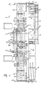
- the implement comprises a support frame, extending transversely to the intended direction of travel A, comprising one single frame beam 1, extending at least substantially transversely to the intended direction of travel of the machine and situated at least substantially in a horizontal plane.
- support beams 2 of U-profile-like formation and extending to the intended direction of travel A of the implement, are fitted on both sides of the support frame on the upper part of the frame beam 1.
- the support beams 2 are connected at the front with the lowermost part of upwardly extending supports 3 of a rectangular trestle 4.
- the upwardly extending supports 3 are interconnected on the uppermost part by means of a connection beam 5, extending transversely to the intended direction of travel A and situated at least substantially in a horizontal plane.
- connection beam 5 is connected with the uppermost part of the frame beam 1 by means of diverging supports 7, extending downwardly and rearwardly in an oblique plane.
- the trestle 4 comprises a three-point hitch for linkage to the three-point lifting device of a tractor.
- Two fixation points, constituted by plates 8 are provided at the level of the support beams 2 at the front of the supports 3, while a third fixation point, constituted by plates 9 is provided near the middle of the connection beam 5 at its front.
- the extremities of the frame beam 1 are fitted with supports 10, extending obliquely downwardly and rearwardly. Similar supports 10 are fixed spaced apart, on both sides of the middle of the frame beam 1. Between the lower extremities of the respective supports 10, a freely rotatable roller 12, respectively 13 is comprised by means of shafts 11 and bearings.
- the rollers, thus mounted to the frame beam 1, may be of a design as shown for the roller 12, right hand when viewed in intended direction of travel, i.e. in the version of a packer roller. However, the rollers may also be of a design as shown by means of the left hand roller 13, i.e. a roller comprising on its circumference longitudinal elements, being of rod-like formation and extending helically.
- the packer roller 12 comprises a cylindrical support 14, on which crenelated tines 15 are provided in an arrangement with equal spacings. Between the supports 10, a support 17 is fitted, by means of clamp brackets, to the frame beam 1 by means of arms 16, which support, when seen in plan view, is situated behind the axis of rotation of the roller 12. To the support 17, arms 18, extending downwardly, for scrapers 19 are fixed. The scrapers 19 comprise a scraping plate section 20, fitted to the lowermost part of the arms 18.
- Each plate section 20 extends to the proximity of the crenelated tines 15, whereby the sides directed towards the crenelated tines 15 will extend initially at least substantially parallel, as seen from the rear to the front, to incline subsequently into converging sides, all this in such a way that a V-shaped section will arise, directed obliquely forwardly and downwardly, leaning against the periphery of the cylindrical support 14 in a point where a radian embraces an angle of ⁇ 45° with the vertical, respectively horizontal plane via the axis of rotation of the roller (Fig. 3).
- the frame beam 1 forms part of a support frame, connected with the rectangular trestle 4 by means of the support beams 2, extending in the intended direction of travel A, whereby the support frame is supported during machine operation by means of supporting members afforded by the rollers 12, respectively 13, which occupy a fixed position with respect to the support frame.
- the support frame supported during machine operation by means of the rollers 12, respectively 13 and trestle 4, provides a support to a box-like frame beam 21, fitted to the support beams 2, beam 21 comprising soil working members 23, rotating about preferably vertical shafts 22, directed upwardly, these soil working members being arranged at an equal mutual spacing of, preferably about 25 cms.
- Each of the soil working members 23 comprises a support 23A, at least substantially horizontal, its extremities being fitted with soil working elements 23B, being of tine-like formation and extending downwardly.
- bearing housings 24 are provided at a mutual spacing on the sides of the support beams 2, turned away from one another, these housings supporting a shaft 25, extending into the intended direction of travel A and situated at least substantially parallel to a support beam 2.
- the shaft 25 comprises pivotable arms 26, leaning against the front side, respectively the rear side of the bearing housings and extending laterally, with a cross connection linking the pivotable arms (Fig. 3).
- the extremities of the arms 26, turned away from a support beam 2, brought closer to one another through a flexion (Fig. 1) are interconnected by means of a shaft 28, extending at least substantially parallel to the shaft 25.
- a shackle 29 can pivot freely about the extremities of the shaft 28, these extremities protruding from the arms 26.
- Each shackle 29 is fixed, freely pivotably, at its other end by means of a pin 30 to a support 31 near the front side, respectively the rear side of the box-like frame portion 21.
- Each of the top corners of the rectangular trestle 4 (Fig. 2) comprises a shaft 32, extending to the intended direction of travel A.
- a bushing of a tumbler 33 is pivotable, each of these tumblers comprising two pairs of arms, spaced apart.
- an extremity of a rod 35 is pivotably fixed by means of pin 34 with a tubular component 36 being fixed, by means of screw-thread, onto this rod, making possible the adjustment of this component with respect to the rod.
- the tubular component 36 is provided with a rod 37, which can be shifted within the tubular component and which can be fixed with respect to the tubular component by means of a pin 38, which allows conducting through corresponding orifices.
- the other extremity of the rod 37 is pivotably fitted by means of a pin 39, provided at the front side of the foremost pivotable arm 26.
- a screw spindle 41 is provided by means of a pivotable bushing-shaped component 40 with screw-thread, this screw spindle extending transversely to the intended direction of travel A and at least substantially parallel to the topmost side of the rectangular trestle 4.
- Each of the supports 10 is provided, at the rear side, with a bushing 43 in which a shaft 44, projecting into an upright, preferably vertical direction, is supported, with bushings 45 being pivotable about this shaft (Fig. 3).
- the bushings 45 are assembled to the inner side of a plate 46, extending at least substantially parallel to a vertical plane in the intended direction of travel A of the machine and occupying, during machine operation, a position as shown in the Figures 1 and 3.
- the plate 46 is fitted, near the middle on the inner side, with a coil spring 47, which has its other end hooked into an aperture in a lip 48 situated at the rear side of the frame beam 1 (Fig. 3 and 5). The plate 46 is pulled against the support 10 by means of the spring.
- the plate 46 is mainly rectangular, with the lowermost part of the substantially vertical front extending obliquely, partly downwardly and rearwardly. At the rear, the plate initially extends obliquely, from the horizontal lowermost part, rearwardly and upwardly, then inclining into the virtually vertical rear side, comprising the bushings 45. It will be seen in Fig. 3 that the plate 46 extends from before the frame portion 21 to behind the axis of rotation of the rollers 12, respectively 13, with the coil spring gripping the plate at least substantially near the centre between the back side of the frame port ion 21 and the front of the rollers 12, respectively 13.
- a protection 49 being of an angle iron-like formation is provided at the level of the supports 23A of the soil working members 23, with the aid of which protection stones or other hard objects, present in the soil during machine operation, can be stopped and conducted downwardly in the soil that has been loosened by the soil working members.
- the protection 49 being spring-loaded, it can pivot forwardly, all this in such a manner that hard objects, possibly getting between the supports 23A of the soil working members 23 and the back side of the protection, can be dismissed.
- each of the shafts 22 of a soil working member 23 is provided with a gear 50 with straight toothing, all this in such a manner that the gears on the shafts of adjacent soil working members 23 are in a mutually driving relation.
- the shaft of a soil working member 23 is extended upwardly, this extension reaching into a gear box 51, provided on the topmost part of the box-like frame section 21.
- the extension is engaged, through a conical gear transmission and a speed variation system 52, situated at the rear side of the gear box 51, with a shaft 53, extending to the intended direction of travel and protruding from the gear box at the front.
- the end of the shaft 53, protruding from the gear box can be coupled to the tractor PTO-shaft through an intermediate shaft 54.
- coupling means are shown for combining the machine according to Figures 1 - 4, with another implement, e.g. the shown seed drill 65. These coupling means are not shown in the Figures 1 - 3.
- the coupling means comprise two mutually interspaced guide members 55, each constituted by a U-profile, being fixed near the ends of the connecting beam 5 of the trestle 4, by means of support plates 56. It will be seen in Figure 5 that a guide member 55 projects, at the front, over the topmost linkage point of the three-point attachment, constituted by the plates 9 and, at the rear beyond the axis of rotation of the support rollers 12, respectively 13.
- the guide members 55 situated at least substantially over the support beams 2, extend parallel in respect of one another and are fixed on the frame beam 1 at the rear by means of supports 57. Both guide members 57 are installed in such a manner that the limbs of the U-profile are directed towards each other.
- the upper limb of each U-profile constitutes a guide member for rollers 58, situated on the uppermost and lowermost side and fitted in a freely rotatable manner to a plate-shaped support 59, directed upwards.
- Each plate-shaped support 59 has at least substantially the shape of a rectangular triangle, with the shortest base and perpendicular situated on the lowermost side and the longest base and perpendicular situated at the front.
- each triangular support 59 is provided with a roller 60.
- the roller 60 is installed on the shaft of a not shown hydraulic motor and has a toothing on its circumference, which toothing can intermesh with another one, provided on the inner side of the lowermost limb of the U-profile, constituting a guide member 55.
- the hypothenuse of the triangular support 59 is fitted with a pivot pin 61, about which arms 62, extending to the rear, are freely pivotable.
- the rear ends of the arms 62 are freely pivotable, being mounted by means of pins 63 to the upwardly directed sides of a rectangular trestle 64.
- the trestle 64 has a three-point attachment for coupling the three-point system of an implement to be combined with the machine, e.g. with the seed drill shown in this embodiment, which seed drill may have a known design.
- each of the soil working members 23 can be made to rotate from the tractor PTO-shaft through the intermediate shaft 54 and the transmission, as described before.
- adjacently situated soil working members rotate in mutually opposite directions, as shown by the arrows in Figure 1, with the soil working elements 23B extending downwardly and being of tine-like formation, working at least adjacent strips of soil.
- the box-like frame portion 1, supporting the soil working members 23, is held by a support construction, situated behind the frame portion and comprising the single frame beam 1, supported by means of the adjacent rollers 12, respectively 13, occupying a fixed position with respect to the frame beam.
- the support frame is provided with coupling means, situated in front of the frame portion, these means being connected with the frame beam 1 through the support beams 2, extending in the intended direction of travel, and these means comprising the trestle 4, which is linked with the three-point lifting device of the tractor during machine operation.
- the box-like frame portion 21 with the soil working members 23, supported by it is allowed to move freely, in height and vertically, to a certain extent, through the pivotal connection, embracing the shackles 29 and the pivotable arms 26, and having at least two pivotable shafts, extending in the intended direction of travel A.
- a rod 37 shifts upwardly with respect to the tubular component 36.
- the assembly may move farther, with pin 38 fitted, about the pivotable axes 32 before the tumblers 33, so that, beside an individual, vertical height movement by means of every pivotable connection, comprising the pivotable arms 26 and the shackles 29, a total oscillatory movement is possible for the box-like frame portion 1, supporting the soil working members 23.
- each plate 46 can deflect about the pivotable shaft 44, against the action of spring 47, this axis being situated at the rear side and extending at least substantially in a vertical plane, making possible an adaption to the structure of the soil and the quantity to be worked. Moreover, the plate can deflect sideways when hitting hard objects, after which the plate will be immediately restored to its original position against the action of the spring 47.
- the plate 46 occupying a fixed position with respect to the supporting rollers 12, respectively 13, the lowermost side of the plate will invariably be in the position as shown in Figure 3.
- packer rollers 12 it can be achieved by means of the scrapers 19, fitted collectively to the tubular holder 17, that soil, possibly lodging between the crenelated tines 15, is scraped off.
- the soil is caught from the middle by the point of the V-shaped part of the scraping plate section 20, to be subsequently loosened gradually into the direction of the respective tine crenelations and - as is evident from Figure 3 - to be smoothed out close over the soil surface, all this in such a manner that virtually no clods are left behind on the tilled strip of land.
- the assembly allows a combination with another implement, e.g. the seed drill 65, shown in working position.
- the supports 59 can be moved upwardly, through excitation by a (not shown) hydraulic motor, with the aid of the roller 61 via the guide members 55, till the point when the assembly assumes a position as shown in the Figure by means of dashed lines.
- a downward movement of the arms 62, constituting a parallelogram, is avoided by the buffers 66, provided at the back of the supports 59.
- the supports 59 can be made to move back, along the guide members 55, into the position for operation, assisted by the seed drill's own weight.
- a winch installation which may be mounted on the topmost side of the rectangular trestle 4, possibly to be actuated from the tractor.
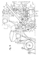
- the machine is provided with a crumbling member 67, situated between the row of soil working members 23 and the rotating support members, constituted by the rollers 12, respectively 13.
- the crumbling member 67 is constituted by a plate, comprising a straight section that extends at least substantially parallel to a vertical direction and a straight section that extends downwardly and rearwardly, in an oblique plane, all this in such a manner that the transition of both sections is situated near the middle of the plate.
- the plate At a distance from the middle, the plate comprises on both sides a shackle 68, pivotably assembled (Figure 7).
- the pivotable shaft extending in the intended direction of travel A, is constituted by a bolt 69, about which a compression spring 70 is provided, all this in such a way that the plate, with respect to the shackle, can pivot to the rear about an imaginary axis, extending transversely to the intended direction of travel A.
- Each shackle 68 has a pivotal connection, by means of an axle 71, extending to the intended direction of travel, with one extremity of a pivot arm 72, extending in an oblique plane upwardly and towards the middle of the frame beam 1 ( Figure 7), the other extremity being fitted pivotably, by means of a shaft 73 situated parallel to the shaft 71, between two supports 74 and 75, mounted to the support beams 2 and to the front side, respectively the rear side of the frame beam 1.
- each arm 72 is provided with a chain 76, which may work in conjunction with a hook 77, provided on the rear side of the frame beam 1.
- crumbling member 67 By means of the depicted crumbling member 67 the soil, moved to the rear by the soil working members 23, can be caught, as a consequence of which this soil will remain longer within reach of the soil working members and the crumbling can be intensified, after which this soil can flow away in a layer of uniform thickness via the lowermost part of the member into the direction of the support rollers 12, respectively 13.
- the member When meeting hard objects, the member is allowed to deflect backwardly about the imaginary cross axis mentioned before, against the action of the spring 76, fitted about the bolts 69.
- a compact construction makes it possible to obtain a suspension for the crumbling member of such a nature, that this member is enabled to move in a vertical direction during operation and, thus, to maintain its working position.
- the chains 76 By means of the chains 76, the required height of the crumbling member 67 can be adjusted, while at the same time the beam is kept from moving downwardly too far during transport. It is also possible, by means of the chains 76, to bring the crumbling member 67 into a position, in which it is out of operation.
- This embodiment also embraces the possibility to combine the machine with another implement.
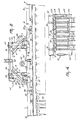
- the seed drill 65 as shown in Figure 5 is referred to.
- the support beams 2A are of U-profile-like formation, constituting guide members that are so arranged that the limbs of the U-profiles are directed towards one another.
- the rollers 78 and 79 provided within the limbs of each U-profile, support a substantially triangular plate 80, extending to an upward direction.
- the plates are interconnected by means of a beam 81 ( Figure 7).
- a transfer of the plates 80 with respect to the guide members 2A can be effected by means of the rollers 78.
- the rollers 78 are arranged on the shaft of a hydraulic motor 82 and equipped with a toothing that can intermesh with a toothing on a limb of the guide member 2A.
- each of the plates 80 is provided with pivotable arms 83, arranged by means of axles 82A, which constitute sides of a parallelogram and have a greater length than the arms 62 pertaining to the first embodiment.
- the arms 83 are pivotably connected with a trestle provided with a three-point attachment for linkage to the seed drill 65.
- a hydraulic ram 84 is arranged between the hindmost pivot point of each topmost arm 83 and the foremost pivot point of each lowermost arm 83, all this in such a manner that, for bringing the assembly into a transport position, the seed drill 65 can be lifted by means of the hydraulic rams and the arms, before the assembly is transposable at least substantially parallel to the intended direction of travel A by means of the supports 80, movable with respect to the guide members 2A, till the point when the assembly has assumed a position as shown by the dashed lines in Figure 6.
- a reversed adjustment can be carried out.
- other means of adjustment e.g. a winch, can be applied.
- the support frame described before comprising a single frame beam, situated behind the soil working members, this beam being connected with a linkage trestle via support beams 2, respectively 2A, extending forwardly over the row of soil working members, this beam moreover being supported by means of at least one support member 12, respectively 13, a simple and yet strong construction is obtained for the fixation of a frame portion 21, holding the soil working members 23.
- the assembly is allowed to be compact in that the frame portion, holding the soil working members, is transposable in a vertical direction with respect to the support frame, enabled to do so by the specific pivotal connection.
- the pivotal connection also comprises means for the working depth adjustment of the soil working members.
Landscapes
- Life Sciences & Earth Sciences (AREA)
- Engineering & Computer Science (AREA)
- Mechanical Engineering (AREA)
- Soil Sciences (AREA)
- Environmental Sciences (AREA)
- Soil Working Implements (AREA)
- Agricultural Machines (AREA)
Priority Applications (1)
| Application Number | Priority Date | Filing Date | Title |
|---|---|---|---|
| EP89121618A EP0361545A3 (fr) | 1985-01-24 | 1986-01-22 | Machines pour travailler le sol |
Applications Claiming Priority (3)
| Application Number | Priority Date | Filing Date | Title |
|---|---|---|---|
| NL8500187 | 1985-01-24 | ||
| NL8500187A NL8500187A (nl) | 1985-01-24 | 1985-01-24 | Grondbewerkingsmachine. |
| EP89121618A EP0361545A3 (fr) | 1985-01-24 | 1986-01-22 | Machines pour travailler le sol |
Related Parent Applications (2)
| Application Number | Title | Priority Date | Filing Date |
|---|---|---|---|
| EP86200100.5 Division | 1986-01-22 | ||
| EP86200100A Division EP0189235B1 (fr) | 1985-01-24 | 1986-01-22 | Machine pour cultiver le sol |
Publications (2)
| Publication Number | Publication Date |
|---|---|
| EP0361545A2 true EP0361545A2 (fr) | 1990-04-04 |
| EP0361545A3 EP0361545A3 (fr) | 1990-04-25 |
Family
ID=19845416
Family Applications (3)
| Application Number | Title | Priority Date | Filing Date |
|---|---|---|---|
| EP86200100A Expired - Lifetime EP0189235B1 (fr) | 1985-01-24 | 1986-01-22 | Machine pour cultiver le sol |
| EP19880202450 Expired EP0311221B1 (fr) | 1985-01-24 | 1986-01-22 | Machines pour travailler le sol |
| EP89121618A Withdrawn EP0361545A3 (fr) | 1985-01-24 | 1986-01-22 | Machines pour travailler le sol |
Family Applications Before (2)
| Application Number | Title | Priority Date | Filing Date |
|---|---|---|---|
| EP86200100A Expired - Lifetime EP0189235B1 (fr) | 1985-01-24 | 1986-01-22 | Machine pour cultiver le sol |
| EP19880202450 Expired EP0311221B1 (fr) | 1985-01-24 | 1986-01-22 | Machines pour travailler le sol |
Country Status (3)
| Country | Link |
|---|---|
| EP (3) | EP0189235B1 (fr) |
| DE (2) | DE3686333T2 (fr) |
| NL (1) | NL8500187A (fr) |
Families Citing this family (7)
| Publication number | Priority date | Publication date | Assignee | Title |
|---|---|---|---|---|
| DD288961A5 (de) * | 1989-11-08 | 1991-04-18 | Komb. Forschritt Landmaschinen Veb Bodenbearbeitungsgeraete "Karl Marx",De | Geraete-kombination zur bodenbearbeitung und aussaat |
| FR2732857B1 (fr) * | 1995-04-13 | 1997-06-20 | Kuhn Sa | Dispositif de recouvrement des graines implantees dans le sol destine a equiper un semoir agricole |
| GB2305837B (en) * | 1995-10-05 | 1999-10-06 | Leslie Brown | Seeding drill |
| DE19816813A1 (de) * | 1998-04-16 | 1999-10-21 | Lemken Gmbh & Co Kg | Landwirtschaftliche Bestellkombination |
| DE202013010042U1 (de) * | 2013-10-31 | 2015-02-02 | Alois Pöttinger Maschinenfabrik Ges.m.b.H. | Bodenbearbeitungsmaschine |
| FR3012721B1 (fr) * | 2013-11-05 | 2016-12-30 | Alois Pottinger Maschf Gmbh | Machine de travail du sol |
| CN105960866B (zh) * | 2016-06-22 | 2019-04-30 | 河南省农业科学院粮食作物研究所 | 一种玉米贴茬深松旋耕机 |
Citations (1)
| Publication number | Priority date | Publication date | Assignee | Title |
|---|---|---|---|---|
| FR2416634A1 (fr) * | 1978-02-13 | 1979-09-07 | Crete Guerin | Dispositif de garde laterale pour appareil preparateur de sol |
Family Cites Families (6)
| Publication number | Priority date | Publication date | Assignee | Title |
|---|---|---|---|---|
| DE1632779A1 (de) * | 1968-02-03 | 1971-01-07 | Cramer & Soehne Maschf | Bodenbearbeitungsgeraet fuer Arbeitskombinationen |
| US4147117A (en) * | 1969-06-10 | 1979-04-03 | C. Van Der Lely N.V. | Cultivating implements |
| NL167575C (nl) * | 1972-03-08 | 1982-01-18 | Lely Nv C Van Der | Grondbewerkingsmachine. |
| NL181702C (nl) * | 1975-06-05 | 1987-10-16 | Lely Nv C Van Der | Grondbewerkingsmachine. |
| NL8204382A (nl) * | 1982-09-29 | 1984-04-16 | Lely Nv C Van Der | Grondbewerkingsmachine. |
| NL191167B (nl) * | 1982-12-06 | 1994-10-03 | Lely Nv C Van Der | Samenstel van een rol en een zaaimachine. |
-
1985
- 1985-01-24 NL NL8500187A patent/NL8500187A/nl not_active Application Discontinuation
-
1986
- 1986-01-22 DE DE19863686333 patent/DE3686333T2/de not_active Expired - Fee Related
- 1986-01-22 EP EP86200100A patent/EP0189235B1/fr not_active Expired - Lifetime
- 1986-01-22 EP EP19880202450 patent/EP0311221B1/fr not_active Expired
- 1986-01-22 EP EP89121618A patent/EP0361545A3/fr not_active Withdrawn
- 1986-01-22 DE DE8686200100T patent/DE3677789D1/de not_active Expired - Fee Related
Patent Citations (1)
| Publication number | Priority date | Publication date | Assignee | Title |
|---|---|---|---|---|
| FR2416634A1 (fr) * | 1978-02-13 | 1979-09-07 | Crete Guerin | Dispositif de garde laterale pour appareil preparateur de sol |
Also Published As
| Publication number | Publication date |
|---|---|
| EP0311221A1 (fr) | 1989-04-12 |
| DE3677789D1 (de) | 1991-04-11 |
| DE3686333D1 (de) | 1992-09-10 |
| EP0189235A2 (fr) | 1986-07-30 |
| DE3686333T2 (de) | 1993-03-18 |
| EP0361545A3 (fr) | 1990-04-25 |
| NL8500187A (nl) | 1986-08-18 |
| EP0189235B1 (fr) | 1991-03-06 |
| EP0189235A3 (en) | 1987-04-29 |
| EP0311221B1 (fr) | 1992-08-05 |
Similar Documents
| Publication | Publication Date | Title |
|---|---|---|
| US3983943A (en) | Soil cultivating implement combinations | |
| US4585075A (en) | Soil leveling apparatus with improved frame and hitch | |
| EP0123561A1 (fr) | Herse à dent flexible pour la préparation de lit de semence | |
| EP0311221B1 (fr) | Machines pour travailler le sol | |
| US4114695A (en) | Rotary harrow with pivotable coupling assembly | |
| EP0475480B1 (fr) | Machine à travail du sol | |
| US3608646A (en) | Rotary hoe | |
| EP0059520B1 (fr) | Machine pour le travail du sol | |
| EP0436975A1 (fr) | Machine pour le travail du sol | |
| US4884640A (en) | Soil cultivating implements | |
| GB2153642A (en) | Soil cultivating implements | |
| EP0262734B1 (fr) | Machine pour le travail du sol | |
| US4099575A (en) | Soil cultivating implements | |
| EP0264987A1 (fr) | Machine pour cultiver la terre | |
| GB2132864A (en) | Soil cultivating implements | |
| EP0666015B1 (fr) | Machine agricole | |
| US4149600A (en) | Soil cultivating machines | |
| EP0289094B1 (fr) | Machine à cultiver le sol | |
| US2918979A (en) | Rooting and raking apparatus | |
| EP0200273A1 (fr) | Machine pour le travail du sol | |
| EP0166493A2 (fr) | Machines pour le travail du sol | |
| US2761366A (en) | Cotton chopper | |
| CA1326355C (fr) | Niveleuse a chassis et attelage ameliores | |
| EP0160348A2 (fr) | Machine agricole pour la préparation du sol | |
| EP0305600A1 (fr) | Appareil préparateur de sol |
Legal Events
| Date | Code | Title | Description |
|---|---|---|---|
| PUAI | Public reference made under article 153(3) epc to a published international application that has entered the european phase |
Free format text: ORIGINAL CODE: 0009012 |
|
| PUAL | Search report despatched |
Free format text: ORIGINAL CODE: 0009013 |
|
| AC | Divisional application: reference to earlier application |
Ref document number: 189235 Country of ref document: EP |
|
| AK | Designated contracting states |
Kind code of ref document: A2 Designated state(s): DE FR GB NL |
|
| AK | Designated contracting states |
Kind code of ref document: A3 Designated state(s): DE FR GB NL |
|
| 17P | Request for examination filed |
Effective date: 19901023 |
|
| 17Q | First examination report despatched |
Effective date: 19911023 |
|
| STAA | Information on the status of an ep patent application or granted ep patent |
Free format text: STATUS: THE APPLICATION IS DEEMED TO BE WITHDRAWN |
|
| 18D | Application deemed to be withdrawn |
Effective date: 19920303 |