EP0361487A1 - Membransystem - Google Patents
Membransystem Download PDFInfo
- Publication number
- EP0361487A1 EP0361487A1 EP19890118011 EP89118011A EP0361487A1 EP 0361487 A1 EP0361487 A1 EP 0361487A1 EP 19890118011 EP19890118011 EP 19890118011 EP 89118011 A EP89118011 A EP 89118011A EP 0361487 A1 EP0361487 A1 EP 0361487A1
- Authority
- EP
- European Patent Office
- Prior art keywords
- membrane
- axis
- membrane system
- wall thickness
- diaphragm
- Prior art date
- Legal status (The legal status is an assumption and is not a legal conclusion. Google has not performed a legal analysis and makes no representation as to the accuracy of the status listed.)
- Withdrawn
Links
- 239000012528 membrane Substances 0.000 claims description 101
- 239000000463 material Substances 0.000 claims description 7
- 238000004519 manufacturing process Methods 0.000 claims 1
- 230000003247 decreasing effect Effects 0.000 abstract description 2
- 208000013201 Stress fracture Diseases 0.000 description 2
- 239000011324 bead Substances 0.000 description 2
- 230000007423 decrease Effects 0.000 description 2
- 238000005452 bending Methods 0.000 description 1
- 230000033228 biological regulation Effects 0.000 description 1
- 230000001419 dependent effect Effects 0.000 description 1
- 238000011161 development Methods 0.000 description 1
- 230000018109 developmental process Effects 0.000 description 1
- 239000000428 dust Substances 0.000 description 1
- 239000003292 glue Substances 0.000 description 1
- 239000007787 solid Substances 0.000 description 1
- 239000013589 supplement Substances 0.000 description 1
Images
Classifications
-
- H—ELECTRICITY
- H04—ELECTRIC COMMUNICATION TECHNIQUE
- H04R—LOUDSPEAKERS, MICROPHONES, GRAMOPHONE PICK-UPS OR LIKE ACOUSTIC ELECTROMECHANICAL TRANSDUCERS; DEAF-AID SETS; PUBLIC ADDRESS SYSTEMS
- H04R7/00—Diaphragms for electromechanical transducers; Cones
- H04R7/02—Diaphragms for electromechanical transducers; Cones characterised by the construction
- H04R7/12—Non-planar diaphragms or cones
- H04R7/122—Non-planar diaphragms or cones comprising a plurality of sections or layers
-
- H—ELECTRICITY
- H04—ELECTRIC COMMUNICATION TECHNIQUE
- H04R—LOUDSPEAKERS, MICROPHONES, GRAMOPHONE PICK-UPS OR LIKE ACOUSTIC ELECTROMECHANICAL TRANSDUCERS; DEAF-AID SETS; PUBLIC ADDRESS SYSTEMS
- H04R7/00—Diaphragms for electromechanical transducers; Cones
- H04R7/02—Diaphragms for electromechanical transducers; Cones characterised by the construction
- H04R7/12—Non-planar diaphragms or cones
- H04R7/127—Non-planar diaphragms or cones dome-shaped
Definitions
- the invention relates to a membrane system according to the preamble of claim 1.
- a membrane system is known from US Pat. No. 4,532,383.
- the invention is applicable to a membrane or a membrane part of membrane systems for sound transducers, in particular loudspeakers of all kinds, e.g. for dome emitters, for pressure chamber systems, for a middle part of a loudspeaker cone or plate.
- loudspeakers of all kinds e.g. for dome emitters, for pressure chamber systems, for a middle part of a loudspeaker cone or plate.
- undesired partial vibrations lead to distortions in the radiated sound vibrations.
- the object of the invention is to provide a membrane system in which the distortions of radiated sound vibrations are low compared to the vibrations of its drive.
- the invention is based on calculations and tests which have shown that with the design specification found, good mechanical properties of a membrane can be achieved with the result that disruptive partial vibrations are largely avoided. About such partial vibrations To contain, a certain course of the bending stiffness and the area moment of inertia must be maintained or approximated from the inside to the outside of the membrane.
- stiffening struts or trusses are preferably dispensed with and instead a preferably solid shape is selected, to which foamed variants are also to be counted.
- an edge ring can also be provided, which has the membrane at its edge and which is in turn clamped in place so that a guidance of the membrane in the axial direction is ensured.
- the fastening zone can also be the zone where the membrane is connected to a cone membrane of a loudspeaker, the membrane covering or bridging over the inner edge or the center of the cone membrane.
- the fastening zone where the membrane is connected to the cone membrane and the drive can be at the same radial coordinate value.
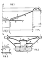
- FIG. 1 shows a half of a radial section through a cone membrane M, which is provided on its inner edge with a radial guide R f (not mandatory) and an electromagnetic drive E, which acts in the direction of the membrane axis 1.
- the cone membrane is rigid, ring-shaped, rotationally symmetrical and conical.
- the drive is diaphragm and cone diaphragm drive at the same time.
- the edge ring Rr has an annular extension F on its outer edge, which serves to clamp the edge ring and thus indirectly also the membrane M.
- a rotationally symmetrical, rigid membrane P which serves as a dome oscillator and as dust protection for the drive E.
- the cone membrane M and the membrane P are glued together in a manner not shown.
- the glue point is called the fastening zone.
- Your radial Expansion has been assumed to be negligibly small in the schematic FIG. 1.
- the membrane P and the cone membrane M can also be made in one piece.
- the membrane P driven by the drive E in the form of a voice coil, acts as a piston oscillator.
- Their wall thickness h increases in a central ring area around R0 / 2 with decreasing values of the radial coordinate r.
- the amount of the constant c and thus the mean value of the wall thickness of the membrane is determined in a known manner either on the basis of empirical values with safety supplements or on the basis of calculations or tests.
- the strength of the selected material and its density (specific weight) must be taken into account, because the lower limit frequency of a sound transducer depends on the moving masses.
- the wall thickness must therefore be chosen in accordance with previous practice so that at the maximum deflection (which is dependent on the predetermined maximum load capacity of the sound transducer) the membrane does not experience fatigue fractures or inadmissible clinking.
- the membrane preferably consists of homogeneous or foamed material with a smooth surface; if a higher effort and thus a higher price is permitted, sandwich molds are preferred.
- the loudspeaker shown schematically in section in FIG. 2 has a permanent magnetic ring magnet 2 with a soft magnetic core 3 and with a pole plate 4.
- a diaphragm drive E 'on a hollow cylinder Z which is guided by a radial guide Rf and via which a cone membrane M is driven.
- This is a so-called Nawi membrane (membrane that cannot be unwound) which deviates from the cone shape (FIG. 1), but nevertheless has a wall thickness profile corresponding to FIG. 1.
- the cone membrane shape resembles an exponential funnel.
- the radial coordinate for the membrane drive E 'does not coincide with the radial coordinate for the edge of the membrane P. However, if one only looks at the membrane P, it is actually directly driven at its edge by the cone membrane M, so the cone membrane is the "drive" for the membrane.
- the cone membrane M merges at its outer edge into an edge ring R r , the extension F of which is attached to a loudspeaker basket 5, which in turn is connected to the pole plate 4.
- the statements made in connection with FIG. 1 apply to the edge ring.
- FIG 3 shows a cross section of another membrane P ', but the course of the wall thickness h is again the same as in Figure 1.
- the membrane is loaded with a weight, consisting of a rod-shaped connecting member G and a body K attached to it, which in turn is connected to a centering membrane Z, which is mounted at the edge in a fixed bearing L.
Landscapes
- Engineering & Computer Science (AREA)
- Multimedia (AREA)
- Physics & Mathematics (AREA)
- Acoustics & Sound (AREA)
- Signal Processing (AREA)
- Diaphragms For Electromechanical Transducers (AREA)
- Audible-Bandwidth Dynamoelectric Transducers Other Than Pickups (AREA)
Applications Claiming Priority (4)
| Application Number | Priority Date | Filing Date | Title |
|---|---|---|---|
| DE3833238 | 1988-09-30 | ||
| DE3833238 | 1988-09-30 | ||
| DE3838853 | 1988-11-17 | ||
| DE19883838853 DE3838853C1 (enExample) | 1988-09-30 | 1988-11-17 |
Publications (1)
| Publication Number | Publication Date |
|---|---|
| EP0361487A1 true EP0361487A1 (de) | 1990-04-04 |
Family
ID=25872731
Family Applications (2)
| Application Number | Title | Priority Date | Filing Date |
|---|---|---|---|
| EP19890911046 Pending EP0436615A1 (de) | 1988-09-30 | 1989-09-28 | Membransystem |
| EP19890118011 Withdrawn EP0361487A1 (de) | 1988-09-30 | 1989-09-28 | Membransystem |
Family Applications Before (1)
| Application Number | Title | Priority Date | Filing Date |
|---|---|---|---|
| EP19890911046 Pending EP0436615A1 (de) | 1988-09-30 | 1989-09-28 | Membransystem |
Country Status (4)
| Country | Link |
|---|---|
| EP (2) | EP0436615A1 (enExample) |
| JP (1) | JPH04503739A (enExample) |
| DE (1) | DE3838853C1 (enExample) |
| WO (1) | WO1990003709A1 (enExample) |
Families Citing this family (4)
| Publication number | Priority date | Publication date | Assignee | Title |
|---|---|---|---|---|
| EP0529143A3 (en) * | 1991-08-30 | 1993-07-07 | Filip Keller | Diaphragm for loudspeaker or microphone |
| FR2706944A1 (en) * | 1993-06-24 | 1994-12-30 | Delplanque Jean Claude | Compact turbomachine stator with alternating curvature of the (moving) blades |
| US7945069B2 (en) | 2004-11-22 | 2011-05-17 | Harman International Industries, Incorporated | Loudspeaker plastic cone body |
| JP7025833B2 (ja) * | 2019-09-17 | 2022-02-25 | 株式会社サウンドファン | スピーカユニット、及びスピーカ |
Citations (3)
| Publication number | Priority date | Publication date | Assignee | Title |
|---|---|---|---|---|
| DE1088099B (de) * | 1957-02-23 | 1960-09-01 | Isophon Werke Ges Mit Beschrae | Druckkammersystem fuer elektrodynamische Lautsprecher |
| US3862376A (en) * | 1973-01-19 | 1975-01-21 | Stanley F White | Cone construction for loudspeaker |
| WO1988000423A1 (fr) * | 1986-07-04 | 1988-01-14 | Ant Nachrichtentechnik Gmbh | Systeme de membrane avec plaque rigide en flexion et symetrique en rotation, servant d'element de reflexion ou de reception du son |
Family Cites Families (1)
| Publication number | Priority date | Publication date | Assignee | Title |
|---|---|---|---|---|
| US4532383A (en) * | 1980-01-04 | 1985-07-30 | Willy Erazm A | Electroacoustic transducer having a variable thickness diaphragm |
-
1988
- 1988-11-17 DE DE19883838853 patent/DE3838853C1/de not_active Expired
-
1989
- 1989-09-28 WO PCT/EP1989/001142 patent/WO1990003709A1/de not_active Ceased
- 1989-09-28 EP EP19890911046 patent/EP0436615A1/de active Pending
- 1989-09-28 EP EP19890118011 patent/EP0361487A1/de not_active Withdrawn
- 1989-09-28 JP JP1510301A patent/JPH04503739A/ja active Pending
Patent Citations (3)
| Publication number | Priority date | Publication date | Assignee | Title |
|---|---|---|---|---|
| DE1088099B (de) * | 1957-02-23 | 1960-09-01 | Isophon Werke Ges Mit Beschrae | Druckkammersystem fuer elektrodynamische Lautsprecher |
| US3862376A (en) * | 1973-01-19 | 1975-01-21 | Stanley F White | Cone construction for loudspeaker |
| WO1988000423A1 (fr) * | 1986-07-04 | 1988-01-14 | Ant Nachrichtentechnik Gmbh | Systeme de membrane avec plaque rigide en flexion et symetrique en rotation, servant d'element de reflexion ou de reception du son |
Also Published As
| Publication number | Publication date |
|---|---|
| JPH04503739A (ja) | 1992-07-02 |
| EP0436615A1 (de) | 1991-07-17 |
| DE3838853C1 (enExample) | 1989-11-30 |
| WO1990003709A1 (de) | 1990-04-05 |
Similar Documents
| Publication | Publication Date | Title |
|---|---|---|
| DE69616989T2 (de) | Adapterring für audioschwingspule | |
| DE2924204C2 (enExample) | ||
| EP0480160B1 (de) | Kalotten-Hochton-Lautsprecher | |
| DE2946618C2 (enExample) | ||
| DE2933425C2 (enExample) | ||
| DE60009692T2 (de) | Elektromagnetischer wandler und tragbares kommunikationsgerät | |
| DE1207964B (de) | Mikrophonmembran | |
| DE2932942A1 (de) | Lautsprecher | |
| DE3507708C2 (enExample) | ||
| DE2401132A1 (de) | Schalltrichter zur akustischen impedanztransformation | |
| AT397898B (de) | Membran für elektrodynamische wandler | |
| DE69011502T2 (de) | Dynamisches Mikrophon und Verfahren zu seiner Herstellung. | |
| EP0271894A2 (de) | Hydraulisch dämpfendes Motorlager | |
| DE3838853C1 (enExample) | ||
| DE2949115B2 (de) | Dynamischer Wandler mit einer Schwingspule in einem mit einer magnetischen Flüssigkeit gefüllten Luftspalt zum Einfüllen und/oder gleichmäßigen Verteilen dieser Flüssigkeit | |
| EP0313560B1 (de) | Membransystem mit rotationssymmetrischer biegesteifer platte als schallabstrahlendes oder -aufnehmendes element | |
| EP0531691B1 (de) | Schwingspulsystem für einen elektromagnetischen Wandler | |
| DE69831855T2 (de) | Lautsprecher | |
| DE3721068C2 (enExample) | ||
| DE3227451A1 (de) | Piezoelektrischer wandler mit integrierter treiberstufe und fuehler | |
| DE3622558C2 (enExample) | ||
| DE3622526C2 (enExample) | ||
| EP0055841A1 (de) | Elektrodynamisches Lautsprechersystem mit kalottenförmiger Membran | |
| EP0508150A2 (de) | Lautsprecher mit Sicke und (Einbauab-)Dichtung vereinigendem Bauteil | |
| DE3831706A1 (de) | Membran fuer lautsprecher |
Legal Events
| Date | Code | Title | Description |
|---|---|---|---|
| PUAI | Public reference made under article 153(3) epc to a published international application that has entered the european phase |
Free format text: ORIGINAL CODE: 0009012 |
|
| AK | Designated contracting states |
Kind code of ref document: A1 Designated state(s): ES GR |
|
| 17P | Request for examination filed |
Effective date: 19900917 |
|
| RBV | Designated contracting states (corrected) |
Designated state(s): AT BE CH ES FR GB GR IT LI NL SE |
|
| XX | Miscellaneous |
Free format text: VERBUNDEN MIT 89911046.4/0436615 (EUROPAEISCHE ANMELDENUMMER/VEROEFFENTLICHUNGSNUMMER) DURCH ENTSCHEIDUNG VOM 12.08.91. |
|
| RAP1 | Party data changed (applicant data changed or rights of an application transferred) |
Owner name: KRUEGER, HELMUT |
|
| 17Q | First examination report despatched |
Effective date: 19920214 |
|
| STAA | Information on the status of an ep patent application or granted ep patent |
Free format text: STATUS: THE APPLICATION IS DEEMED TO BE WITHDRAWN |
|
| 18D | Application deemed to be withdrawn |
Effective date: 19930926 |