EP0360833B1 - Symmetrische optische vorrichtung - Google Patents
Symmetrische optische vorrichtung Download PDFInfo
- Publication number
- EP0360833B1 EP0360833B1 EP88905471A EP88905471A EP0360833B1 EP 0360833 B1 EP0360833 B1 EP 0360833B1 EP 88905471 A EP88905471 A EP 88905471A EP 88905471 A EP88905471 A EP 88905471A EP 0360833 B1 EP0360833 B1 EP 0360833B1
- Authority
- EP
- European Patent Office
- Prior art keywords
- quantum well
- optical
- light beam
- state
- light beams
- Prior art date
- Legal status (The legal status is an assumption and is not a legal conclusion. Google has not performed a legal analysis and makes no representation as to the accuracy of the status listed.)
- Expired - Lifetime
Links
- 230000003287 optical effect Effects 0.000 title claims abstract description 136
- 238000010521 absorption reaction Methods 0.000 claims abstract description 53
- 239000004065 semiconductor Substances 0.000 claims abstract description 10
- 230000005540 biological transmission Effects 0.000 abstract description 51
- 230000000295 complement effect Effects 0.000 abstract description 38
- 230000008859 change Effects 0.000 description 9
- 230000000694 effects Effects 0.000 description 9
- 239000000758 substrate Substances 0.000 description 8
- 230000009102 absorption Effects 0.000 description 7
- 230000002238 attenuated effect Effects 0.000 description 7
- 239000004020 conductor Substances 0.000 description 6
- 230000004044 response Effects 0.000 description 5
- 238000010586 diagram Methods 0.000 description 3
- 230000006870 function Effects 0.000 description 3
- 238000002955 isolation Methods 0.000 description 3
- 229910001218 Gallium arsenide Inorganic materials 0.000 description 2
- XUIMIQQOPSSXEZ-UHFFFAOYSA-N Silicon Chemical group [Si] XUIMIQQOPSSXEZ-UHFFFAOYSA-N 0.000 description 2
- 230000008901 benefit Effects 0.000 description 2
- 230000007423 decrease Effects 0.000 description 2
- 238000005530 etching Methods 0.000 description 2
- 239000000463 material Substances 0.000 description 2
- 238000000034 method Methods 0.000 description 2
- 238000001451 molecular beam epitaxy Methods 0.000 description 2
- 230000002829 reductive effect Effects 0.000 description 2
- 230000002441 reversible effect Effects 0.000 description 2
- XAGFODPZIPBFFR-UHFFFAOYSA-N aluminium Chemical compound [Al] XAGFODPZIPBFFR-UHFFFAOYSA-N 0.000 description 1
- 229910052782 aluminium Inorganic materials 0.000 description 1
- 230000003466 anti-cipated effect Effects 0.000 description 1
- 230000006399 behavior Effects 0.000 description 1
- ATBAMAFKBVZNFJ-UHFFFAOYSA-N beryllium atom Chemical group [Be] ATBAMAFKBVZNFJ-UHFFFAOYSA-N 0.000 description 1
- 238000003486 chemical etching Methods 0.000 description 1
- 150000001875 compounds Chemical class 0.000 description 1
- 230000003247 decreasing effect Effects 0.000 description 1
- 238000000151 deposition Methods 0.000 description 1
- 230000008021 deposition Effects 0.000 description 1
- 238000004519 manufacturing process Methods 0.000 description 1
- 230000004048 modification Effects 0.000 description 1
- 238000012986 modification Methods 0.000 description 1
- 230000010355 oscillation Effects 0.000 description 1
- 230000000717 retained effect Effects 0.000 description 1
- 229910052710 silicon Inorganic materials 0.000 description 1
- 239000010703 silicon Substances 0.000 description 1
Images


Classifications
-
- B—PERFORMING OPERATIONS; TRANSPORTING
- B82—NANOTECHNOLOGY
- B82Y—SPECIFIC USES OR APPLICATIONS OF NANOSTRUCTURES; MEASUREMENT OR ANALYSIS OF NANOSTRUCTURES; MANUFACTURE OR TREATMENT OF NANOSTRUCTURES
- B82Y20/00—Nanooptics, e.g. quantum optics or photonic crystals
-
- G—PHYSICS
- G02—OPTICS
- G02F—OPTICAL DEVICES OR ARRANGEMENTS FOR THE CONTROL OF LIGHT BY MODIFICATION OF THE OPTICAL PROPERTIES OF THE MEDIA OF THE ELEMENTS INVOLVED THEREIN; NON-LINEAR OPTICS; FREQUENCY-CHANGING OF LIGHT; OPTICAL LOGIC ELEMENTS; OPTICAL ANALOGUE/DIGITAL CONVERTERS
- G02F3/00—Optical logic elements; Optical bistable devices
- G02F3/02—Optical bistable devices
- G02F3/028—Optical bistable devices based on self electro-optic effect devices [SEED]
-
- G—PHYSICS
- G11—INFORMATION STORAGE
- G11C—STATIC STORES
- G11C7/00—Arrangements for writing information into, or reading information out from, a digital store
- G11C7/005—Arrangements for writing information into, or reading information out from, a digital store with combined beam-and individual cell access
-
- H—ELECTRICITY
- H10—SEMICONDUCTOR DEVICES; ELECTRIC SOLID-STATE DEVICES NOT OTHERWISE PROVIDED FOR
- H10F—INORGANIC SEMICONDUCTOR DEVICES SENSITIVE TO INFRARED RADIATION, LIGHT, ELECTROMAGNETIC RADIATION OF SHORTER WAVELENGTH OR CORPUSCULAR RADIATION
- H10F30/00—Individual radiation-sensitive semiconductor devices in which radiation controls the flow of current through the devices, e.g. photodetectors
- H10F30/20—Individual radiation-sensitive semiconductor devices in which radiation controls the flow of current through the devices, e.g. photodetectors the devices having potential barriers, e.g. phototransistors
- H10F30/21—Individual radiation-sensitive semiconductor devices in which radiation controls the flow of current through the devices, e.g. photodetectors the devices having potential barriers, e.g. phototransistors the devices being sensitive to infrared, visible or ultraviolet radiation
- H10F30/22—Individual radiation-sensitive semiconductor devices in which radiation controls the flow of current through the devices, e.g. photodetectors the devices having potential barriers, e.g. phototransistors the devices being sensitive to infrared, visible or ultraviolet radiation the devices having only one potential barrier, e.g. photodiodes
- H10F30/223—Individual radiation-sensitive semiconductor devices in which radiation controls the flow of current through the devices, e.g. photodetectors the devices having potential barriers, e.g. phototransistors the devices being sensitive to infrared, visible or ultraviolet radiation the devices having only one potential barrier, e.g. photodiodes the potential barrier being a PIN barrier
-
- H—ELECTRICITY
- H10—SEMICONDUCTOR DEVICES; ELECTRIC SOLID-STATE DEVICES NOT OTHERWISE PROVIDED FOR
- H10F—INORGANIC SEMICONDUCTOR DEVICES SENSITIVE TO INFRARED RADIATION, LIGHT, ELECTROMAGNETIC RADIATION OF SHORTER WAVELENGTH OR CORPUSCULAR RADIATION
- H10F77/00—Constructional details of devices covered by this subclass
- H10F77/10—Semiconductor bodies
- H10F77/14—Shape of semiconductor bodies; Shapes, relative sizes or dispositions of semiconductor regions within semiconductor bodies
- H10F77/146—Superlattices; Multiple quantum well structures
Definitions
- This invention relates to nonlinear optical devices and particularly to those devices employing high gain or feedback resulting in multistable optical states or other nonlinear optical responses.
- a nonlinear or bistable optical device having a very low switching energy is described in U.S. Patent No. 4,546,244, issued to David A.B. Miller on October 8, 1985.
- This device has a semiconductor quantum well region which is electrically controlled to change its optical absorption and, in turn, the optical state of the device.
- the device is operated with one or more input light beams.
- a problem of this device is that it has only one output light beam. As a consequence, the device has limited system applications where complementary output light beams are required.
- the power of one of the input light beams is maintained at a constant level, and the power of the other light beam is varied to change the optical absorption and the state of the device.
- a problem with this configuration of the device is that removal of either input beam before the other causes the device to lose its present state.
- bistable optical device Another problem with this configuration of the bistable optical device is that once the power level of the constant power level light beam is established, the power range of the variable light beam applied to the device for causing the device to change from one state to another is fixed.
- a device as set out in the preamble of claim 1 is disclosed in W087/02478 which shows, in FIG. 11 thereof, an array of quantum well devices, each with its own load resistor, each device operating independently of all of the others.
- the optical absorptions of the two quantum well regions concomitantly assume complementary and symmetric high and low optical absorption levels when a ratio of the power of one to the other of the two input light beams is greater than a predetermined threshold value. Similarly, when this power ratio is less than a second threshold value, the two quantum well regions assume the opposite complementary absorption level. When the power ratio is between the two threshold levels, the device is in a bistable operating region where the quantum well regions maintain their absorption level prior to the device entering the bistable operating region.
- This optical device is operable as an optical latch or memory for emitting two light beams having complementary and symmetric high and low power levels representative of, for example, zero and one logic levels.
- the transmission level of any light beam passing through a quantum well region is reduced in proportion to the optical absorption level of that region.
- the state of the device is determined by the transmission level of a light beam emitted from a designated one of the quantum well regions
- the transmission level of another light beam emitted from the other quantum well region is at a power level complementary to that of the first beam.
- the device further may comprise an optical attenuator for concomitantly varying the power of the two light beams to the quantum well regions for maintaining the optical absorption level and the state of the device over a wide range of optical input power levels.
- an optical attenuator for concomitantly varying the power of the two light beams to the quantum well regions for maintaining the optical absorption level and the state of the device over a wide range of optical input power levels.
- the device is responsive to either a small increase in one of the two input beams or an additional control light beam having a low power level to change the state of the device. If the two attenuated light beams are increased, each of the quantum well regions will emit an output light beam having a much higher power level.
- the device in effect, exhibits gain between a low power level control light beam and a much higher power level output light beam.
- Another advantage of this two quantum well bistable device with the optical attenuator is that when the input light beams are concomitantly removed, the device retains its state for a predetermined period of time. As long as the input beams are concomitantly reapplied to the device within this time period, the device continues to retain the state that it had prior to removal of the beams. Furthermore, periodically refreshing the device with concomitantly applied input light beams maintains the state of the device while substantially reducing optical input power requirements.
- the optical device further comprises two optical combiners each for combining a bias input light beam and a control input light beam for application to one of the photodetectors.
- the control beams function as set and reset signals for an optical S-R latch.
- the attenuator also illustratively comprises a beam splitter for dividing a single light beam into the two bias beams for the two photodetectors.
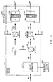
- FIG. 1 Depicted in FIG. 1 is an illustrative bistable optical device 100 having semiconductor multiple quantum well regions 101 and 102 for concomitantly maintaining two complementary and symmetric high and low absorption levels.
- the two complementary absorption levels of the device represent, for example, the two different logic levels of binary information.
- the information is obtained from or read out of the device by passing bias input light beams 160 and 161 through quantum well regions 101 and 102, respectively.
- the optical absorption of each quantum well region is at one of two different levels, for example, complementary high and low optical absorption levels. When the optical absorption of one of the two regions is at a high level, the optical absorption of the other region is at a low level.
- the transmission level of a light beam emitted from a quantum well region is reduced in proportion to the absorption level of the region. Accordingly, when the optical absorption of quantum well region 101 is at a high level, output light beam 162 emitted from the region is at a low transmission level. Since the optical absorption of quantum well region 102 is at a complementary low level, output light beam 163 emitted from the region is at a high transmission level.
- the state of the device is represented by the transmission level of one of the two output beams such as output light beam 163, whereas the complementary state of the device is represented by the transmission level of output light beam 162.
- complementary and symmetric output light beams 162 and 163 may be utilized to drive other complementary input optical devices used, for example, in a "dual-rail" optical logic system.
- the state of the device, as well as the complementary optical absorption levels of the quantum well regions changes when the difference in optical power applied to the two quantum well regions reaches a level depending on the optical power applied to the two regions.
- a ratio established by the power of light incident on quantum well region 101 relative to the power of the light incident on quantum well region 102 is greater than a first threshold value
- the complementary optical absorption levels of the two regions switch, and the state of the device changes.
- the optical power ratio is less than a second threshold value
- the optical absorption of the two regions switch back to its original complementary level.
- Optical device 100 comprises photodetectors 103 and 104 electrically interconnected via conductor 150.
- Each of photodetectors 103 and 104 is a well-known photodiode having n doped, intrinsic, and p doped layers, the n doped layer of photodiode 104 being electrically interconnected to the p doped layer of photodiode 103 via conductor 150.
- the intrinsic layer of photodiode 103 includes semiconductor multiple quantum well region 101.
- the intrinsic layer of photodiode 104 includes semiconductor multiple quantum well region 102.
- Photodiodes 103 and 104 are electrically connected in series with electric potential source 105 via conductors 151 and 152 to form an electrical circuit for electrically controlling the optical absorption of the quantum well regions.
- Source 105 is normally connected so as to reverse bias photodiodes 103 and 104. This requires that a positive voltage appear on the left of source 105 for the circuit as shown in FIG. 1. It is also possible to obtain useful characteristics from the device even though source 105 is omitted and replaced by a short circuit.
- input light beams 160 and 180 need not be incident on the same area on photodiodes 103, and input light beams 161 and 181 need not be incident on the same area on photodiode 104.
- Optical device 100 is similar to a self-electro-optic effect device; however, the self-electro-optic effect device does not have two semiconductor quantum well regions having complementary high and low optical absorption levels for emitting two complementary low and high transmission level output beams.
- the self-electro-optic effect device is described in an article by D. A. B. Miller et al., entitled “The Quantum Well Self Electro-Optic Effect Device; Optical Electronic Bistability and Oscillation, and Self-Linearized Modulation", IEEE Journal of Quantum Electronics, Vol. QE-21, September, 1985, pages 1462-1476 and further described in an article by D. A. B.
- FIG. 8 Shown in FIG. 8 is a cross-sectional view of device 100 in an integrated structure.
- This symmetric device includes p-i-n photodiodes 103 and 104 with respective quantum well regions 101 and 102 in the intrinsic layer.
- the material of the integrated structure was grown by molecular beam epitaxy on a Si doped n substrate.
- the multiple quantum well p-i-n diodes are made by etching separate mesas ( ⁇ 200X200 ⁇ m in this case) and electrically connecting two such mesas in series. Simultaneously fabricating the two diodes close to each other ensures nearly identical characteristics.
- Each of quantum well regions 101 and 102 consists of 63 periods of GaAs and A1GaAs 105 Angstroms and 80 Angstroms thick, respectively.
- the device structure as shown in FIG. 8 is designed with an additional diode structure formed from p regions 801 and 802, intrinsic region 803 and n regions 804, 805, and substrate 806.
- the substrate 806 and layer 805 are removed by chemical etching in the regions where beams 162 and 163 emerge so that beams 162 and 163 are not absorbed by the substrate or layer 805.
- the substrate is retained in at least one other portion of the device so that an electrical connection 807 may be made to the substrate.
- the electrical connection 807 is connected to the same positive potential as connection 151.
- the additional layers 803 and 804 are designed to be substantially transparent to beams 162 and 163.
- the junction of layers 803 and 804 is to provide electrical isolation between regions 801 and 802 while still allowing them to be grown on the same substrate 806.
- the isolation is enhanced by the connection of connection 807 to a positive potential as reverse biased diodes result.
- Other methods of isolation will be obvious to those skilled in the art, such as proton bombardment.
- a detailed layer structure from which the structure in FIG. 8 may be fabricated by well known etching, photolithographic, deposition and contacting techniques is shown in FIG. 9.
- Such a layer structure may be grown by molecular beam epitaxy.
- the value x refers to the mole fraction of aluminum in the compound AL x Ga 1- x As.
- the substrate 806 was doped with silicon during growth.
- a device constructed as in FIG. 8 and FIG. 9 showed bistable behavior for an input light wavelength of 855.8 nm. Fabrication of the two diodes 103 and 104 from the same material and adjacent to one another ensures nearly identical characteristics for these two diodes, which is advantageous in obtaining symmetrical operation.
- Photodiodes 103 and 104 are responsive to light beams 160 and 161, respectively, for generating a photocurrent in the electrical circuit formed by the two photodiodes and electric potential source 105.
- the two photodiodes electrically control the optical absorption of quantum well regions 101 and 102 by controlling the voltage across the two quantum well regions.
- the optical absorption of the quantum well regions varies as a function of the voltage across the region.
- Bistable optical device 100 changes from one state to the other by increasing the power of the light incident on one of photodiodes 103 and 104 relative to the power incident on the other photodiode. More particularly, when the ratio of the power of the light incident on one of the two photodiodes relative to the power of the light on the other photodiode is greater than a first predetermined threshold value, the optical absorption of the two quantum well regions changes to its complementary level. For example, when the ratio of the power of light beam 160 to light beam 161 is greater than the first predetermined threshold value, the optical absorption of quantum well region 102 changes from a high to a low level, and the optical absorption of quantum well region 101 concomitantly changes from a low to a high level.
- the optical absorption of the two quantum well regions will switch back to their initial complementary levels when the ratio of the power of light beam 162 relative to the power of light beam 161 is less than a second predetermined threshold value.
- the device is in a bistable operating region where it maintains its state prior to entering the bistable region.
- Another manner of changing the state of optical device 100 is to maintain light beams 160 and 161 at equivalent power levels and to apply one of either control light beams 180 and 181 to respective photodiodes 103 and 104.
- the power ratio of the light incident on the two photodiodes must be greater than the first threshold value or less than the second threshold value to cause the optical device to switch states. Accordingly, the combined power of light beam 160 and control beam 180 relative to the power of light beam 161 must exceed the first threshold to cause the optical device to switch states.
- the optical absorption of quantum well region 102 is determined by the attenuation of a light beam passing through the region.
- the optical absorption of quantum well region 102 is at a low level, thereby attenuating light beam 161 passing through the region and emitted as output light beam 163 a small amount such as 3db.
- the transmission level as well as the state of the device, of output light beam 163 is at a high transmission level.
- the optical absorption of quantum well region 101 is at a high level
- the transmission level of output light beam 162, as well as the complementary state of the device is at a low transmission level.
- a light beam passing through the region is attenuated a greater amount such as 6db.
- the optical absorption of the two quantum well regions will switch to their complementary absorption levels when the ratio of power incidented on the two photodiodes is less than the second predetermined threshold value.
- the transmission level of light beam 163 when the power of light beam 160 to the combined power of light beam 161 and control light beam 181 is less than the second predetermined threshold value, the transmission level of light beam 163, as well as the state of the device, will change from a high to a low.
- the transmission level of output light beam 162 as well as the complementary state of the device, will change from a low to a high.
- a light beam represents the combined optical power incident on a particular photodiode. Accordingly, a light beam may be the combination of one or more light beams.
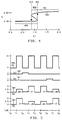
- Transmission level curve has a high transmission level portion 401 and a low transmission level portion 403 that overlap in bistable operating region 402 of the graph between input power ratio P1 straight lines 404 and 405.
- bistable region of the device a light beam emitted from the device in response to an input beam having a given power level is at one of two possible stable power levels.
- the operating history of the devices determines which one of the two levels the optical absorption or output light beam will assume.
- the transmission level of quantum well region Assuming the transmission level of quantum well region is initially at a low transmission level 403, the transmission level of the quantum well region, as well as the state of the device, will change to a high level when the power ratio P1 of input light beams 160 and 180 relative to input light beams 161 and 181 exceeds a first threshold value indicated by line 405 somewhere between 1.0 and 1.5 of power ratio P1. It is assumed that the responsivity of photodetectors 103 and 104 are equivalent. It has also been assumed for simplicity that the bistable region includes the ratio P1 equals 1.0. This ratio depends on the design of photodiodes 103 and 104, and when photodiodes 103 and 104 are not substantially identical, it may be necessary to use another ratio value as the operating point.
- quantum well region 102 maintains its high transmission level until the power ratio is less than a second threshold level indicated by straight line 404 somewhere between .5 and 1.0. This occurs when a ratio of power incident on the two photodiodes is less than a second threshold level which causes the quantum well to change from a high to a low transmission level. In low transmission level portion 403 of the curve, the optical absorption of quantum well region 102 is at a high level.
- the quantum well region 102 remains at its transmission level prior to entering the bistable region. For example, when the quantum well region 102 is at a high transmission level, it will remain in the high transmission level while in the bistable region. As the combined power of light beams 160 and 180 is decreased or the combined power of light beams 161 and 181 is increased, the power ratio will decrease until it reaches the second threshold level indicated by line 404. Below the second threshold value, the quantum well region 102 switches from a high to a low transmission level. Similarly, when the transmission level of the quantum level is low, it will remain in the low transmission level until the power ratio is greater than the first threshold value indicated by line 405.
- the transmission level curve of quantum well region 101 is the opposite of transmission level curve 400 of quantum well region 102.
- quantum well region 101 has a high transmission level portion over the same region as low transmission 403 of quantum well 102.
- Quantum well region 101 has a low transmission level portion over the same range of high transmission level portion 401 of region 102.
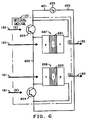
- FIG. 6 Depicted in FIG. 6 is another configuration of optical device 100.
- semiconductor multiple quantum well regions 601 and 602 are included in the intrinsic layer of respective structures 607 and 608 which are well-known photodiodes.
- Photodetectors 603 and 604 are electrically interconnected via conductor 650 and further connected in series with source of electric potential 605 via conductors 651 and 652.
- Photodetectors 603 and 604 are well-known phototransistors.
- Photodiodes 607 and 608 are electrically connected in parallel across respective phototransistors 603 and 604 as shown.
- Light beams 160 and 161 pass through respective quantum well regions 601 and 602 and are emitted as output light beams 162 and 163.
- Phototransistors 603 and 604 are responsive to respective control light beams 180 and 181 for electrically controlling the optical absorption of quantum well region 601 and 602.
- the operation of optical device 100 in this particular configuration is similar to that of the configuration of optical device 100 as shown in FIG. 1.
- the quantum well regions 601 and 602 are included in respective structures 607 and 608 separate and apart from photodetectors 603 and 604. However, the entire device could be easily integrated into a single structure.
- variable optical attenuator 701 concomitantly varying optical input beams 160 and 161 without changing the state of the device.
- concomitantly means substantially simultaneously.
- Variable optical attenuator 701 is a well-known and commercially available unit such as an acousto-optic modulator which is controllable by a suitable electrical control signal applied thereto on conductor 752 from a well-known electrical control circuit 702.
- Light beams 750 and 751 having equivalent power levels are applied to variable optical attenuator 701 and emitted as respective light beams 160 and 161.
- Attenuator 701 concomitantly increases the power level of input light beams 160 and 161 relative to that of 750 and 751 to read out the stored information at a high power level, thereby providing, in effect, optical power gain relative to either control light beams 180 and 181 which is useful in driving other optical devices.
- Device 100 will also retain its state when light beams 160 and 161 have been completely removed for a limited period of time such as at least ten seconds if the attenuator is operated as a shutter. Opening the shutter, device 100 would return to its state prior to the closing of the shutter.
- optical attenuator 701 concomitantly varies the power of light beams 750 and 751 so that emitted light beams 160 and 161 are attenuated by substantially equal fractions. Accordingly, the device remains in the same state over a substantial range of concomitantly varied power levels of light beams 160 and 161. As long as the power ratio of the two light beams remains between the first and second threshold values, device 100 will remain in its present state.
- Control beams 180 and 181 are treated as set (S) and reset (R) input signals to a S-R optical latch.
- FIG. 2 A modification version of the configuration of optical device 100 of FIG. 7 is shown in FIG. 2.
- light beams 160 and 161 from optical attenuator 701 are directed to optical combiners 200 and 201, respectively. These optical combiners are well-known and commercially available units.
- Control beams 180 and 181 are also applied to combiners 200 and 201, respectively.
- Optical combiner unit 200 combines bias light beams 160 and control beam 180 to form light beam 270 which has a power level equivalent of the sum of the power levels of the two light beams.
- optical combiner unit 201 combines bias light beam 161 and control light beam 181 to form light beam 271 having a power level equivalent to the sum of the power levels of the two beams.
- Light beams 270 and 271 are then applied to respective photodiodes 103 and 104 of the device as previously described.
- optical device 100 as shown in FIG. 2 may be further modified as shown in the illustrative embodiment of the invention in FIG. 3.
- well-known beam splitter 301 and an optical mirror 302 eliminate the need for two bias light beams being applied to optical attenuator 701.
- optical attenuator 703 variably attenuates a single input light beam 350 and directs the emitted light beam 351 to beam splitter 301.
- the beam splitter divides light beam 351 into light beams 160 and 161 in a ratio appropriate to bias the device in the bistable region.
- Beam splitter 301 directly transmits light beam 161 to optical combiner 201 which combines the beam with control light beam 181 to form light beam 271.
- Beam splitter 301 directs light beam 160 to optical combiner via mirror 302 as shown.
- Optical combiner 200 combines light beams 160 and 180 to form light beam 270.
- Optical device 100 includes the variable optical attenuator 701 as shown in the configuration in FIG. 7. As shown in FIG. 5, each of bias light beams 160 and 161 has two optical power levels consisting of zero and ten units. Variable optical attenuator 701 emits these signals in response to electrical control circuit 702. As shown, the two power levels of light beams 160 and 161 alternate between 0 and 10 units during alternate time periods.
- Each of set and reset control signals has two power levels consisting of 0 and 1 units.
- Output (Q) light beam 163 emitted from photodiode 104 and complementary output ( Q ) light beam 162 emitted from photodiode 103 have power levels consisting of 0, .25, .5, 2.5, and 5.0 as shown.
- the power level of light beams 160-163, 180 and 181 are all at 0. It will be assumed that the initial state of the device is at a low transmission with a complementary high transmission level state.
- bias light beams 160 and 161 assume and maintain a power level of ten units
- output (Q) light beam 163 assumes and maintains a power level of 2.5 units representative of a low transmission level.
- Complementary output ( Q ) light beam 162 assumes and maintains a power level of 5.0 units indicative of a high transmission level.
- optical bias beams 160 and 161 maintain to a 0 power level, and the power level of set (S) control light beam 180 changes to 1.0 units.
- the state of the device changes to its complementary level, indicated by output (Q) light beam 163 exponentially changing from a level of .25 to .50 power units.
- the power level of complementary output ( Q ) light beam 162 changes from .5 to .25 units.
- the state of the device and the stored information is obtained or read out of the device.
- the power level of bias light beams 160 and 161 concomitantly change to 10 units.
- the power level of output light beams 162 and 163 changes to 2.5 and 5.0 units, respectively.
- the transmission level of the output beams 162 and 163 indicate that the complementary states of the device have changed.
- reset (R) control light beam 181 changes to 1.0 power units for resetting the state of the device back to its initially assumed state.
- output (Q) light beam 163 exponentially changes from .50 to .25 power units
- complementary output ( Q ) light beam 162 changes from .25 to .5 power units.
- bias light beams 160 and 161 once again assume a high power level to obtain the state of the device.
- Output (Q) light beam 163 assumes a low transmission power level at 2.5 units
- complementary output (Q) light beam 162 assumes a high transmission power level at 5.0 units.
- optical device is merely an illustrative embodiment of the principles of this invention and that numerous other optical devices may be devised by those skilled in the art without departing from the scope of the invention.
- one skilled in the art may develop a number of other optical memory devices using several multiple quantum well regions for producing complementary output high and low level output light beams.
Landscapes
- Physics & Mathematics (AREA)
- Chemical & Material Sciences (AREA)
- Optics & Photonics (AREA)
- Engineering & Computer Science (AREA)
- Nanotechnology (AREA)
- Nonlinear Science (AREA)
- Life Sciences & Earth Sciences (AREA)
- Biophysics (AREA)
- General Physics & Mathematics (AREA)
- Crystallography & Structural Chemistry (AREA)
- Photo Coupler, Interrupter, Optical-To-Optical Conversion Devices (AREA)
- Optical Communication System (AREA)
- Semiconductor Lasers (AREA)
Claims (5)
- Optische Vorrichtung (100) mit
einer ersten Einrichtung (103) mit einem ersten Halbleiter-Quantendrogbereich (101), wobei die erste Einrichtung in Antwort auf einen ersten auf diese einfallenden Lichtstrahl (160) einen Fotostrom zum elektrischen Steuern der optischen Absorption des ersten Quantendrogbereiches erzeugt und
einer zweiten Einrichtung (104) mit einem zweiten Halbleiter-Quantendrogbereich (102), wobei die zweite Einrichtung in Antwort auf einen zweiten auf diese einfallenden Lichtstrahl (161) einen Fotostrom zum elektrischen Steuern der optischen Absorption des zweiten Quantendrogbereiches erzeugt,
wobei die erste und zweite Einrichtung jeweils eine erste und eine zweite p-i-n-Fotodiode enthalten, die jede einen p-dotierten Bereich, einen den jeweiligen Quantendrogbereich enthaltenden intrinsischen Bereich und einen n-dotierten Bereich hat,
dadurch gekennzeichnet, daß
der p-dotierte Bereich der ersten Fotodiode mit dem n-dotierten Bereich der zweiten Fotodiode verbunden ist,
und daß die Einrichtung weiter enthält:
eine Einrichtung (151) zum elektrischen Verbinden des n-dotierten Bereichs der ersten Fotodiode mit einem ersten Anschluß einer Spannungsquelle (105) und
eine Einrichtung (152) zum elektrischen Verbinden des p-dotierten Bereichs der zweiten Fotodiode mit einem zweiten Anschluß der Spannungsquelle, wobei die optische Absorption des ersten Quantendrogbereiches einen ersten vorbestimmten Pegel annimmt und die optische Absorption des zweiten Quantendrogbereiches begleitend einen zweiten vorbestimmten Pegel annimmt, wenn das Verhältnis der Leistung des ersten zu dem zweiten Lichtstrahl größer als ein erster vorbestimmter Wert ist, und die optische Absorption des ersten Quantendrogbereiches den zweiten vorbestimmten Pegel annimmt und die optische Absorption des zweiten Quantendrogbereiches den ersten vorbestimmten Pegel annimmt, wenn das Verhältnis kleiner als ein zweiter vorbestimmter Wert ist, der geringer als der erste vorbestimmte Wert ist. - Optische Vorrichtung nach Anspruch 1,
dadurch gekennzeichnet, daß die Vorrichtung weiter enthält: einen ersten Fototransistor (603), der in Antwort auf einen auf diesen einfallenden Lichtstrahl (180) einen Fotostrom erzeugt und einen mit dem p-dotierten Bereich der ersten Fotodiode verbundenen Emitter hat und einen mit dem n-dotierten Bereich der ersten Fotodiode verbundenen Kollektor hat; einen zweiten Fototransistor (604), der in Antwort auf einen auf diesen einfallenden vierten Lichtstrahl (181) einen Fotostrom erzeugt und einen mit dem p-dotierten Bereich der zweiten Fotodiode verbundenen Emitter hat und einen mit dem n-dotierten Bereich der zweiten Fotodiode verbundenen Kollektor hat. - Optische Vorrichtung nach Anspruch 1,
dadurch gekennzeichnet, daß
die erste Einrichtung ferner in Antwort auf einen auf diese einfallenden dritten Lichtstrahl (180) einen Fotostrom erzeugt, die zweite Einrichtung ferner in Antwort auf einen auf diese einfallenden vierten Lichtstrahl (181) einen Fotostrom erzeugt, die optische Absorption des ersten Quantendrogbereiches den ersten, einen ersten Zustand der Einrichtung darstellenden vorbestimmten Pegel annimmt und die optische Absorption des zweiten Quantendrogbereiches begleitend den zweiten, ebenfalls den ersten Zustand der Einrichtung darstellenden Pegel annimmt, wenn ein Verhältnis der gesamten Leistung des ersten und dritten Strahls zu der gesamten Leistung des zweiten und vierten Strahls größer als der erste vorbestimmte Wert ist und die optische Absorption des ersten Quantendrogbereiches den zweiten einen zweiten Zustand der Einrichtung darstellenden vorbestimmten Pegel annimmt und die optische Absorption des zweiten Quantendrogbereiches begleitend den ersten vorbestimmten ebenfalls den zweiten Zustand der Einrichtung darstellenden Zustand annimmt, wenn das Verhältnis der gesamten Leistung des ersten und des dritten Strahls zu der gesamten Leistung des zweiten und des vierten Strahls kleiner ist als der zweite vorbestimmte Wert. - Optische Vorrichtung nach Anspruch 2 oder 3,
dadurch gekennzeichnet, daß
die Vorrichtung weiterhin eine Einrichtung (701) für das gemeinsame Verändern des ersten und zweiten Lichtstrahls enthält,
der dritte und vierte Lichtstrahl für das Setzen des Zustands der Einrichtung vorgesehen ist, wenn das gesamte Leistungsverhältnis größer als der erste vorbestimmte Wert ist und wenn das gesamte Leistungsverhältnis kleiner als der zweite vorbestimmte Wert ist und
daß der erste und zweite Lichtstrahl für das Lesen des Zustands der Einrichtung vorgesehen ist, wenn das gesamte Leistungsverhältnis kleiner als der erste vorbestimmte Wert, aber ebenfalls größer als der zweite vorbestimmte Wert ist. - Anordnung mit einer optischen Vorrichtung nach Anspruch 4 und einer zeitlichen Steuereinrichtung zum Steuern des ersten, zweiten, dritten und vierten Lichtstrahls, derart, daß entweder der dritte oder vierte Lichtstrahl angelegt wird, um den Zustand der Einrichtung zu setzen, und der erste und zweite Lichtstrahl danach simultan angelegt wird, um den Zustand der Einrichtung in einer zeitlich aufeinanderfolgenden Weise auszulesen.
Applications Claiming Priority (2)
| Application Number | Priority Date | Filing Date | Title |
|---|---|---|---|
| US07/042,411 US4754132A (en) | 1987-04-24 | 1987-04-24 | Symmetric optical device with quantum well absorption |
| US42411 | 1987-04-24 |
Publications (2)
| Publication Number | Publication Date |
|---|---|
| EP0360833A1 EP0360833A1 (de) | 1990-04-04 |
| EP0360833B1 true EP0360833B1 (de) | 1993-05-19 |
Family
ID=21921787
Family Applications (1)
| Application Number | Title | Priority Date | Filing Date |
|---|---|---|---|
| EP88905471A Expired - Lifetime EP0360833B1 (de) | 1987-04-24 | 1988-02-26 | Symmetrische optische vorrichtung |
Country Status (6)
| Country | Link |
|---|---|
| US (1) | US4754132A (de) |
| EP (1) | EP0360833B1 (de) |
| JP (1) | JP2650746B2 (de) |
| CA (1) | CA1298388C (de) |
| DE (1) | DE3881212T2 (de) |
| WO (1) | WO1988008553A2 (de) |
Families Citing this family (32)
| Publication number | Priority date | Publication date | Assignee | Title |
|---|---|---|---|---|
| US4830444A (en) * | 1987-12-31 | 1989-05-16 | American Telephone And Telegraph Company, At&T Bell Laboratories | Optical switch |
| US4800262A (en) * | 1987-12-31 | 1989-01-24 | American Telephone And Telegraph Company, At&T Bell Laboratories | Tri-state optical device with quantum well absorption |
| US4952791A (en) * | 1988-12-12 | 1990-08-28 | At&T Bell Laboratories | Monolithic apparatus comprising optically interconnected quantum well devices |
| US4904859A (en) * | 1989-01-17 | 1990-02-27 | American Telephone And Telegraph Company | Self electrooptic effect device employing asymmetric quantum wells |
| US4985621A (en) * | 1989-04-11 | 1991-01-15 | Massachusetts Institute Of Technology | Electrooptical switch with separate detector and modulator modules |
| US4914286A (en) * | 1989-04-20 | 1990-04-03 | At&T Bell Laboratories | Method and apparatus for increasing the processing capacity of optical digital processing systems having optically bistable devices |
| US4978842A (en) * | 1989-04-21 | 1990-12-18 | At&T Bell Laboratories | Programmable optical logic device with complementary inputs |
| EP0395063A3 (de) * | 1989-04-27 | 1991-09-11 | Tsentr Nauchno-Tekhnicheskogo Tvorchestva Molodezhi " Linax" | Bistabiler optischer Trigger |
| US5036512A (en) * | 1989-05-08 | 1991-07-30 | At&T Bell Laboratories | Optical apparatus for combining light beam arrays having different wavelengths |
| US4904858A (en) * | 1989-05-31 | 1990-02-27 | American Telephone And Telegraph Company | Programmable optical logic devices operable by measuring the ratio of optical data signal power to optical reference threshold power |
| US4959534A (en) * | 1989-08-28 | 1990-09-25 | At&T Bell Laboratories | Differential optical logic arrangement |
| US4967068A (en) * | 1989-08-28 | 1990-10-30 | At&T Bell Laboratories | Single-ended optical logic arrangement |
| DE69112235T2 (de) * | 1990-01-23 | 1996-06-13 | Nippon Telegram & Telephone | Optisches Gate-Array. |
| US5093565A (en) * | 1990-07-18 | 1992-03-03 | At&T Bell Laboratories | Apparatus for sequential optical systems where an independently controllable transmission gate is interposed between successive optoelectronic gates |
| US5126553A (en) * | 1990-11-28 | 1992-06-30 | Bell Communications Research, Inc. | Bistable optically switchable resonant-tunneling device and its use in signal processing |
| US5130528A (en) * | 1991-03-01 | 1992-07-14 | International Business Machines Corporation | Opto-photo-electric switch |
| US5198656A (en) * | 1991-06-06 | 1993-03-30 | At&T Bell Laboratories | Dynamic optical logic using voltage pull up |
| US5238867A (en) * | 1991-07-09 | 1993-08-24 | Posco Educational Foundation | Method for preparing an optical switching device having multiple quantum wells |
| US5233184A (en) * | 1991-12-27 | 1993-08-03 | At&T Bell Laboratories | Matrix addressed S-SEED optical modulator array |
| US5251052A (en) * | 1992-09-02 | 1993-10-05 | The United States Of America As Represented By The Secretary Of The Navy | System for solving boolean equations using optical lookup tables |
| US5288990A (en) * | 1992-12-28 | 1994-02-22 | At&T Bell Laboratories | Differential self-electrooptic effect device |
| US5311008A (en) * | 1992-12-28 | 1994-05-10 | At&T Bell Laboratories | Self-electrooptic effect device for providing integer gain to input optical signals having series connected quantum well diodes |
| US5343032A (en) * | 1993-04-08 | 1994-08-30 | At&T Bell Laboratories | Diode-clamped optical receiver |
| US5543631A (en) * | 1993-06-17 | 1996-08-06 | Weinberger; Lester | Hybrid organic-inorganic bistable nonlinear optical gate |
| JP3009562B2 (ja) * | 1993-07-30 | 2000-02-14 | 三菱電機株式会社 | 光スイッチング装置 |
| US5483186A (en) * | 1994-05-05 | 1996-01-09 | At&T Corp. | Push-pull optical modulator driver circuit |
| KR0148597B1 (ko) * | 1994-11-23 | 1998-10-15 | 정선종 | 왜곡 성장층을 이용한 금속/반도체 접합 쇼트키 다이오드 광소자 |
| US5483375A (en) * | 1994-12-14 | 1996-01-09 | At&T Corp. | Optical ratio amplifier |
| US6636681B2 (en) * | 2001-05-07 | 2003-10-21 | Photonport Technologies, Inc. | Optical attenuator |
| US7218858B1 (en) | 2002-05-20 | 2007-05-15 | Ciena Corporation | System and method for use of a variable optical attenuator in an optical network |
| CN101657902B (zh) * | 2007-04-13 | 2012-01-11 | 夏普株式会社 | 光传感器和显示装置 |
| US10092396B2 (en) | 2015-12-14 | 2018-10-09 | Novartis Ag | Flexible, hermetic electrical interconnect for electronic and optoelectronic devices for in vivo use |
Citations (1)
| Publication number | Priority date | Publication date | Assignee | Title |
|---|---|---|---|---|
| US456244A (en) * | 1891-07-21 | Shaking attachment for rocking grates |
Family Cites Families (5)
| Publication number | Priority date | Publication date | Assignee | Title |
|---|---|---|---|---|
| US3753247A (en) * | 1971-04-22 | 1973-08-14 | Rca Corp | Array of devices responsive to differential light signals |
| US4166224A (en) * | 1977-06-17 | 1979-08-28 | Hutson Jerald L | Photosensitive zero voltage semiconductor switching device |
| US4546244A (en) * | 1984-03-14 | 1985-10-08 | At&T Bell Laboratories | Nonlinear and bistable optical device |
| US4691111A (en) * | 1984-04-05 | 1987-09-01 | The United States Of America As Represented By The Secretary Of The Army | Multiple gap optically activated switch |
| DE3683370D1 (de) * | 1985-10-08 | 1992-02-20 | American Telephone & Telegraph | Nichtlineares und bistabiles optisches bauelement. |
-
1987
- 1987-04-24 US US07/042,411 patent/US4754132A/en not_active Expired - Lifetime
-
1988
- 1988-02-26 DE DE8888905471T patent/DE3881212T2/de not_active Expired - Fee Related
- 1988-02-26 WO PCT/US1988/000459 patent/WO1988008553A2/en not_active Ceased
- 1988-02-26 EP EP88905471A patent/EP0360833B1/de not_active Expired - Lifetime
- 1988-02-26 JP JP63505124A patent/JP2650746B2/ja not_active Expired - Lifetime
- 1988-03-28 CA CA000562647A patent/CA1298388C/en not_active Expired - Fee Related
Patent Citations (1)
| Publication number | Priority date | Publication date | Assignee | Title |
|---|---|---|---|---|
| US456244A (en) * | 1891-07-21 | Shaking attachment for rocking grates |
Also Published As
| Publication number | Publication date |
|---|---|
| CA1298388C (en) | 1992-03-31 |
| DE3881212T2 (de) | 1993-09-02 |
| EP0360833A1 (de) | 1990-04-04 |
| WO1988008553A2 (en) | 1988-11-03 |
| DE3881212D1 (de) | 1993-06-24 |
| JP2650746B2 (ja) | 1997-09-03 |
| WO1988008553A3 (en) | 1988-12-01 |
| JPH02503720A (ja) | 1990-11-01 |
| US4754132A (en) | 1988-06-28 |
Similar Documents
| Publication | Publication Date | Title |
|---|---|---|
| EP0360833B1 (de) | Symmetrische optische vorrichtung | |
| EP0359778B1 (de) | Optische vorrichtung | |
| US5625636A (en) | Integration of photoactive and electroactive components with vertical cavity surface emitting lasers | |
| JP2637531B2 (ja) | 光スイッチ | |
| US5056098A (en) | Vertical cavity laser with mirror having controllable reflectivity | |
| US4829357A (en) | PNPN thyristor | |
| US4689793A (en) | Optical logic and memory apparatus | |
| US4833511A (en) | Phototransistor device | |
| JPH0583123A (ja) | 光通信論理素子部品 | |
| US4518934A (en) | Optical bistable device | |
| Chirovsky et al. | Batch-fabricated symmetric self-electro-optic effect devices | |
| US5677552A (en) | Optical control circuit for an optical pnpn thyristor | |
| US4822992A (en) | Wavelength conversion using self electrooptic effect devices | |
| US5742045A (en) | Apparatus using diode laser logic to form a configurable optical gate system | |
| US4967068A (en) | Single-ended optical logic arrangement | |
| US5541443A (en) | Active optical logic device incorporating a surface-emitting laser | |
| US5107307A (en) | Semiconductor device for control of light | |
| Taylor et al. | Integrated inversion channel optoelectronic devices and circuit elements for multifunctional array applications | |
| Lu et al. | Binary optical switch and programmable optical logic gate based on the integration of GaAs/AlGaAs surface-emitting lasers and heterojunction phototransistors | |
| US5325387A (en) | Method of operating a semiconductor laser as a bistable opto-electronic component | |
| Zhou et al. | Surface‐emitting laser‐based optical bistable switching device | |
| US5343032A (en) | Diode-clamped optical receiver | |
| Wheatley et al. | Hard limiting opto-electronic logic devices | |
| Zouganeli et al. | Symmetric self-electro-optic effect device using symmetric-cavity quantum well electroabsorption modulators | |
| JPH0667244A (ja) | 半導体光微分器 |
Legal Events
| Date | Code | Title | Description |
|---|---|---|---|
| PUAI | Public reference made under article 153(3) epc to a published international application that has entered the european phase |
Free format text: ORIGINAL CODE: 0009012 |
|
| 17P | Request for examination filed |
Effective date: 19891017 |
|
| AK | Designated contracting states |
Kind code of ref document: A1 Designated state(s): DE FR GB IT NL SE |
|
| 17Q | First examination report despatched |
Effective date: 19911125 |
|
| GRAA | (expected) grant |
Free format text: ORIGINAL CODE: 0009210 |
|
| AK | Designated contracting states |
Kind code of ref document: B1 Designated state(s): DE FR GB IT NL SE |
|
| REF | Corresponds to: |
Ref document number: 3881212 Country of ref document: DE Date of ref document: 19930624 |
|
| ET | Fr: translation filed | ||
| ITF | It: translation for a ep patent filed | ||
| PLBE | No opposition filed within time limit |
Free format text: ORIGINAL CODE: 0009261 |
|
| STAA | Information on the status of an ep patent application or granted ep patent |
Free format text: STATUS: NO OPPOSITION FILED WITHIN TIME LIMIT |
|
| 26N | No opposition filed | ||
| EAL | Se: european patent in force in sweden |
Ref document number: 88905471.4 |
|
| PGFP | Annual fee paid to national office [announced via postgrant information from national office to epo] |
Ref country code: SE Payment date: 20001227 Year of fee payment: 14 |
|
| PGFP | Annual fee paid to national office [announced via postgrant information from national office to epo] |
Ref country code: FR Payment date: 20010123 Year of fee payment: 14 |
|
| PGFP | Annual fee paid to national office [announced via postgrant information from national office to epo] |
Ref country code: GB Payment date: 20010125 Year of fee payment: 14 |
|
| PGFP | Annual fee paid to national office [announced via postgrant information from national office to epo] |
Ref country code: NL Payment date: 20010129 Year of fee payment: 14 |
|
| PGFP | Annual fee paid to national office [announced via postgrant information from national office to epo] |
Ref country code: DE Payment date: 20010330 Year of fee payment: 14 |
|
| REG | Reference to a national code |
Ref country code: GB Ref legal event code: IF02 |
|
| PG25 | Lapsed in a contracting state [announced via postgrant information from national office to epo] |
Ref country code: GB Free format text: LAPSE BECAUSE OF NON-PAYMENT OF DUE FEES Effective date: 20020226 |
|
| PG25 | Lapsed in a contracting state [announced via postgrant information from national office to epo] |
Ref country code: SE Free format text: LAPSE BECAUSE OF NON-PAYMENT OF DUE FEES Effective date: 20020227 |
|
| PG25 | Lapsed in a contracting state [announced via postgrant information from national office to epo] |
Ref country code: NL Free format text: LAPSE BECAUSE OF NON-PAYMENT OF DUE FEES Effective date: 20020901 |
|
| PG25 | Lapsed in a contracting state [announced via postgrant information from national office to epo] |
Ref country code: DE Free format text: LAPSE BECAUSE OF NON-PAYMENT OF DUE FEES Effective date: 20020903 |
|
| EUG | Se: european patent has lapsed |
Ref document number: 88905471.4 |
|
| GBPC | Gb: european patent ceased through non-payment of renewal fee |
Effective date: 20020226 |
|
| PG25 | Lapsed in a contracting state [announced via postgrant information from national office to epo] |
Ref country code: FR Free format text: LAPSE BECAUSE OF NON-PAYMENT OF DUE FEES Effective date: 20021031 |
|
| NLV4 | Nl: lapsed or anulled due to non-payment of the annual fee |
Effective date: 20020901 |
|
| REG | Reference to a national code |
Ref country code: FR Ref legal event code: ST |
|
| PG25 | Lapsed in a contracting state [announced via postgrant information from national office to epo] |
Ref country code: IT Free format text: LAPSE BECAUSE OF NON-PAYMENT OF DUE FEES;WARNING: LAPSES OF ITALIAN PATENTS WITH EFFECTIVE DATE BEFORE 2007 MAY HAVE OCCURRED AT ANY TIME BEFORE 2007. THE CORRECT EFFECTIVE DATE MAY BE DIFFERENT FROM THE ONE RECORDED. Effective date: 20050226 |