EP0360460A1 - Flow switches - Google Patents
Flow switches Download PDFInfo
- Publication number
- EP0360460A1 EP0360460A1 EP89309056A EP89309056A EP0360460A1 EP 0360460 A1 EP0360460 A1 EP 0360460A1 EP 89309056 A EP89309056 A EP 89309056A EP 89309056 A EP89309056 A EP 89309056A EP 0360460 A1 EP0360460 A1 EP 0360460A1
- Authority
- EP
- European Patent Office
- Prior art keywords
- flow
- bore
- flow switch
- shuttle
- switch according
- Prior art date
- Legal status (The legal status is an assumption and is not a legal conclusion. Google has not performed a legal analysis and makes no representation as to the accuracy of the status listed.)
- Granted
Links
Images

Classifications
-
- H—ELECTRICITY
- H01—ELECTRIC ELEMENTS
- H01H—ELECTRIC SWITCHES; RELAYS; SELECTORS; EMERGENCY PROTECTIVE DEVICES
- H01H35/00—Switches operated by change of a physical condition
- H01H35/24—Switches operated by change of fluid pressure, by fluid pressure waves, or by change of fluid flow
- H01H35/40—Switches operated by change of fluid pressure, by fluid pressure waves, or by change of fluid flow actuated by devices allowing continual flow of fluid, e.g. vane
- H01H35/405—Switches operated by change of fluid pressure, by fluid pressure waves, or by change of fluid flow actuated by devices allowing continual flow of fluid, e.g. vane the switch being of the reed switch type
Definitions
- This invention relates to flow switches, that is to switches for detecting flow of a fluid.
- UK Patent Application No. GB-A-2 189 648 discloses an offset-type flow switch in which the inlet and outlet passages are not collinear.
- the float member is disposed in an extension of the inlet passage and moves as a result of fluid pressure to expose a slot between the inlet and outlet passages.
- the offset nature of the arrangement means that the flow switch cannot readily be incorporated in an existing installation.
- the inlet and the outlet connections must be provided in a correspondingly offset manner.
- a flow switch comprising: a body with a bore extending therethrough, the bore having relatively narrower and wider sections; a member movable within the narrower and wider sections of the bore such that the member is a relatively close fit in the narrower bore section, the member having a first portion which permits only limited fluid flow in the close fit clearance between the first portion and the narrower bore section, and a second portion having a flow bypass arrangement whereby substantial fluid flow is possible with the second portion located in the narrower bore section, the member being movable by fluid flow from a closed position to an open position, wherein in the closed position, both the second portion and at least part of the first portion are within the narrower bore section, whereas in the open position, the first portion and a part of the second portion are within the wider bore section thereby allowing fluid to flow; and means for detecting whether the member is in the open position or the closed position.
- the bore sections and the member are both generally cylindrical, with the first portion being a solid cylinder and the second portion being a solid cylinder of reduced diameter, vanes or fins making up the difference to the diameter of the first portion; thus the flow bypass arrangement is constituted by the vanes of the second portion of the member, since fluid can flow through the spaces between the vanes.
- the detecting means is preferably a magnetic arrangement, such as a reed switch or a Hall-effect sensor.
- the member is either made of magnetised material or incorporates a separate magnet within it.
- other detecting means such as capacitive sensors, optical detectors or the like may be used instead.
- a flow switch comprises a body 10 having a bore made up of first to fourth sections 12, 14, 16, 18, the first section 12 defining an inlet, the second and third sections 14, 16 defining a shuttle housing area, and the fourth section 18 defining an outlet.
- the first and fourth sections 12, 18 are preferably of the same internal diameter, which may typically be equal to the internal diameter of the piping system being used, for example 15 mm copper pipe.
- the second section 14 has a larger internal diameter
- the third section 16 has a still larger internal diameter.
- the first and second sections 12, 14 have a connecting portion 20 of part-conical section; similarly, the second and third sections 14, 16 also have a connecting portion 22 of part-conical section.
- the third and fourth sections 16, 18 have a baffled connection portion 24 which includes a restriction of part-conical section with baffle parts projecting into the bore so as to form a shuttle retaining means.
- the body 10 may be formed of a suitable metal, plastics material or the like.
- a shuttle 30 is housed within the second and third sections 14, 16 of the bore.
- the shuttle 30 includes a solid cylindrical section 32 and a vaned section 34.
- the vaned section 34 is formed of a solid cylindrical section of reduced diameter with a number of (for example, four, six or eight) vanes or fins extending from the reduced-diameter solid cylindrical section.
- the dimensions of the vanes are such that the effective diameter of a circle forming a locus of the vaned section 34 is the same as the diameter of the solid cylindrical section 32.
- the shuttle 30 is either made of magnetised material or else includes within its body an internal magnet.
- a detector housing 40 is mounted on the outside of the body 10, preferably adjacent the second section 14 of the bore, as shown.
- the detector housing 40 includes a magnetic sensing means, such as a reed switch (not shown) within the housing, contacts 42 being provided for electrical connection to an external circuit.
- a magnetic sensing means such as a reed switch (not shown) within the housing, contacts 42 being provided for electrical connection to an external circuit.
- a flow switch embodying the invention as described above has the advantages that, in its open state, it can present minimal obstruction to fluid flow and, in its closed state, it can allow a certain amount of reverse flow seepage thus permitting fluid drainage back to the inlet side of the flow switch.
- the flow switch illustrated in Figures 1 and 2 is intended for vertical mounting whereby the closed position of the shuttle as shown in Figure 1 is effected by gravity. If it is desired to operate the flow switch in some other orientation, a spring may be included to provide the shuttle with a bias towards the inlet such that the shuttle remains in the closed position unless the bias is overcome by a force from fluid flow.
Abstract
Description
- This invention relates to flow switches, that is to switches for detecting flow of a fluid.
- In certain applications, it is necessary to detect that a fluid such as a liquid is flowing and to provide an electrical signal dependent thereon. One such application is in shower systems having a pump for providing sufficient pressure to operate the shower, in installations providing an inadequate head of water. Depending on whether the pump is operating or not, and whether or not the water tap has been opened, flow of water may or may not be taking place, and it is necessary to provide an indication of flow to ensure proper control and to prevent possible damage to the installation.
- It has been proposed, for example in UK Patent Nos. GB-A-1 360 225, GB-A-1 496 601 and GB-A-1 604 247, to provide a flow switch in the form of a housing within which a magnetised float member can move between one position in which flow is either not occurring or is being initiated from an undesired direction, and another position to which the float member is moved by fluid flow from a desired direction, the other position allowing fluid flow through the flow switch. A magnetically-responsive switch, such as a reed switch, is positioned to detect the position of the float member such that a flow detect signal is provided when the float member is in the other position.
- A problem with the previously-proposed flow switches is that the design has led to the float member and corresponding parts of the internal bore of the flow switch providing a significant obstruction to the fluid flow. This is particularly disadvantageous since, in many applications of the flow switch, the source of fluid pressure may be unreliable and periodically insufficient; in such a case, it is clearly undesirable to cut down the available pressure still further by obstruction of whatever flow could otherwise be obtained.
- Another problem with some previously-proposed flow switches is that the design effectively provides a seal against reverse flow, the float member seating against a corresponding surface of the bore. Whereas in general it is not required for the flow switch to allow a substantial fluid flow in the reverse direction, in many applications it should be possible for fluid to return to the inlet side of the flow switch, in other words a certain degree of fluid seepage should be permitted. Otherwise, for example, a column of water may be trapped above a vertically-disposed flow switch which is closed, and if this column of water is tall enough, it will affect operation of the float member on which it is acting.
- UK Patent Application No. GB-A-2 189 648 discloses an offset-type flow switch in which the inlet and outlet passages are not collinear. The float member is disposed in an extension of the inlet passage and moves as a result of fluid pressure to expose a slot between the inlet and outlet passages. The offset nature of the arrangement means that the flow switch cannot readily be incorporated in an existing installation. The inlet and the outlet connections must be provided in a correspondingly offset manner.
- According to the present invention there is provided a flow switch comprising:
a body with a bore extending therethrough, the bore having relatively narrower and wider sections;
a member movable within the narrower and wider sections of the bore such that the member is a relatively close fit in the narrower bore section, the member having a first portion which permits only limited fluid flow in the close fit clearance between the first portion and the narrower bore section, and a second portion having a flow bypass arrangement whereby substantial fluid flow is possible with the second portion located in the narrower bore section, the member being movable by fluid flow from a closed position to an open position, wherein in the closed position, both the second portion and at least part of the first portion are within the narrower bore section, whereas in the open position, the first portion and a part of the second portion are within the wider bore section thereby allowing fluid to flow; and
means for detecting whether the member is in the open position or the closed position. - In a preferred embodiment of the invention, to be described in greater detail hereinafter, the bore sections and the member are both generally cylindrical, with the first portion being a solid cylinder and the second portion being a solid cylinder of reduced diameter, vanes or fins making up the difference to the diameter of the first portion; thus the flow bypass arrangement is constituted by the vanes of the second portion of the member, since fluid can flow through the spaces between the vanes.
- The detecting means is preferably a magnetic arrangement, such as a reed switch or a Hall-effect sensor. In that case, the member is either made of magnetised material or incorporates a separate magnet within it. However, other detecting means such as capacitive sensors, optical detectors or the like may be used instead.
- The invention will now be described by way of example with reference to the accompanying drawings, throughout which like parts are referred to by like references, and in which:
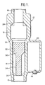
- Figure 1 is a cross-sectional view through a flow switch according to an embodiment of the invention, the flow switch being in a closed state; and
- Figure 2 is a cross-sectional view similar to that of Figure 1, but with the flow switch in an open state.
- Referring to Figures 1 and 2, a flow switch comprises a
body 10 having a bore made up of first tofourth sections first section 12 defining an inlet, the second andthird sections fourth section 18 defining an outlet. The first andfourth sections second section 14 has a larger internal diameter, and thethird section 16 has a still larger internal diameter. The first andsecond sections portion 20 of part-conical section; similarly, the second andthird sections portion 22 of part-conical section. Finally, the third andfourth sections connection portion 24 which includes a restriction of part-conical section with baffle parts projecting into the bore so as to form a shuttle retaining means. Thebody 10 may be formed of a suitable metal, plastics material or the like. - A
shuttle 30 is housed within the second andthird sections shuttle 30 includes a solidcylindrical section 32 and avaned section 34. Thevaned section 34 is formed of a solid cylindrical section of reduced diameter with a number of (for example, four, six or eight) vanes or fins extending from the reduced-diameter solid cylindrical section. Preferably the dimensions of the vanes are such that the effective diameter of a circle forming a locus of thevaned section 34 is the same as the diameter of the solidcylindrical section 32. Theshuttle 30 is either made of magnetised material or else includes within its body an internal magnet. - A
detector housing 40 is mounted on the outside of thebody 10, preferably adjacent thesecond section 14 of the bore, as shown. Thedetector housing 40 includes a magnetic sensing means, such as a reed switch (not shown) within the housing,contacts 42 being provided for electrical connection to an external circuit. As in previously-proposed apparatus, fluid flow causes movement of theshuttle 30, the resulting change in magnetic field causing the magnetic sensing means to respond. Thus it is possible to detect fluid flow in one direction. - The operation of the flow switch will now be described in more detail.
- Firstly, referring to Figure 1, there will be described the situation in which there is no flow from the inlet (first section 12) to the outlet (fourth section 18). In that case, the
shuttle 30 rests under gravity with a bottom flared end of thevaned section 34 resting against the restriction formed by theconnection portion 20. It is important to note that there is no seal at this point; thus, although substantial reverse flow cannot take place due to the relatively close fit between the solidcylindrical section 32 of theshuttle 30 and thesecond section 14 of the bore, downward seepage of liquid can take place to a limited extent. Thus, it is possible for residual liquid remaining above the flow switch to drain downwardly, which is an important advantage in particular applications. In the position of theshuttle 30 shown in Figure 1, the magnetic sensing means within thedetector housing 40 is in a first state. If, for example, a reed switch is used, the switch may be in a conductive state. - Secondly, referring to Figure 2, there will be described the situation in which there is fluid flow from the inlet (first section 12) to the outlet (fourth section 18). In this open state, the
shuttle 30 is lifted by fluid pressure until, if the fluid flow is sufficient, it is retained against the baffle parts of the connectingportion 24. Obstruction to flow is minimised, firstly by virtue of the vanes of thevaned section 34 permitting substantial fluid flow when thevaned section 34 is within thethird section 16 of the bore, and secondly as a result of the baffle parts of the connectingportion 24 holding theshuttle 30 clear of the bore. It has been found that the configuration of bore and shuttle shown in Figures 1 and 2 can readily be designed such that the flow area at any point along the bore, irrespective of the position of the shuttle, is not less than the area of thefirst section 12 forming the flow switch inlet; under these conditions, the friction losses during full flow are minimised to less than 10%. In the open position of theshuttle 30, the magnetic sensing means is in a second state; in the case of a reed switch, the switch may be non-conductive. - Accordingly, a flow switch embodying the invention as described above has the advantages that, in its open state, it can present minimal obstruction to fluid flow and, in its closed state, it can allow a certain amount of reverse flow seepage thus permitting fluid drainage back to the inlet side of the flow switch. The fact that the diameter of the shuttle is effectively constant along most of the length of the flow switch (including the diameter of the locus of the vaned section), and that this diameter is only slightly less than the internal diameter of the second bore section, means that the shuttle moves smoothly within the bore and remains in longitudinal alignment, which minimises the chances of the shuttle sticking within the bore.
- The flow switch illustrated in Figures 1 and 2 is intended for vertical mounting whereby the closed position of the shuttle as shown in Figure 1 is effected by gravity. If it is desired to operate the flow switch in some other orientation, a spring may be included to provide the shuttle with a bias towards the inlet such that the shuttle remains in the closed position unless the bias is overcome by a force from fluid flow.
Claims (10)
a body (10) with a bore extending therethrough, the bore having relatively narrower and wider sections (14, 16);
a member (30) movable within the narrower and wider sections (14, 16) of the bore such that the member (30) is a relatively close fit in the narrower bore section (14), the member (30) having a first portion (32) which permits only limited fluid flow in the close fit clearance between the first portion (32) and the narrower bore section (14), and a second portion (34) having a flow bypass arrangement whereby substantial fluid flow is possible with the second portion (34) located in the narrower bore section (14), the member (30) being movable by fluid flow from a closed position to an open position, wherein in the closed position, both the second portion (34) and at least part of the first portion (32) are within the narrower bore section (14), whereas in the open position, the first portion (32) and a part of the second portion (34) are within the wider bore section (16) thereby allowing fluid to flow; and
means (40) for detecting whether the member (30) is in the open position or the closed position.
Applications Claiming Priority (2)
| Application Number | Priority Date | Filing Date | Title |
|---|---|---|---|
| GB8821210 | 1988-09-09 | ||
| GB8821210A GB2224124B (en) | 1988-09-09 | 1988-09-09 | Flow switches |
Publications (2)
| Publication Number | Publication Date |
|---|---|
| EP0360460A1 true EP0360460A1 (en) | 1990-03-28 |
| EP0360460B1 EP0360460B1 (en) | 1994-02-16 |
Family
ID=10643346
Family Applications (1)
| Application Number | Title | Priority Date | Filing Date |
|---|---|---|---|
| EP89309056A Expired - Lifetime EP0360460B1 (en) | 1988-09-09 | 1989-09-07 | Flow switches |
Country Status (5)
| Country | Link |
|---|---|
| US (1) | US5019678A (en) |
| EP (1) | EP0360460B1 (en) |
| DE (1) | DE68913112T2 (en) |
| ES (1) | ES2048846T3 (en) |
| GB (1) | GB2224124B (en) |
Cited By (1)
| Publication number | Priority date | Publication date | Assignee | Title |
|---|---|---|---|---|
| FR2662016A1 (en) * | 1990-05-11 | 1991-11-15 | Nuovo Pignone Spa | FLOW SWITCH, PARTICULARLY FOR GAS HEATED WALL BOILERS. |
Families Citing this family (21)
| Publication number | Priority date | Publication date | Assignee | Title |
|---|---|---|---|---|
| US5169292A (en) * | 1990-05-04 | 1992-12-08 | Xolox Corporation | Pump for viscous fluids |
| DE4225026C2 (en) * | 1992-05-16 | 1995-06-01 | Siebert & Kuehn Dr | Flow control switch |
| DE9417684U1 (en) * | 1994-04-20 | 1995-01-19 | Wolframsdorf Josef | Flow switch |
| US5503175A (en) * | 1994-12-22 | 1996-04-02 | Ravilious; Paul W. | Water safety system |
| US6223769B1 (en) | 1998-09-28 | 2001-05-01 | S. H. Leggitt Company | Gas pressure sensor and indicator apparatus for recreational vehicles and the like |
| US7364577B2 (en) | 2002-02-11 | 2008-04-29 | Sherwood Services Ag | Vessel sealing system |
| US6952962B2 (en) * | 2000-10-24 | 2005-10-11 | Sandia National Laboratories | Mobile monolithic polymer elements for flow control in microfluidic devices |
| US6782746B1 (en) * | 2000-10-24 | 2004-08-31 | Sandia National Laboratories | Mobile monolithic polymer elements for flow control in microfluidic devices |
| DE60139815D1 (en) | 2001-04-06 | 2009-10-15 | Covidien Ag | Device for sealing and dividing a vessel with non-conductive end stop |
| US7367976B2 (en) | 2003-11-17 | 2008-05-06 | Sherwood Services Ag | Bipolar forceps having monopolar extension |
| JP5088123B2 (en) * | 2007-12-14 | 2012-12-05 | トヨタ紡織株式会社 | Cushion spring latch structure |
| US9035781B2 (en) | 2007-12-29 | 2015-05-19 | Waterstrike Incorporated | Apparatus and method for automatically detecting and alerting of gas-out conditions for a gas appliance during operation |
| US8264360B2 (en) * | 2007-12-29 | 2012-09-11 | Waterstrike Incorporated | Fluid flow indicator with automatic alarm timer for low pressure/low flow applications |
| JP2010099454A (en) * | 2008-09-25 | 2010-05-06 | Nippon Sherwood Medical Industries Ltd | Liquid flow detector, transfusion line provided with same, and liquid flow detection method |
| US8142473B2 (en) | 2008-10-03 | 2012-03-27 | Tyco Healthcare Group Lp | Method of transferring rotational motion in an articulating surgical instrument |
| US8132470B2 (en) * | 2009-04-21 | 2012-03-13 | Tyco Healthcare Group Lp | Fluid flow detector having a mobile body moving between a detection channel and a discharge channel |
| US8246618B2 (en) | 2009-07-08 | 2012-08-21 | Tyco Healthcare Group Lp | Electrosurgical jaws with offset knife |
| US8568398B2 (en) * | 2009-09-29 | 2013-10-29 | Covidien Lp | Flow rate monitor for fluid cooled microwave ablation probe |
| US9113940B2 (en) | 2011-01-14 | 2015-08-25 | Covidien Lp | Trigger lockout and kickback mechanism for surgical instruments |
| USD680220S1 (en) | 2012-01-12 | 2013-04-16 | Coviden IP | Slider handle for laparoscopic device |
| EP3698108A4 (en) | 2017-10-18 | 2021-07-07 | Magnum Venus Products | Catalyst flow sensor |
Citations (5)
| Publication number | Priority date | Publication date | Assignee | Title |
|---|---|---|---|---|
| GB2063565A (en) * | 1979-11-17 | 1981-06-03 | Crosweller & Co Ltd W | Switch device responsive to fluid flow |
| GB1604247A (en) * | 1978-05-26 | 1981-12-02 | Morgan G | Switch assembly responsive to fluid flow |
| GB2173344A (en) * | 1985-03-13 | 1986-10-08 | Powered Shower Systems Limited | Fluid supply device including fluid pressure operated switch |
| GB2195768A (en) * | 1986-10-02 | 1988-04-13 | Pilkington Brothers Plc | Hall flowmeter |
| GB2198883A (en) * | 1986-10-18 | 1988-06-22 | Power Pumps Limited | Flow-sensitive switch |
Family Cites Families (8)
| Publication number | Priority date | Publication date | Assignee | Title |
|---|---|---|---|---|
| GB1360225A (en) * | 1972-10-19 | 1974-07-17 | Distillers Co Carbon Dioxide | Carbonated liquid moving apparatus |
| GB1496601A (en) * | 1976-08-02 | 1977-12-30 | Distillers Co Yeast Ltd | Carbonated beverage dispensing apparatus |
| US4213021A (en) * | 1979-01-19 | 1980-07-15 | Aeroquip Corporation | Indicating check valve |
| US4581941A (en) * | 1985-03-18 | 1986-04-15 | Controls Company Of America | Combined electronic pressure transducer and power switch |
| GB2189648B (en) * | 1986-04-23 | 1989-11-29 | Myson Group Plc | Flow responsive device |
| DE3720373C1 (en) * | 1987-06-19 | 1988-05-26 | Bochumer Eisen Heintzmann | Pressure transducer |
| US4763114A (en) * | 1987-07-09 | 1988-08-09 | Eidsmore Paul G | Fluid flow indicator |
| US4792651A (en) * | 1987-11-23 | 1988-12-20 | Facet Enterprises, Incorporated | Pressure differential bypass sensor switch with magnetic thermal lockout |
-
1988
- 1988-09-09 GB GB8821210A patent/GB2224124B/en not_active Expired - Fee Related
-
1989
- 1989-09-07 ES ES89309056T patent/ES2048846T3/en not_active Expired - Lifetime
- 1989-09-07 EP EP89309056A patent/EP0360460B1/en not_active Expired - Lifetime
- 1989-09-07 DE DE68913112T patent/DE68913112T2/en not_active Expired - Lifetime
- 1989-09-08 US US07/404,891 patent/US5019678A/en not_active Expired - Lifetime
Patent Citations (5)
| Publication number | Priority date | Publication date | Assignee | Title |
|---|---|---|---|---|
| GB1604247A (en) * | 1978-05-26 | 1981-12-02 | Morgan G | Switch assembly responsive to fluid flow |
| GB2063565A (en) * | 1979-11-17 | 1981-06-03 | Crosweller & Co Ltd W | Switch device responsive to fluid flow |
| GB2173344A (en) * | 1985-03-13 | 1986-10-08 | Powered Shower Systems Limited | Fluid supply device including fluid pressure operated switch |
| GB2195768A (en) * | 1986-10-02 | 1988-04-13 | Pilkington Brothers Plc | Hall flowmeter |
| GB2198883A (en) * | 1986-10-18 | 1988-06-22 | Power Pumps Limited | Flow-sensitive switch |
Cited By (2)
| Publication number | Priority date | Publication date | Assignee | Title |
|---|---|---|---|---|
| FR2662016A1 (en) * | 1990-05-11 | 1991-11-15 | Nuovo Pignone Spa | FLOW SWITCH, PARTICULARLY FOR GAS HEATED WALL BOILERS. |
| BE1005532A3 (en) * | 1990-05-11 | 1993-09-28 | Nuovo Pignone Spa | Improved flow contactor, particularly suited to gas-fired wall-mountedboilers |
Also Published As
| Publication number | Publication date |
|---|---|
| ES2048846T3 (en) | 1994-04-01 |
| GB8821210D0 (en) | 1988-10-12 |
| EP0360460B1 (en) | 1994-02-16 |
| US5019678A (en) | 1991-05-28 |
| DE68913112D1 (en) | 1994-03-24 |
| DE68913112T2 (en) | 1994-05-26 |
| GB2224124A (en) | 1990-04-25 |
| GB2224124B (en) | 1992-11-11 |
Similar Documents
| Publication | Publication Date | Title |
|---|---|---|
| EP0360460B1 (en) | Flow switches | |
| US20020124582A1 (en) | Condensate overflow safety switch | |
| EP1819885B1 (en) | Pumped waste | |
| JP2008544360A (en) | Fluid flow control device | |
| US4091365A (en) | Sewer drain alarm unit | |
| GB2173344A (en) | Fluid supply device including fluid pressure operated switch | |
| US4143255A (en) | Device for detecting fluid flow | |
| KR830008081A (en) | Bypass Valve and Alarm Assembly | |
| US4962370A (en) | Off-center cap-level magnetic float sewer alarm | |
| EP1376635B1 (en) | Paddle flow monitoring device | |
| US4365125A (en) | Flow actuating switching device | |
| EP0013932B1 (en) | Device responsive to fluid leakage flows within a range from above a predetermined minimum to below a predetermined maximum and nonresponsive to fluid flows beyond said range | |
| US6528748B2 (en) | In-line flow switch assembly including magnetic sensitive plunger and microswitch actuator | |
| EP1022569A1 (en) | A magnetically operated liquid flow detector and a hydraulic group incorporating the same | |
| EP0013964B1 (en) | Device responsive to fluid flows within a range from above a predetermined minimum to below a predetermined maximum and nonresponsive to fluid flows beyond said range | |
| US5209254A (en) | Water and sewerage system for construction, and protection for the same | |
| KR100423083B1 (en) | a device for controlling quantity of water in tank | |
| US10534011B2 (en) | Bidirectional flow switch | |
| US4574728A (en) | Filter differential pressure impending and bypass indicator | |
| KR101090204B1 (en) | Poppet Type Check Valve Assembly Including Position Indicator | |
| US3903918A (en) | Drain with check valve | |
| FI66694C (en) | MAGNETIC TRYCKINDIKATOR | |
| GB2198883A (en) | Flow-sensitive switch | |
| GB2076591A (en) | Flow Actuated Switching Devices | |
| KR100668430B1 (en) | Flow switch |
Legal Events
| Date | Code | Title | Description |
|---|---|---|---|
| PUAI | Public reference made under article 153(3) epc to a published international application that has entered the european phase |
Free format text: ORIGINAL CODE: 0009012 |
|
| AK | Designated contracting states |
Kind code of ref document: A1 Designated state(s): BE DE ES FR GB GR IT LU NL |
|
| 17P | Request for examination filed |
Effective date: 19900905 |
|
| 17Q | First examination report despatched |
Effective date: 19930504 |
|
| GRAA | (expected) grant |
Free format text: ORIGINAL CODE: 0009210 |
|
| AK | Designated contracting states |
Kind code of ref document: B1 Designated state(s): BE DE ES FR GR IT LU NL |
|
| ITF | It: translation for a ep patent filed |
Owner name: ST. ASSOC. MARIETTI & PIPPARELLI |
|
| REF | Corresponds to: |
Ref document number: 68913112 Country of ref document: DE Date of ref document: 19940324 |
|
| REG | Reference to a national code |
Ref country code: ES Ref legal event code: FG2A Ref document number: 2048846 Country of ref document: ES Kind code of ref document: T3 |
|
| ET | Fr: translation filed | ||
| REG | Reference to a national code |
Ref country code: GR Ref legal event code: FG4A Free format text: 3011759 |
|
| PLBE | No opposition filed within time limit |
Free format text: ORIGINAL CODE: 0009261 |
|
| STAA | Information on the status of an ep patent application or granted ep patent |
Free format text: STATUS: NO OPPOSITION FILED WITHIN TIME LIMIT |
|
| 26N | No opposition filed | ||
| PGFP | Annual fee paid to national office [announced via postgrant information from national office to epo] |
Ref country code: GR Payment date: 20000929 Year of fee payment: 12 Ref country code: ES Payment date: 20000929 Year of fee payment: 12 |
|
| PGFP | Annual fee paid to national office [announced via postgrant information from national office to epo] |
Ref country code: NL Payment date: 20000930 Year of fee payment: 12 |
|
| PGFP | Annual fee paid to national office [announced via postgrant information from national office to epo] |
Ref country code: BE Payment date: 20001002 Year of fee payment: 12 |
|
| PGFP | Annual fee paid to national office [announced via postgrant information from national office to epo] |
Ref country code: LU Payment date: 20001017 Year of fee payment: 12 |
|
| PG25 | Lapsed in a contracting state [announced via postgrant information from national office to epo] |
Ref country code: LU Free format text: LAPSE BECAUSE OF NON-PAYMENT OF DUE FEES Effective date: 20010907 |
|
| PG25 | Lapsed in a contracting state [announced via postgrant information from national office to epo] |
Ref country code: ES Free format text: LAPSE BECAUSE OF NON-PAYMENT OF DUE FEES Effective date: 20010908 |
|
| PG25 | Lapsed in a contracting state [announced via postgrant information from national office to epo] |
Ref country code: GR Free format text: LAPSE BECAUSE OF NON-PAYMENT OF DUE FEES Effective date: 20010930 Ref country code: BE Free format text: LAPSE BECAUSE OF NON-PAYMENT OF DUE FEES Effective date: 20010930 |
|
| BERE | Be: lapsed |
Owner name: GENTECH INTERNATIONAL LTD Effective date: 20010930 |
|
| PG25 | Lapsed in a contracting state [announced via postgrant information from national office to epo] |
Ref country code: NL Free format text: LAPSE BECAUSE OF NON-PAYMENT OF DUE FEES Effective date: 20020401 |
|
| NLV4 | Nl: lapsed or anulled due to non-payment of the annual fee |
Effective date: 20020401 |
|
| PGFP | Annual fee paid to national office [announced via postgrant information from national office to epo] |
Ref country code: FR Payment date: 20020927 Year of fee payment: 14 |
|
| PGFP | Annual fee paid to national office [announced via postgrant information from national office to epo] |
Ref country code: DE Payment date: 20021126 Year of fee payment: 14 |
|
| NLV4 | Nl: lapsed or anulled due to non-payment of the annual fee |
Effective date: 20020401 |
|
| REG | Reference to a national code |
Ref country code: ES Ref legal event code: FD2A Effective date: 20021011 |
|
| PG25 | Lapsed in a contracting state [announced via postgrant information from national office to epo] |
Ref country code: DE Free format text: LAPSE BECAUSE OF NON-PAYMENT OF DUE FEES Effective date: 20040401 |
|
| PG25 | Lapsed in a contracting state [announced via postgrant information from national office to epo] |
Ref country code: FR Free format text: LAPSE BECAUSE OF NON-PAYMENT OF DUE FEES Effective date: 20040528 |
|
| REG | Reference to a national code |
Ref country code: FR Ref legal event code: ST |
|
| PG25 | Lapsed in a contracting state [announced via postgrant information from national office to epo] |
Ref country code: IT Free format text: LAPSE BECAUSE OF NON-PAYMENT OF DUE FEES;WARNING: LAPSES OF ITALIAN PATENTS WITH EFFECTIVE DATE BEFORE 2007 MAY HAVE OCCURRED AT ANY TIME BEFORE 2007. THE CORRECT EFFECTIVE DATE MAY BE DIFFERENT FROM THE ONE RECORDED. Effective date: 20050907 |