EP0360366A2 - Moulded case for a low tension electrical power circuit breaker with reinforcement against overpressure - Google Patents
Moulded case for a low tension electrical power circuit breaker with reinforcement against overpressure Download PDFInfo
- Publication number
- EP0360366A2 EP0360366A2 EP89250035A EP89250035A EP0360366A2 EP 0360366 A2 EP0360366 A2 EP 0360366A2 EP 89250035 A EP89250035 A EP 89250035A EP 89250035 A EP89250035 A EP 89250035A EP 0360366 A2 EP0360366 A2 EP 0360366A2
- Authority
- EP
- European Patent Office
- Prior art keywords
- housing
- housing parts
- circuit breaker
- molding material
- partition
- Prior art date
- Legal status (The legal status is an assumption and is not a legal conclusion. Google has not performed a legal analysis and makes no representation as to the accuracy of the status listed.)
- Granted
Links
Images

Classifications
-
- H—ELECTRICITY
- H01—ELECTRIC ELEMENTS
- H01H—ELECTRIC SWITCHES; RELAYS; SELECTORS; EMERGENCY PROTECTIVE DEVICES
- H01H71/00—Details of the protective switches or relays covered by groups H01H73/00 - H01H83/00
- H01H71/02—Housings; Casings; Bases; Mountings
- H01H71/025—Constructional details of housings or casings not concerning the mounting or assembly of the different internal parts
- H01H71/0257—Strength considerations
-
- H—ELECTRICITY
- H01—ELECTRIC ELEMENTS
- H01H—ELECTRIC SWITCHES; RELAYS; SELECTORS; EMERGENCY PROTECTIVE DEVICES
- H01H9/00—Details of switching devices, not covered by groups H01H1/00 - H01H7/00
- H01H9/02—Bases, casings, or covers
- H01H9/04—Dustproof, splashproof, drip-proof, waterproof, or flameproof casings
- H01H9/042—Explosion-proof cases
Definitions
- the invention relates to an insulating molded-plastic housing of a low-voltage circuit breaker with two housing parts which are connected to one another along a part joint and with a wall part which is arranged transversely to the partial joint and serves to reinforce the molded-material housing against an overpressure acting on the inside.
- a molding material housing of this type has become known, for example, from DE-B-28 02 553.
- MCCB Molded Case Circuit Breaker
- ICCB Insulated Case Circuit Breaker
- the housing according to the mentioned DE-B-28 02 553 is designed to avoid damage due to internal overpressure due to switching arcs in such a way that the outer walls of the upper part of the housing overlap the outer walls of the lower part. It is thereby achieved that the spreading forces exerted by the gas pressure on the outer walls of the lower part are partially transferred into the outer walls of the upper part. With the same pressure load, a smaller material thickness can therefore be selected for the outer walls of the lower part.
- the wall part used for reinforcement is located in the upper part of the housing and is integrally formed on the side walls.
- the object of the invention is to improve the support of the side walls of the two housing parts and to provide a housing structure which is particularly suitable for low-voltage circuit breakers for the higher range of nominal currents and switching powers.
- the wall part is inserted between the housing parts and for this purpose has end webs with an undercut profile on opposite sides and that the housing parts in the region of the joint each have a groove adapted to the undercut profile, such that the grooves overlap the end webs of the wall part in a form-fitting manner.
- the wall part is directly involved in absorbing the expansion forces in the area of the side walls of both housing parts.
- the undercut design in the area of the parting joint also ensures that the side walls in the area of the parting joint cannot move against one another and thus there is no gas escape at this point.
- the grooves of the end faces of the housing parts can be arranged set back from the outer edge of the housing. This creates a labyrinth-like angled contact surface between the side walls and the reinforcing wall part. This creates a crawl path that is advantageous for electrical insulation and increases the resistance to the passage of switching gases.
- the wall part as a partition for dividing the molding material housing.
- the function of supporting the side walls of the molding material housing can advantageously be combined with an internal subdivision of the molding material housing into different functional spaces.
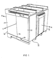
- a molded plastic housing 10 according to FIG. 1 has housing parts 12 and 14. Both housing parts 12 and 14 are formed by a fastener, z. B. screws, which are arranged in openings 18 of the housing part 12. Only one of the openings 18 is visible in FIG. 1, while a further opening 18 is arranged on the opposite side of the housing 10. The threaded part of the screws, not shown, extends into suitable threaded openings of the housing part 14. In this way, the housing parts 12 and 14 are held together against forces which act in the direction of arrows A and B in FIG. 1.
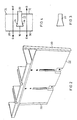
- the partition wall 22 has end webs 20.
- the profile of the end webs 20 can be seen in FIG. 3. Thereafter, an essentially dovetail-shaped section adjoins a parallel-walled section.
- FIG. 4 The interaction of the end webs 20 with the side walls 28 and 30 is shown in FIG. 4.
- the side walls 28 and 30 are provided in the region of the parting line 16 with recesses 24 and 26, respectively, which are adapted to the shape of the end web 20 shown in FIG.
- the side walls 28 and 30 overlap the end webs 20 in such a way that a positive connection is established and a mutual displacement of the side walls 28 and 30 at the parting line 16 is excluded.
- This is indicated by the double arrow pointing in the directions F and G in the region of the side wall 28 and the double arrow pointing in the directions D and E in the region of the side wall 30.
- the partition wall 22 with the end webs 20 acts as an additional stiffening of the side walls 28 and 30, since it can absorb tensile forces and therefore relieves the side walls of bending forces.
- FIG. 5 the installation of the partition 22 in the housing 10 can be seen particularly clearly from FIG. 5, in which the molded-material housing 10 is shown cut away in a top view.
- the molded plastic housing 10 and the partition wall 22 are provided with partitions for dividing the housing into three chambers for the three poles of a circuit breaker.
- the partition 22 In the area of the side walls 28 and 30 engages the partition 22 with its end webs 20 in the recesses 24 and 26 on the parting line 16 between the housing parts 12 and 14.
- the partition 22 is able to absorb tensile forces resulting from the internal overpressure on the side walls 28 and 30 which occurs during switching.
- the end webs 20 have a dovetail-shaped profile.
- other cross-sectional shapes are also suitable which, due to an undercut, have the same effect as a reinforcing part, e.g. B. a circular cross-section, hammer head cross-section or similar shapes.
Abstract
Ein isolierendes Formstoffgehäuse (10) eines Niederspannungs-Leistungsschalters weist zwei Gehäuseteile (12,14) auf, die entlang einer Teilfuge (16) zusammengefügt sind. Gegen die starken Beanspruchungen aufgrund eines beim Schalten auftretenden inneren Überdruckes ist das Formstoffgehäuse (10) durch eine Trennwand (22) verstärkt, die zwischen die Gehäuseteile (12,14) entlang der Teilfuge (16) eingefügt ist. Die Trennwand besitzt Endstege (20) mit einem hinterschnittenen, insbesondere schwalbenschwanzförmigen Profil, das in entsprechenden Ausnehmungen (24,26) in den Berührungsflächen der Gehäuseteile (12,14) aufgenommen ist. Dadurch kann die Trennwand (22) Zugkräfte aufnehmen. Ferner wird eine Relativbewegung zwischen den Seitenwänden (28,30) der Gehäuseteile (12,14) verhindert.An insulating molded-plastic housing (10) of a low-voltage circuit breaker has two housing parts (12, 14), which are joined together along a joint (16). The molding housing (10) is reinforced by a partition (22), which is inserted between the housing parts (12, 14) along the parting line (16) against the heavy stresses due to an internal excess pressure occurring during switching. The partition has end webs (20) with an undercut, in particular dovetail-shaped profile, which is received in corresponding recesses (24, 26) in the contact surfaces of the housing parts (12, 14). This allows the partition (22) to absorb tensile forces. A relative movement between the side walls (28, 30) of the housing parts (12, 14) is also prevented.
Description
Die Erfindung betrifft ein isolierendes Formstoffgehäuse eines Niederspannungs-Leistungsschalters mit zwei entlang einer Teilfuge aneinanderliegend verbundenen Gehäuseteilen sowie mit einem zur Verstärkung des Formstoffgehäuses gegenüber einem im Inneren wirkenden Überdruck dienenden, quer zu der Teilfuge angeordneten Wandteil. Ein Formstoffgehäuse dieser Art ist beispielsweise durch die DE-B-28 02 553 bekanntgeworden.The invention relates to an insulating molded-plastic housing of a low-voltage circuit breaker with two housing parts which are connected to one another along a part joint and with a wall part which is arranged transversely to the partial joint and serves to reinforce the molded-material housing against an overpressure acting on the inside. A molding material housing of this type has become known, for example, from DE-B-28 02 553.
Bei der Unterbrechung eines Stromkreises kann das Gehäuse eines Leistungsschalters extrem hohen Kräften ausgesetzt sein, die durch einen hohen Gasdruck in dem Gehäuse hervorgerufen werden. Dieser beruht auf den explosionsartig an den sich öffnenden Schaltkontakten entstehenden Lichtbögen in den Schaltkammern des Leistungsschalters. Die Geschwindigkeit des Druckanstieges ist dabei umso heftiger, je kleiner die Schaltkammern im Verhältnis zu dem geforderten Schaltvermögen sind. Daher unterliegen insbesondere die Formstoffgehäuse von Leistungsschaltern kompakter Bauart (MCCB = Molded Case Circuit Breaker und ICCB = Insulated Case Circuit Breaker) außerordentlichen Beanspruchungen beim Abschalten von Kurzschlußströmen. Das Gehäuse nach der erwähnten DE-B-28 02 553 ist dabei zur Vermeidung einer Beschädigung durch inneren Überdruck aufgrund von Schaltlichtbögen derart gestaltet, daß die Außenwände des Oberteiles des Gehäuses die Außenwände des Unterteiles übergreifen. Man erreicht dadurch, daß die von dem Gasdruck auf die Außenwände des Unterteiles ausgeübten Spreizkräfte zum Teil in die Außenwände des Oberteiles übergeleitet werden. Bei gleicher Druckbeanspruchung kann daher für die Außenwände des Unterteiles eine geringere Materialdicke gewählt werden. Der zur Verstärkung dienende Wandteil befindet sich dabei in dem Oberteil des Gehäuses und ist einstückig an dessen Seitenwände angeformt.When a circuit is interrupted, the housing of a circuit breaker can be subjected to extremely high forces which are caused by a high gas pressure in the housing. This is based on the arcing in the switching chambers of the circuit breaker, which arises explosively at the opening switching contacts. The speed of the pressure increase is all the more violent, the smaller the switching chambers are in relation to the required switching capacity. Therefore, the molded plastic housings of circuit breakers of compact design (MCCB = Molded Case Circuit Breaker and ICCB = Insulated Case Circuit Breaker) are subject to extraordinary stresses when short-circuit currents are switched off. The housing according to the mentioned DE-B-28 02 553 is designed to avoid damage due to internal overpressure due to switching arcs in such a way that the outer walls of the upper part of the housing overlap the outer walls of the lower part. It is thereby achieved that the spreading forces exerted by the gas pressure on the outer walls of the lower part are partially transferred into the outer walls of the upper part. With the same pressure load, a smaller material thickness can therefore be selected for the outer walls of the lower part. The wall part used for reinforcement is located in the upper part of the housing and is integrally formed on the side walls.
Der Erfindung liegt ausgehend hiervon die Aufgabe zugrunde, die Abstützung der Seitenwände der beiden Gehäuseteile zu verbessern und einen Gehäuseaufbau zu schaffen, der insbesondere für Niederspannungs-Leistungsschalter für den höheren Bereich von Nennströmen und Schaltleistungen geeignet ist.Proceeding from this, the object of the invention is to improve the support of the side walls of the two housing parts and to provide a housing structure which is particularly suitable for low-voltage circuit breakers for the higher range of nominal currents and switching powers.
Diese Aufgabe wird gemäß der Erfindung dadurch gelöst, daß der Wandteil zwischen die Gehäuseteile eingefügt ist und hierzu an gegenüberliegenden Seiten Endstege mit einem hinterschnittenen Profil aufweist und daß die Gehäuseteile im Bereich der Teilfuge je eine dem hinterschnittenen Profil angepaßte Nut aufweisen, derart, daß die Nuten die Endstege des Wandteiles formschlüssig übergreifen. In dieser Anordnung ist das Wandteil an der Aufnahme der Spreizkräfte im Bereich der Seitenwände beider Gehäuseteile direkt beteiligt. Durch die hinterschnittene Gestaltung im Bereich der Teilfuge wird ferner erreicht, daß sich die Seitenwände im Bereich der Teilfuge nicht gegeneinander verschieben können und somit ein Gasaustritt an dieser Stelle unterbleibt.This object is achieved according to the invention in that the wall part is inserted between the housing parts and for this purpose has end webs with an undercut profile on opposite sides and that the housing parts in the region of the joint each have a groove adapted to the undercut profile, such that the grooves overlap the end webs of the wall part in a form-fitting manner. In this arrangement, the wall part is directly involved in absorbing the expansion forces in the area of the side walls of both housing parts. The undercut design in the area of the parting joint also ensures that the side walls in the area of the parting joint cannot move against one another and thus there is no gas escape at this point.
Die Nuten der Endflächen der Gehäuseteile können gegenüber der Außenkante des Gehäuses zurückgesetzt angeordnet sein. Hierdurch entsteht eine labyrinthartig abgewinkelte Berührungsfläche zwischen den Seitenwänden und dem verstärkenden Wandteil. Damit wird ein für die elektrische Isolation vorteilhafter Kriechweg geschaffen und der Widerstand gegen den Durchtritt von Schaltgasen vergrößert.The grooves of the end faces of the housing parts can be arranged set back from the outer edge of the housing. This creates a labyrinth-like angled contact surface between the side walls and the reinforcing wall part. This creates a crawl path that is advantageous for electrical insulation and increases the resistance to the passage of switching gases.
Es erweist sich als vorteilhaft, den Wandteil als Trennwand zur Unterteilung des Formstoffgehäuses auszubilden. Die Funktion der Abstützung der Seitenwände des Formstoffgehäuses läßt sich auf diese Weise vorteilhaft mit einer inneren Unterteilung des Formstoffgehäuses in unterschiedliche Funktionsräume verbinden.It proves to be advantageous to design the wall part as a partition for dividing the molding material housing. In this way, the function of supporting the side walls of the molding material housing can advantageously be combined with an internal subdivision of the molding material housing into different functional spaces.
Die Erfindung wird im folgenden anhand des in den Figuren dargestellten Ausführungsbeispieles näher erläutert.
- Die Figur 1 zeigt eine perspektivische Ansicht des Formstoffgehäuses eines Niederspannungs-Leistungsschalters.
- Die Figur 2 ist eine perspektivische Ansicht einer zugleich der Verstärkung des in Figur 1 gezeigten Gehäuses dienenden Trennwand.
- In der Figur 3 ist ein verstärkendes Wandteil in einer Stirnansicht gezeigt.
- Die Figur 4 zeigt einen Ausschnitt aus dem Bereich von Seitenwänden des Formstoffgehäuses gemäß der Figur 1 mit einem dazwischen eingefügten verstärkenden Wandteil.
- Die Figur 5 ist eine Draufsicht auf die beiden Gehäuseteile eines Formstoffgehäuses mit einer dazwischen eingefügten Trennwand.
- FIG. 1 shows a perspective view of the molded material housing of a low-voltage circuit breaker.
- FIG. 2 is a perspective view of a partition wall which at the same time serves to reinforce the housing shown in FIG. 1.
- A reinforcing wall part is shown in an end view in FIG.
- FIG. 4 shows a section from the area of the side walls of the molding material housing according to FIG. 1 with a reinforcing wall part inserted between them.
- FIG. 5 is a top view of the two housing parts of a molding material housing with a partition wall inserted between them.
Ein Formstoffgehäuse 10 gemäß der Figur 1 weist Gehäuseteile 12 und 14 auf. Beide Gehäuseteile 12 und 14 sind unter Bildung einer Teilfuge 16 durch Befestigungsmittel, z. B. Schrauben, verbunden, die in Öffnungen 18 des Gehäuseteiles 12 angeordnet sind. In der Figur 1 ist nur eine der Öffnungen 18 sichtbar, während eine weitere Öffnung 18 auf der gegenüberliegenden Seite des Gehäuses 10 angeordnet ist. Der Gewindeteil der nicht gezeigten Schrauben erstreckt sich dabei in geeignete Gewindeöffnungen des Gehäuseteiles 14. Auf diese Weise werden die Gehäuseteile 12 und 14 gegenüber Kräften zusammengehalten, die in Richtung der Pfeile A und B in Figur 1 wirken.A molded
Zusätzlich zu den Kräften in der Richtung der Pfeile A und B treten jedoch auch aufgrund eines inneren Überdruckes infolge der Schaltvorgänge Kräfte in Richtung des Pfeiles C auf. Diese sind bestrebt, die Seitenwände 28 und 30 der Gehäuseteile 12 und 14 aufzuwölben. Zu einer starken Beanspruchung kommt es dabei insbesondere im Bereich der Teilfuge 16. Um die Beanspruchung der Seitenwände 28 und 30 in diesem Bereich zu verringern, ist zwischen die Gehäuseteile 12 und 14 eine Trennwand 22 eingefügt, die sich über die Breite des Formstoffgehäuses erstreckt (Fig. 5).In addition to the forces in the direction of arrows A and B, however, forces in the direction of arrow C also occur due to an internal overpressure as a result of the switching operations. These strive to bulge the
Wie der Figur 2 zu entnehmen ist, weist die Trennwand 22 Endstege 20 auf. Das Profil der Endstege 20 ist der Figur 3 zu entnehmen. Danach schließt sich an einen parallelwandigen Abschnitt ein im wesentlichen schwalbenschwanzförmiger Abschnitt an.As can be seen from FIG. 2, the
Das Zusammenwirken der Endstege 20 mit den Seitenwänden 28 und 30 ist in der Figur 4 dargestellt. Wie man erkennt, sind die Seitenwände 28 und 30 im Bereich der Teilfuge 16 mit Ausnehmungen 24 bzw. 26 versehen, die an die Gestalt des in der Figur 3 gezeigten Endsteges 20 angepaßt sind. Auf diese Weise übergreifen die Seitenwände 28 und 30 die Endstege 20 derart, daß eine formschlüssige Verbindung zustande kommt und eine gegenseitige Verschiebung der Seitenwände 28 und 30 an der Teilfuge 16 ausgeschlossen ist. Dies ist durch den in die Richtungen F und G weisenden Doppelpfeil im Bereich der Seitenwand 28 und den in die Richtungen D und E weisenden Doppelpfeil im Bereich der Seitenwand 30 angedeutet. Zugleich wirkt die Trennwand 22 mit den Endstegen 20 als zusätzliche Versteifung der Seitenwände 28 und 30, da sie Zugkräfte aufzunehmen vermag und daher die Seitenwände von Biegekräften entlastet.The interaction of the
Der Einbau der Trennwand 22 in das Gehäuse 10 ist besonders anschaulich der Figur 5 zu entnehmen, in der das Formstoffgehäuse 10 aufgeschnitten in der Draufsicht gezeigt ist. Das Formstoffgehäuse 10 und die Trennwand 22 sind mit Zwischenwänden zur Unterteilung des Gehäuses in drei Kammern für die drei Pole eines Leistungsschalters versehen. Im Bereich der Seitenwände 28 und 30 greift die Trennwand 22 mit ihren Endstegen 20 in die Ausnehmungen 24 und 26 an der Teilfuge 16 zwischen den Gehäuseteilen 12 und 14 ein. Hierdurch vermag die Trennwand 22 Zugkräfte aufzunehmen, die von dem beim Schalten auftretenden inneren Überdruck auf die Seitenwände 28 und 30 herrühren.The installation of the
In dem vorstehend beschriebenen Ausführungsbeispiel weisen die Endstege 20 ein schwalbenschwanzförmiges Profil auf. Es sind jedoch auch andere Querschnittsformen geeignet, die aufgrund einer Hinterschneidung sinngemäß die gleiche Wirkung als Verstärkungsteil ausüben, z. B. ein kreisförmiger Querschnitt, Hammerkopfquerschnitt oder ähnliche Formen.In the exemplary embodiment described above, the
Claims (4)
dadurch gekennzeichnet, daß der Wandteil (22) zwischen die Gehäuseteile (12,14) eingefügt ist und hierzu an gegenüberliegenden Seiten Endstege (20) mit einem hinterschnittenen Profil aufweist und daß die Gehäuseteile (12,14) im Bereich der Teilfuge (16) je eine dem hinterschnittenen Profil angepaßte Ausnehmung (24,26) aufweisen, derart, daß die Ausnehmungen (24,26) die Endstege (20) des Wandteiles (22) formschlüssig übergreifen.1. Insulating molded-plastic housing (10) of a low-voltage circuit breaker with two housing parts (12, 14) connected to one another along a parting joint (16) and with one that serves to reinforce the molded part housing (10) against an overpressure acting on the inside and transversely to the parting line ( 16) arranged wall part (22),
characterized in that the wall part (22) is inserted between the housing parts (12, 14) and for this purpose has end webs (20) with an undercut profile on opposite sides and in that the housing parts (12, 14) in the region of the parting line (16) each have a recess (24, 26) matched to the undercut profile, such that the recesses (24, 26) positively engage over the end webs (20) of the wall part (22).
dadurch gekennzeichnet, daß die Ausnehmungen (24,26) der Endflächen der Gehäuseteile (12,14) gegenüber der Außenkante des Gehäuses (10) zurückgesetzt angeordnet sind.2. molding material housing according to claim 1,
characterized in that the recesses (24, 26) of the end faces of the housing parts (12, 14) are arranged recessed with respect to the outer edge of the housing (10).
dadurch gekennzeichnet, daß der Wandteil als Trennwand (22) zur Unterteilung des Formstoffgehäuses (10) ausgebildet ist.3. molding material housing according to claim 1,
characterized in that the wall part is designed as a dividing wall (22) for dividing the molding material housing (10).
dadurch gekennzeichnet, daß das Profil der Endstege (20) schwalbenschwanzförmig ist.4. molding material housing according to claim 1,
characterized in that the profile of the end webs (20) is dovetail-shaped.
Applications Claiming Priority (2)
| Application Number | Priority Date | Filing Date | Title |
|---|---|---|---|
| US246470 | 1988-09-19 | ||
| US07/246,470 US4899253A (en) | 1988-09-19 | 1988-09-19 | Molded case circuit breaker housing reinforcement |
Publications (3)
| Publication Number | Publication Date |
|---|---|
| EP0360366A2 true EP0360366A2 (en) | 1990-03-28 |
| EP0360366A3 EP0360366A3 (en) | 1991-11-06 |
| EP0360366B1 EP0360366B1 (en) | 1994-11-30 |
Family
ID=22930815
Family Applications (1)
| Application Number | Title | Priority Date | Filing Date |
|---|---|---|---|
| EP89250035A Expired - Lifetime EP0360366B1 (en) | 1988-09-19 | 1989-09-13 | Moulded case for a low tension electrical power circuit breaker with reinforcement against overpressure |
Country Status (6)
| Country | Link |
|---|---|
| US (1) | US4899253A (en) |
| EP (1) | EP0360366B1 (en) |
| JP (1) | JPH02197022A (en) |
| CA (1) | CA1331775C (en) |
| DE (1) | DE58908683D1 (en) |
| ES (1) | ES2064429T3 (en) |
Families Citing this family (6)
| Publication number | Priority date | Publication date | Assignee | Title |
|---|---|---|---|---|
| US5189596A (en) * | 1991-12-20 | 1993-02-23 | Westinghouse Electric Corp. | Transition for electrical apparatus |
| US6005207A (en) * | 1997-09-23 | 1999-12-21 | Siemens Energy & Automation, Inc. | Multi-part circuit breaker housing |
| US8944070B2 (en) * | 1999-04-07 | 2015-02-03 | Intuitive Surgical Operations, Inc. | Non-force reflecting method for providing tool force information to a user of a telesurgical system |
| DE19958945A1 (en) * | 1999-11-26 | 2001-05-31 | Siemens Ag | Electrical switching device, such as low voltage (LV) circuit-breaker, with multi-part housing |
| DE10323094B3 (en) * | 2003-05-16 | 2004-08-12 | Siemens Ag | Electrical power switch has switch shaft supported by bearings provided by one housing shell with fixings between housing shells provided by shaft bearing and second housing shell |
| US20230377822A1 (en) * | 2022-05-20 | 2023-11-23 | Rockwell Automation Technologies, Inc. | Circuit breaker housing with two-stage structure |
Citations (3)
| Publication number | Priority date | Publication date | Assignee | Title |
|---|---|---|---|---|
| FR2309032A1 (en) * | 1975-04-21 | 1976-11-19 | Mang Ets Gerard | Compact, modular electric circuit breaker - has electromagnet and flat sub-assembly with moving and fixed contacts |
| EP0003736A1 (en) * | 1978-01-19 | 1979-09-05 | Siemens Aktiengesellschaft | Low-tension power circuit-breaker with a split insulant housing |
| EP0028013A1 (en) * | 1979-10-27 | 1981-05-06 | Fuji Electric Co. Ltd. | Power circuit breaker provided with a casing |
Family Cites Families (5)
| Publication number | Priority date | Publication date | Assignee | Title |
|---|---|---|---|---|
| US3422235A (en) * | 1966-01-28 | 1969-01-14 | Heinemann Electric Co | Arcing grid case support means |
| US3329793A (en) * | 1966-01-28 | 1967-07-04 | Heinemann Electric Co | Circuit breaker case |
| US4389555A (en) * | 1982-04-05 | 1983-06-21 | Heinemann Electric Company | Circuit breaker with increased electrical spacing |
| US4598186A (en) * | 1983-05-09 | 1986-07-01 | Square D Company | Vent arrangement for high amperage molded case circuit breaker |
| US4524339A (en) * | 1983-05-09 | 1985-06-18 | Square D Company | Contact control arrangement for high amperage molded case circuit breaker |
-
1988
- 1988-09-19 US US07/246,470 patent/US4899253A/en not_active Expired - Lifetime
-
1989
- 1989-09-13 JP JP1239744A patent/JPH02197022A/en active Pending
- 1989-09-13 ES ES89250035T patent/ES2064429T3/en not_active Expired - Lifetime
- 1989-09-13 DE DE58908683T patent/DE58908683D1/en not_active Expired - Fee Related
- 1989-09-13 EP EP89250035A patent/EP0360366B1/en not_active Expired - Lifetime
- 1989-09-15 CA CA000611594A patent/CA1331775C/en not_active Expired - Fee Related
Patent Citations (3)
| Publication number | Priority date | Publication date | Assignee | Title |
|---|---|---|---|---|
| FR2309032A1 (en) * | 1975-04-21 | 1976-11-19 | Mang Ets Gerard | Compact, modular electric circuit breaker - has electromagnet and flat sub-assembly with moving and fixed contacts |
| EP0003736A1 (en) * | 1978-01-19 | 1979-09-05 | Siemens Aktiengesellschaft | Low-tension power circuit-breaker with a split insulant housing |
| EP0028013A1 (en) * | 1979-10-27 | 1981-05-06 | Fuji Electric Co. Ltd. | Power circuit breaker provided with a casing |
Also Published As
| Publication number | Publication date |
|---|---|
| CA1331775C (en) | 1994-08-30 |
| EP0360366B1 (en) | 1994-11-30 |
| DE58908683D1 (en) | 1995-01-12 |
| US4899253A (en) | 1990-02-06 |
| EP0360366A3 (en) | 1991-11-06 |
| JPH02197022A (en) | 1990-08-03 |
| ES2064429T3 (en) | 1995-02-01 |
Similar Documents
| Publication | Publication Date | Title |
|---|---|---|
| EP0107611A1 (en) | Contact disconnecting device with bridging contact blades for pull-out switch-gears | |
| DE1590733A1 (en) | Electric circuit breaker | |
| EP0898779B1 (en) | Circuit breaker for low tension with connecting bars | |
| EP0360366B1 (en) | Moulded case for a low tension electrical power circuit breaker with reinforcement against overpressure | |
| EP0727805B1 (en) | Contact lever unit for low voltage circuit breaker | |
| DE3101532C2 (en) | Plug-in base for low-voltage circuit breakers | |
| DE10312820B4 (en) | Arc quenching plate assembly for an electrical switch, in particular an electrical circuit breaker | |
| EP0180537A2 (en) | Circuit breaker of the MCCB-type with two case parts | |
| EP0223732A1 (en) | Multipole low-voltage power circuit breaker with current bars | |
| EP0000711A1 (en) | Contactor with readily accessible wire connecting terminals disposed at different levels | |
| EP0916148A1 (en) | Switching chamber housing for a power switch and housing modules for producing such a switching chamber housing | |
| EP1297547B1 (en) | Connecting bars for electrical devices and apparatus for different nominal currents having a cavity | |
| EP1065683B1 (en) | Circuit breaker with terminals for different rated currents | |
| DE19939710A1 (en) | Connection rails for electrical devices and apparatus for various nominal currents | |
| EP1374264B1 (en) | Switching contact arrangement for a power switch | |
| DE2543959A1 (en) | Fuse load switch contact system on busbars - uses adaptor consisting of insulating plate with contacts | |
| EP0436578B1 (en) | Container for a gas-insulated medium-tension switch | |
| EP0003736A1 (en) | Low-tension power circuit-breaker with a split insulant housing | |
| DE69834897T2 (en) | Confusion protection arrangement for electrical switching devices, in particular for circuit breakers and residual current circuit breakers | |
| EP1267464B1 (en) | Insulator for electrical bus system, and insulating system making use of such insulators | |
| DE3735191C2 (en) | ||
| DE3931810A1 (en) | MOLDED HOUSING FOR CURRENT LIMIT SWITCHES | |
| EP0340700B1 (en) | Casing for a series-switching apparatus | |
| DE759073C (en) | Fuse with contact blades | |
| DE19653300A1 (en) | Housing for an electrical installation device, in particular for a circuit breaker or residual current circuit breaker or the like |
Legal Events
| Date | Code | Title | Description |
|---|---|---|---|
| PUAI | Public reference made under article 153(3) epc to a published international application that has entered the european phase |
Free format text: ORIGINAL CODE: 0009012 |
|
| AK | Designated contracting states |
Kind code of ref document: A2 Designated state(s): DE ES FR GB IT |
|
| 17P | Request for examination filed |
Effective date: 19901220 |
|
| PUAL | Search report despatched |
Free format text: ORIGINAL CODE: 0009013 |
|
| AK | Designated contracting states |
Kind code of ref document: A3 Designated state(s): DE ES FR GB IT |
|
| 17Q | First examination report despatched |
Effective date: 19940203 |
|
| GRAA | (expected) grant |
Free format text: ORIGINAL CODE: 0009210 |
|
| STAA | Information on the status of an ep patent application or granted ep patent |
Free format text: STATUS: THE PATENT HAS BEEN GRANTED |
|
| AK | Designated contracting states |
Kind code of ref document: B1 Designated state(s): DE ES FR GB IT |
|
| REF | Corresponds to: |
Ref document number: 58908683 Country of ref document: DE Date of ref document: 19950112 |
|
| REG | Reference to a national code |
Ref country code: ES Ref legal event code: FG2A Ref document number: 2064429 Country of ref document: ES Kind code of ref document: T3 |
|
| ITF | It: translation for a ep patent filed |
Owner name: STUDIO JAUMANN |
|
| ET | Fr: translation filed | ||
| GBT | Gb: translation of ep patent filed (gb section 77(6)(a)/1977) |
Effective date: 19950210 |
|
| PLBE | No opposition filed within time limit |
Free format text: ORIGINAL CODE: 0009261 |
|
| 26N | No opposition filed | ||
| REG | Reference to a national code |
Ref country code: GB Ref legal event code: IF02 |
|
| PGFP | Annual fee paid to national office [announced via postgrant information from national office to epo] |
Ref country code: GB Payment date: 20030904 Year of fee payment: 15 |
|
| PGFP | Annual fee paid to national office [announced via postgrant information from national office to epo] |
Ref country code: ES Payment date: 20030912 Year of fee payment: 15 |
|
| PGFP | Annual fee paid to national office [announced via postgrant information from national office to epo] |
Ref country code: FR Payment date: 20030930 Year of fee payment: 15 |
|
| PGFP | Annual fee paid to national office [announced via postgrant information from national office to epo] |
Ref country code: DE Payment date: 20031117 Year of fee payment: 15 |
|
| PG25 | Lapsed in a contracting state [announced via postgrant information from national office to epo] |
Ref country code: GB Free format text: LAPSE BECAUSE OF NON-PAYMENT OF DUE FEES Effective date: 20040913 |
|
| PG25 | Lapsed in a contracting state [announced via postgrant information from national office to epo] |
Ref country code: ES Free format text: LAPSE BECAUSE OF NON-PAYMENT OF DUE FEES Effective date: 20040914 |
|
| PG25 | Lapsed in a contracting state [announced via postgrant information from national office to epo] |
Ref country code: DE Free format text: LAPSE BECAUSE OF NON-PAYMENT OF DUE FEES Effective date: 20050401 |
|
| GBPC | Gb: european patent ceased through non-payment of renewal fee |
Effective date: 20040913 |
|
| PG25 | Lapsed in a contracting state [announced via postgrant information from national office to epo] |
Ref country code: FR Free format text: LAPSE BECAUSE OF NON-PAYMENT OF DUE FEES Effective date: 20050531 |
|
| REG | Reference to a national code |
Ref country code: FR Ref legal event code: ST |
|
| PG25 | Lapsed in a contracting state [announced via postgrant information from national office to epo] |
Ref country code: IT Free format text: LAPSE BECAUSE OF NON-PAYMENT OF DUE FEES;WARNING: LAPSES OF ITALIAN PATENTS WITH EFFECTIVE DATE BEFORE 2007 MAY HAVE OCCURRED AT ANY TIME BEFORE 2007. THE CORRECT EFFECTIVE DATE MAY BE DIFFERENT FROM THE ONE RECORDED. Effective date: 20050913 |
|
| REG | Reference to a national code |
Ref country code: ES Ref legal event code: FD2A Effective date: 20040914 |