EP0360028A1 - Method of joining heating pipes - Google Patents
Method of joining heating pipes Download PDFInfo
- Publication number
- EP0360028A1 EP0360028A1 EP89115686A EP89115686A EP0360028A1 EP 0360028 A1 EP0360028 A1 EP 0360028A1 EP 89115686 A EP89115686 A EP 89115686A EP 89115686 A EP89115686 A EP 89115686A EP 0360028 A1 EP0360028 A1 EP 0360028A1
- Authority
- EP
- European Patent Office
- Prior art keywords
- foam
- bridge
- pipes
- pipe
- jacket
- Prior art date
- Legal status (The legal status is an assumption and is not a legal conclusion. Google has not performed a legal analysis and makes no representation as to the accuracy of the status listed.)
- Granted
Links
Images
Classifications
-
- F—MECHANICAL ENGINEERING; LIGHTING; HEATING; WEAPONS; BLASTING
- F16—ENGINEERING ELEMENTS AND UNITS; GENERAL MEASURES FOR PRODUCING AND MAINTAINING EFFECTIVE FUNCTIONING OF MACHINES OR INSTALLATIONS; THERMAL INSULATION IN GENERAL
- F16L—PIPES; JOINTS OR FITTINGS FOR PIPES; SUPPORTS FOR PIPES, CABLES OR PROTECTIVE TUBING; MEANS FOR THERMAL INSULATION IN GENERAL
- F16L59/00—Thermal insulation in general
- F16L59/14—Arrangements for the insulation of pipes or pipe systems
- F16L59/16—Arrangements specially adapted to local requirements at flanges, junctions, valves or the like
- F16L59/18—Arrangements specially adapted to local requirements at flanges, junctions, valves or the like adapted for joints
- F16L59/20—Arrangements specially adapted to local requirements at flanges, junctions, valves or the like adapted for joints for non-disconnectable joints
Definitions
- the invention relates to a method for connecting district heating pipes, which consist of a medium pipe made of steel, a jacket pipe made of plastic and a foam filling in between, the medium pipes are exposed and welded at the ends to be connected and then the gaps between the jacket pipes and the foam fillings are closed by flush insertion of a jacket pipe intermediate piece and foaming of the existing space, the intermediate piece being connected to the two adjacent jacket pipes by, in particular welded, seams and being closed at a longitudinal diameter and for which a support from the inside is provided, which is provided with is foamed.
- the intermediate piece required a complicated support from the medium pipe, which was subsequently foamed in, because otherwise the heating would cause the plastic in the vicinity of the weld seam to shrink and thus lead to a deformation of the intermediate piece; it sinks there.
- the invention has for its object to provide a simple suitable support for the intermediate piece on the longitudinal average.
- this purpose is achieved in such a way that, as the support, a bridge is placed over the gap between the foam fillings and is supported on the previously exposed, both ends of the foam fillings.
- the support of the intermediate piece is decidedly simpler and more stable, although it requires these ends to be exposed.
- the U-profile is just as simple in structure as in its attachment, in which the thinner U-legs easily cut into the foam, and this attachment is then stable and, in contrast to the known support on the carrier pipe, secure against anything Slipping, both in the axial and in the circumferential direction.
- the two ends of the adjacent foam fillings are expediently removed a little before the bridge is placed on the circumference, so that the desired alignment of the top of the bridge with the underside of the casing pipes can be set up precisely.
- the cavity that is further created by the removal under the intermediate piece is also filled when foaming.
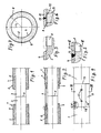
- Two district heating pipes 1 and 2 each consist of a medium pipe 3, a casing pipe 4 and a foam filling 5 between the medium pipe and casing pipe. At the ends of the district heating pipes 1 and 2, the medium pipe 3 protrudes freely so that it can be welded when the district heating pipe is laid.
- the weld seam in question is designated by 6.
- a bridge 8 is placed over the axial gap between the foam fillings 5 of the district heating pipes 1 and 2, which is still present in FIG. According to the drawing, see the difference between FIGS. 2 and 1, section 7 has been exposed at the construction site. It could also be provided at the factory, but the exposure only at the construction site has the advantage that the weaker foam is protected by the firmer jacket tube during transport and other movements of the district heating pipes.
- the bridge 8 consists, for example, of a U-section folded aluminum sheet and is so deeply pressed into the foam filling with the U-legs 9 that the top of the bridge lies flush with the outer circumference of the foam filling 5 and the inner circumference of the casing tube 4. Below this, a flat space 10 remains between the aluminum sheet and the peeled foam filling.
- the intermediate piece 11 is of the same material, same wall thick and the same diameter as the jacket tube 4, but cut parallel to the tube axis at one point on its wall.
- the longitudinal intersection 12 is welded in the same way as the joints between the intermediate piece 11 and the casing 4 of the two district heating pipes 1 and 2.
- a V-seam 13 at one of the two joints can be seen in FIG. 5, a V-seam 14 at the longitudinal intersection 12 in FIG. 7.
- the intermediate piece 11 is supported by the bridge 8 from the inside when welding the longitudinal average 12 to it.
- the cavity under the intermediate piece 11 is then foamed through a hole or a plurality of holes 15 in the intermediate piece 11 in a manner known per se.
- the bridge 8 is also foamed. 4, 5 and 7 show the stage after foaming. In Fig. 6 the intermediate piece is inserted, but not yet foamed.
Abstract
Description
Die Erfindung betrifft ein Verfahren zum Verbinden von Fernwärmeleitungsrohren, die aus einem Mediumrohr aus Stahl, einem Mantelrohr aus Kunststoff und einer Schaumstoffüllung dazwischen bestehen, wobei an den zu verbindenden Enden die Mediumrohre freiliegen und verschweißt werden und dann darüber die Lücken zwischen den Mantelrohren und den Schaumstoffüllungen geschlossen werden durch bündiges Einsetzen eines Mantelrohr-Zwischenstücks und Ausschäumen des vorhandenen Zwischenraumes, wobei das Zwischenstück durch, insbesondere geschweißte, Nähte mit den beiden angrenzenden Mantelrohren verbunden und an einem Längsdurchmesser geschlossen wird und an diesem dafür eine Abstützung von innen her vorgesehen ist, die mit eingeschäumt wird.The invention relates to a method for connecting district heating pipes, which consist of a medium pipe made of steel, a jacket pipe made of plastic and a foam filling in between, the medium pipes are exposed and welded at the ends to be connected and then the gaps between the jacket pipes and the foam fillings are closed by flush insertion of a jacket pipe intermediate piece and foaming of the existing space, the intermediate piece being connected to the two adjacent jacket pipes by, in particular welded, seams and being closed at a longitudinal diameter and for which a support from the inside is provided, which is provided with is foamed.
Üblich ist bisher kein bündiges Zwischenstück des Mantelrohres, sondern eine Muffe. Die Muffe wird vor dem Verschweißen der Mediumrohrenden auf eines der beiden Mantelrohrenden aufgeschoben und dann über die Lücke geschoben und mit beiden Mantelrohrenden dicht verbunden. Darauf wird der Zwischenraum ausgeschäumt.So far, it is not a flush intermediate piece of the casing tube, but a sleeve. Before the medium pipe ends are welded, the sleeve is pushed onto one of the two jacket pipe ends and then pushed over the gap and tightly connected to both jacket pipe ends. The space in between is then foamed.
Obwohl auf die Verbindung der Muffe mit den beiden Mantelrohrenden große Sorgfalt gelegt wird und mehrere Verbindungsarten entwickelt und angewandt wurden, entstehen an den Verbindungen häufig Undichtigkeiten.Although great care is taken to connect the sleeve to the two jacket pipe ends and several types of connection have been developed and used, leaks often occur at the connections.
In der Erwägung, daß hierzu Schubkräfte beitragen, die infolge Wärmeausdehnung von Abschnitten der Fernwärmeleitung an den radial in das Erdreich vorspringenden und damit stärker festgehaltenen Muffen entstehen, hat man in der eingangs genannten Weise versucht, die Lücke zwischen den beiden Mantelrohrenden durch ein bündig eingesetztes Zwischenstück zu schließen. Da dieses Zwischenstück gleichen Durchmesser wie das übrige Mantelrohr hat, läßt es sich nur mit einem Längsdurchschnitt und etwas aufgespreizt auf ein Mantelrohrende aufschieben, stattdessen aber auch an dem Längsdurchschnitt so weit auseinanderziehen, daß es mit diesem von der Seite her über das Mediumrohr gebracht werden kann. Der Längsdurchschnitt mußte dann ebenso verschweißt werden wie die beiden Stoßstellen mit den angrenzenden Mantelrohrenden. Anschließend konnte der Zwischenraum wieder in bekannter Weise ausgeschäumt werden.
An dem Längsdurchschnitt bedurfte das Zwischenstück allerdings einer, nachher mit eingeschäumten, komplizierten Abstützung vom Mediumrohr her, weil die Erhitzung sonst zu einem Schrumpfen des Kunststoffs in der Umgebung der Schweißnaht und damit zu einer Verformung des Zwischenstücks führt; es sinkt dort ein.Considering that shear forces contribute to this, which arise as a result of thermal expansion of sections of the district heating pipe at the sleeves projecting radially into the ground and thus more firmly held, attempts have been made in the manner mentioned at the beginning to bridge the gap between the two casing ends by a flush-fitted intermediate piece close. Since this intermediate piece has the same diameter as the rest of the casing pipe, it can only be pushed onto a casing pipe end with a longitudinal average and slightly spread apart, but instead also pulled apart so far at the longitudinal section that it can be brought from the side over the medium pipe . The longitudinal intersection then had to be welded as well as the two joints with the adjacent casing tube ends. Subsequently, the space in between could be foamed in a known manner.
At the longitudinal intersection, however, the intermediate piece required a complicated support from the medium pipe, which was subsequently foamed in, because otherwise the heating would cause the plastic in the vicinity of the weld seam to shrink and thus lead to a deformation of the intermediate piece; it sinks there.
Der Erfindung liegt die Aufgabe zugrunde, eine einfache geeignete Abstützung für das Zwischenstück an dem Längsdurchschnitt zu schaffen.The invention has for its object to provide a simple suitable support for the intermediate piece on the longitudinal average.
Gemäß der Erfindung wird dieser Zweck in der Weise erfüllt, daß als die Abstützung eine Brücke über die Lücke zwischen den Schaumstoffüllungen gelegt und auf den, vorher freigelegten, beiden Enden der Schaumstoffüllungen abgestützt wird.According to the invention, this purpose is achieved in such a way that, as the support, a bridge is placed over the gap between the foam fillings and is supported on the previously exposed, both ends of the foam fillings.
Die Abstützung des Zwischenstücks nicht wie bislang, vom Mediumrohr her, sondern über eine Brücke auf den Enden der Schaumstofffüllungen ist, obwohl sie das Freilegen dieser Enden verlangt, entschieden einfacher und stabiler.The support of the intermediate piece, not so far from the carrier pipe, but via a bridge on the ends of the foam fillings, is decidedly simpler and more stable, although it requires these ends to be exposed.
Beides ist sie in erhöhtem Maße, wenn nach einer Weiterbildung der Erfindung eine aus einem Blech, vorzugsweise Aluminiumblech, zu einem U-Profil gekantete Brücke verwendet wird, dessen Schenkel in die Schaumstoffüllungen eingedrückt werden.It is both to an increased degree if, according to a development of the invention, one made of sheet metal, preferably aluminum sheet, used to form a U-shaped bridge whose legs are pressed into the foam fillings.
Das U-Profil ist ebenso einfach im Aufbau wie in seiner Anbringung, bei der sich die dünneren U-Schenkel leicht in den Schaumstoff einschneiden, und diese Anbringung ist dann trotzdem stabil und, im Gegensatz zu der bekannten Abstützung auf dem Mediumrohr, sicher gegen jegliches Verrutschen, sowohl in Axialals auch in Umfangsrichtung.The U-profile is just as simple in structure as in its attachment, in which the thinner U-legs easily cut into the foam, and this attachment is then stable and, in contrast to the known support on the carrier pipe, secure against anything Slipping, both in the axial and in the circumferential direction.
Die beiden Enden der angrenzenden Schaumstoffüllungen werden zweckmäßigerweise vor dem Auflegen der Brücke am Umfang etwas abgetragen, damit die gewünschte Flucht der Oberseite der Brücke mit der Unterseite der Mantelrohre genau eingerichtet werden kann. Der durch das Abtragen unter dem Zwischenstück weiter entstehende Hohlraum wird beim Ausschäumen gleichfalls gefüllt.The two ends of the adjacent foam fillings are expediently removed a little before the bridge is placed on the circumference, so that the desired alignment of the top of the bridge with the underside of the casing pipes can be set up precisely. The cavity that is further created by the removal under the intermediate piece is also filled when foaming.
Die Zeichnung gibt ein Ausführungsbeispiel der Erfindung wieder.
- Fig. 1 zeigt eine Verbindungsstelle von zwei aneinandergesetzten, noch zu verbindenden Fernwärmeleitungsrohren im Längsschnitt der Fernwärmeleitungsrohre,
- Fig. 2 zeigt die Verbindungsstelle im gleichen Längsschnitt in einem Zwischenstadium,
- Fig. 3 zeigt in größerem Maßstab den in Fig. 2 umkreisten Ausschnitt,
- Fig. 4 zeigt die fertige Verbindungsstelle teils in Ansicht und teils im gleichen Längsschnitt,
- Fig. 5 zeigt den in Fig. 4 umkreisten Längsschnitt in größerem Maßstab,
- Fig. 6 zeigt einen Schnitt nach Linie VI-VI in Fig. 5, aber in noch nicht ganz fertigem Zustand der Verbindungsstelle und
- Fig. 7 zeigt in größerem Maßstab einen Schnitt nach Linie VII-VII in Fig. 4.
- 1 shows a connection point of two district heating pipes, which are placed next to one another and are yet to be connected, in the longitudinal section of the district heating pipes,
- 2 shows the connection point in the same longitudinal section in an intermediate stage,
- 3 shows on a larger scale the section encircled in FIG. 2,
- 4 shows the finished connection point partly in view and partly in the same longitudinal section,
- 5 shows the longitudinal section encircled in FIG. 4 on a larger scale,
- Fig. 6 shows a section along line VI-VI in Fig. 5, but in the not yet fully finished state of the junction and
- FIG. 7 shows a section along line VII-VII in FIG. 4 on a larger scale.
Zwei Fernwärmeleitungsrohre 1 und 2 bestehen jeweils aus einem Mediumrohr 3, einem Mantelrohr 4 und einer Schaumstoffüllung 5 zwischen Mediumrohr und Mantelrohr. An den Enden der Fernwärmeleitungsrohre 1 und 2 ragt das Mediumrohr 3 ein Stück frei heraus, um beim Verlegen der Fernwärmeleitung verschweißt werden zu können. Die betreffende Schweißnaht ist mit 6 bezeichnet.Two
Nach dem Verschweißen des Mediumsrohres wird über die in Fig. 1 noch vorhandene axiale Lücke zwischen den Schaumstoffüllungen 5 der Fernwärmeleitungsrohre 1 und 2 eine Brücke 8 gelegt und jeweils an den beiden Leitungsrohrenden auf einem freigelegten und etwas abgeschälten Abschnitt 7 der Schaumstofffüllung 5 abgestützt.
Nach der Zeichnung ist, siehe den Unterschied zwischen Fig. 2 und Fig. 1, der Abschnitt 7 an der Baustelle freigelegt worden. Er könnte auch schon werksseitig vorgesehen werden, doch hat das Freilegen erst an der Baustelle den Vorteil, daß der schwächere Schaumstoff durch das festere Mantelrohr beim Transport und sonstigen Bewegen der Fernwärmeleitungsrohre geschützt bleibt.After the medium pipe has been welded, a
According to the drawing, see the difference between FIGS. 2 and 1, section 7 has been exposed at the construction site. It could also be provided at the factory, but the exposure only at the construction site has the advantage that the weaker foam is protected by the firmer jacket tube during transport and other movements of the district heating pipes.
Die Brücke 8 besteht beispielsweise aus zu einem U-Profil gekantetem Aluminiumblech und ist mit den U-Schenkeln 9 in die Schaumstoffüllung so tief eingedrückt, daß die Oberseite der Brücke mit bündig mit dem Außenumfang der Schaumstoffüllung 5 und dem Innenumfang des Mantelrohres 4 liegt. Darunter bleibt zwischen dem Aluminiumblech und der abgeschälten Schaumstofffüllung ein flacher Zwischenraum 10.The
Daraufhin wird ein Zwischenstück 11 des Mantelrohres, das vorher beispielsweise auf das Fernwärmeleitungsrohr 2 aufgeschoben war, in die in Fig. 2 noch vorhandene axiale Lücke zwischen den Mantelrohren 2 geschoben und diese Lücke damit geschlossen.Thereupon, an
Das Zwischenstück 11 ist von gleichem Material, gleicher Wand dicke und gleichem Durchmesser wie das Mantelrohr 4, aber an einer Stelle seiner Wandung parallel zur Rohrachse durchgeschnitten. An dem, mit 12 bzeichneten, Längsdurchschnitt klafft es auseinander, wenn es auf das eine Fernwärmeleitungsrohr aufgeschoben ist oder, bei genügender Elastizität, soweit aufgespreizt wird, daß es in dem Stadium nach Fig. 2 von der Seite her über die Manschette gebracht werden kann.The
Der Längsdurchschnitt 12 wird in gleicher Weise verschweißt wie es die Stoßstellen zwischen dem Zwischenstück 11 und dem Mantelrohr 4 der beiden Fernwärmeleitungsrhre 1 und 2 werden. Eine V-Naht 13 an einer der beiden Stoßstellen ist in Fig. 5 zu erkennen, eine V-Naht 14 an dem Längsdurchschnitt 12 in Fig.7.The longitudinal intersection 12 is welded in the same way as the joints between the
Das Zwischenstück 11 ist beim Verschweißen des Längsdurchschnitts 12 an diesem von innen her durch die Brücke 8 unterstützt.The
Dann wird in an sich bekannter Weise durch ein Loch oder mehrere Löcher 15 in dem Zwischenstück 11 hindurch der Hohlraum unter dem Zwischenstück 11 ausgeschäumt. Die Brücke 8 wird mit eingeschäumt. Fig. 4;5 und 7 zeigen das Stadium nach dem Ausschäumen. In Fig. 6 ist das Zwischenstück eingesetzt, aber noch nicht ausgeschäumt.The cavity under the
Claims (3)
dadurch gekennzeichnet,
daß als die Abstützung eine Brücke (8) über die Lücke zwischen den Schaumstoffüllungen (5) gelegt und auf den, vorher freigelegten, beiden Enden (7) der Schaumstoffüllungen (5) abgestützt wird.1. A method for connecting district heating pipes (1; 2), which consist of a medium pipe (3) made of steel, a jacket pipe (4) made of plastic and a foam filling (5) in between, the medium pipes (3) being connected at the ends to be connected. are exposed and welded (6) and then the gaps between the casing pipes (4) and the foam fillings (5) are closed by flush insertion of a casing pipe intermediate piece (11) and foaming (14) of the existing intermediate space, the intermediate piece (11 ) by, in particular welded, seams (13) connected to the two adjacent casing tubes (4) and closed at a longitudinal intersection (12) and a support (8) is provided on the inside for this purpose, which is also foamed in,
characterized,
that as the support a bridge (8) is placed over the gap between the foam fillings (5) and is supported on the previously exposed, both ends (7) of the foam fillings (5).
dadurch gekennzeichnet,
daß die beiden Enden (7) der angrenzenden Schaumstoffüllungen (5) vor dem Auflegen der Brücke (8) am Umfang abgetragen worden sind.2. The method according to claim 1,
characterized,
that the two ends (7) of the adjacent foam fillings (5) have been removed on the circumference before the bridge (8) is placed on them.
dadurch gekennzeichnet,
daß eine Brücke (8) aus einem, vorzugsweise aus Blech gekanteten, U-Profil verwendet wird, dessen Schenkel (9) in die Schaumstoffüllungen (5) eingedrückt worden sind.3. The method according to claim 1 or 2,
characterized,
that a bridge (8) made of a U-profile, preferably folded from sheet metal, is used, the legs (9) of which have been pressed into the foam fillings (5).
Priority Applications (1)
| Application Number | Priority Date | Filing Date | Title |
|---|---|---|---|
| AT89115686T ATE76682T1 (en) | 1988-09-17 | 1989-08-25 | METHOD OF CONNECTING DISTRICT HEATING PIPES. |
Applications Claiming Priority (2)
| Application Number | Priority Date | Filing Date | Title |
|---|---|---|---|
| DE3831623 | 1988-09-17 | ||
| DE3831623A DE3831623A1 (en) | 1988-09-17 | 1988-09-17 | METHOD FOR CONNECTING REMOTE HEATING PIPES |
Publications (2)
| Publication Number | Publication Date |
|---|---|
| EP0360028A1 true EP0360028A1 (en) | 1990-03-28 |
| EP0360028B1 EP0360028B1 (en) | 1992-05-27 |
Family
ID=6363137
Family Applications (1)
| Application Number | Title | Priority Date | Filing Date |
|---|---|---|---|
| EP89115686A Expired - Lifetime EP0360028B1 (en) | 1988-09-17 | 1989-08-25 | Method of joining heating pipes |
Country Status (3)
| Country | Link |
|---|---|
| EP (1) | EP0360028B1 (en) |
| AT (1) | ATE76682T1 (en) |
| DE (2) | DE3831623A1 (en) |
Cited By (5)
| Publication number | Priority date | Publication date | Assignee | Title |
|---|---|---|---|---|
| WO1994029635A1 (en) * | 1993-06-15 | 1994-12-22 | Abb District Heating Technology A/S | A district heating pipe stretch and a method of establishing such a stretch |
| WO1998001697A1 (en) * | 1996-07-03 | 1998-01-15 | Bredero Price Coaters Limited | Field joint |
| WO2013110947A1 (en) * | 2012-01-25 | 2013-08-01 | Subsea 7 Limited | Connections for subsea pipe-in-pipe structures |
| RU2699152C2 (en) * | 2017-07-11 | 2019-09-03 | Общество с ограниченной ответственностью "СТЕКЛОНиТ Менеджмент" | Insulation system in road conditions of installation joints of adjacent pipelines with insulating coating |
| CN113210917A (en) * | 2021-05-19 | 2021-08-06 | 江苏安全技术职业学院 | Drum-type automatic welding machine |
Citations (3)
| Publication number | Priority date | Publication date | Assignee | Title |
|---|---|---|---|---|
| EP0098024A1 (en) * | 1982-06-29 | 1984-01-11 | i.c. Möller a/s | A method of joining prefabricated heat insulated pipes and a welding fitting therefor |
| FR2535570A1 (en) * | 1982-10-29 | 1984-05-04 | Kabelmetal Electro Gmbh | Electrical heating strip for producing a sleeve junction for thermally insulated tubular piping, and its method of manufacture. |
| EP0278050A1 (en) * | 1987-01-30 | 1988-08-17 | kabelmetal electro GmbH | Sleeve connection for thermally insulated pipes |
-
1988
- 1988-09-17 DE DE3831623A patent/DE3831623A1/en not_active Withdrawn
-
1989
- 1989-08-25 DE DE8989115686T patent/DE58901535D1/en not_active Expired - Lifetime
- 1989-08-25 EP EP89115686A patent/EP0360028B1/en not_active Expired - Lifetime
- 1989-08-25 AT AT89115686T patent/ATE76682T1/en not_active IP Right Cessation
Patent Citations (3)
| Publication number | Priority date | Publication date | Assignee | Title |
|---|---|---|---|---|
| EP0098024A1 (en) * | 1982-06-29 | 1984-01-11 | i.c. Möller a/s | A method of joining prefabricated heat insulated pipes and a welding fitting therefor |
| FR2535570A1 (en) * | 1982-10-29 | 1984-05-04 | Kabelmetal Electro Gmbh | Electrical heating strip for producing a sleeve junction for thermally insulated tubular piping, and its method of manufacture. |
| EP0278050A1 (en) * | 1987-01-30 | 1988-08-17 | kabelmetal electro GmbH | Sleeve connection for thermally insulated pipes |
Cited By (10)
| Publication number | Priority date | Publication date | Assignee | Title |
|---|---|---|---|---|
| WO1994029635A1 (en) * | 1993-06-15 | 1994-12-22 | Abb District Heating Technology A/S | A district heating pipe stretch and a method of establishing such a stretch |
| GB2294742A (en) * | 1993-06-15 | 1996-05-08 | Abb District Heating Managemen | A district heating pipe stretch and a method of establishing such a stretch |
| WO1998001697A1 (en) * | 1996-07-03 | 1998-01-15 | Bredero Price Coaters Limited | Field joint |
| US6264871B1 (en) | 1996-07-03 | 2001-07-24 | Bredero Price Coaters Ltd. | Field joint |
| WO2013110947A1 (en) * | 2012-01-25 | 2013-08-01 | Subsea 7 Limited | Connections for subsea pipe-in-pipe structures |
| GB2498740B (en) * | 2012-01-25 | 2014-09-10 | Subsea 7 Ltd | Connections for subsea pipe-in-pipe structures |
| US9857011B2 (en) | 2012-01-25 | 2018-01-02 | Subsea 7 Limited | Connections for subsea pipe-in-pipe structures |
| RU2699152C2 (en) * | 2017-07-11 | 2019-09-03 | Общество с ограниченной ответственностью "СТЕКЛОНиТ Менеджмент" | Insulation system in road conditions of installation joints of adjacent pipelines with insulating coating |
| CN113210917A (en) * | 2021-05-19 | 2021-08-06 | 江苏安全技术职业学院 | Drum-type automatic welding machine |
| CN113210917B (en) * | 2021-05-19 | 2022-11-25 | 江苏安全技术职业学院 | Drum-type automatic weld machine |
Also Published As
| Publication number | Publication date |
|---|---|
| DE3831623A1 (en) | 1990-03-22 |
| ATE76682T1 (en) | 1992-06-15 |
| EP0360028B1 (en) | 1992-05-27 |
| DE58901535D1 (en) | 1992-07-02 |
Similar Documents
| Publication | Publication Date | Title |
|---|---|---|
| DE2635126C3 (en) | Pressure medium-operated holding device | |
| DE2219196A1 (en) | Pipe coupling | |
| DE8213761U1 (en) | PIPE CONNECTION FOR PIPELINES FROM INSULATED DOUBLE PIPES | |
| DE3509217C2 (en) | Method of connecting a sleeve to a pipe of an underwater pipeline | |
| DE3427945A1 (en) | DEVICE FOR CONNECTING THE END OF PIPELINES | |
| EP0521822B1 (en) | Device for the connection of two jacket tubes | |
| DE3528061A1 (en) | TELESCOPIC CONNECTOR | |
| CH679240A5 (en) | ||
| DE8234897U1 (en) | LINE TUBE FOR A CHANNEL BASIC PIPE | |
| EP0360028A1 (en) | Method of joining heating pipes | |
| DE2002826A1 (en) | Coupling piece for pipes or hoses | |
| EP0009105B1 (en) | Plastic pipe | |
| DE19718790A1 (en) | Welded connection for plastic pipe used for burrowing into earth | |
| DE2646359B2 (en) | Pipe coupling for tensile M-connection of pipe ends | |
| DE2938006C2 (en) | Device for connecting two smooth pipe ends | |
| DE3315819A1 (en) | Pipeline for conveying, in particular, corrosive media, and a method for assembling and laying the pipeline | |
| DE2016440C3 (en) | Pipe connection | |
| DE2362926A1 (en) | PROCEDURE FOR CONNECTING PIPES AND SOCKET FOR CARRYING OUT THE PROCEDURE | |
| DE3534174A1 (en) | Jointing sleeve for tube ends | |
| DE3826078A1 (en) | Process for connecting district-heating pipes | |
| DE2352711C3 (en) | Clamping device for a hose-shaped elastic coupling piece | |
| EP0687849A1 (en) | Method of limiting fast crack propagation in plastic pipes and pipes obtained by such method | |
| DE4243353C2 (en) | Jacking pipe connection for underground shield jacking | |
| DE1525677C (en) | Pipe socket for connecting two pipes to one another | |
| DE8428374U1 (en) | PLASTIC PIPE TO RENOVATE PIPELINES |
Legal Events
| Date | Code | Title | Description |
|---|---|---|---|
| PUAI | Public reference made under article 153(3) epc to a published international application that has entered the european phase |
Free format text: ORIGINAL CODE: 0009012 |
|
| AK | Designated contracting states |
Kind code of ref document: A1 Designated state(s): AT BE CH DE FR IT LI NL |
|
| 17P | Request for examination filed |
Effective date: 19900816 |
|
| 17Q | First examination report despatched |
Effective date: 19910328 |
|
| GRAA | (expected) grant |
Free format text: ORIGINAL CODE: 0009210 |
|
| AK | Designated contracting states |
Kind code of ref document: B1 Designated state(s): AT BE CH DE FR IT LI NL |
|
| REF | Corresponds to: |
Ref document number: 76682 Country of ref document: AT Date of ref document: 19920615 Kind code of ref document: T |
|
| ITF | It: translation for a ep patent filed |
Owner name: STUDIO INGG. FISCHETTI & WEBER |
|
| REF | Corresponds to: |
Ref document number: 58901535 Country of ref document: DE Date of ref document: 19920702 |
|
| ET | Fr: translation filed | ||
| PLBE | No opposition filed within time limit |
Free format text: ORIGINAL CODE: 0009261 |
|
| STAA | Information on the status of an ep patent application or granted ep patent |
Free format text: STATUS: NO OPPOSITION FILED WITHIN TIME LIMIT |
|
| 26N | No opposition filed | ||
| PGFP | Annual fee paid to national office [announced via postgrant information from national office to epo] |
Ref country code: FR Payment date: 19940620 Year of fee payment: 6 |
|
| PGFP | Annual fee paid to national office [announced via postgrant information from national office to epo] |
Ref country code: CH Payment date: 19940728 Year of fee payment: 6 |
|
| PGFP | Annual fee paid to national office [announced via postgrant information from national office to epo] |
Ref country code: AT Payment date: 19940823 Year of fee payment: 6 |
|
| PGFP | Annual fee paid to national office [announced via postgrant information from national office to epo] |
Ref country code: BE Payment date: 19940902 Year of fee payment: 6 |
|
| PG25 | Lapsed in a contracting state [announced via postgrant information from national office to epo] |
Ref country code: AT Effective date: 19950825 |
|
| PG25 | Lapsed in a contracting state [announced via postgrant information from national office to epo] |
Ref country code: LI Effective date: 19950831 Ref country code: CH Effective date: 19950831 Ref country code: BE Effective date: 19950831 |
|
| BERE | Be: lapsed |
Owner name: DSD - DILLINGER STAHLBAU G.M.B.H. Effective date: 19950831 |
|
| REG | Reference to a national code |
Ref country code: CH Ref legal event code: PL |
|
| PG25 | Lapsed in a contracting state [announced via postgrant information from national office to epo] |
Ref country code: FR Effective date: 19960430 |
|
| REG | Reference to a national code |
Ref country code: FR Ref legal event code: ST |
|
| PGFP | Annual fee paid to national office [announced via postgrant information from national office to epo] |
Ref country code: NL Payment date: 19990823 Year of fee payment: 11 |
|
| PG25 | Lapsed in a contracting state [announced via postgrant information from national office to epo] |
Ref country code: NL Free format text: LAPSE BECAUSE OF NON-PAYMENT OF DUE FEES Effective date: 20010301 |
|
| NLV4 | Nl: lapsed or anulled due to non-payment of the annual fee |
Effective date: 20010301 |
|
| PG25 | Lapsed in a contracting state [announced via postgrant information from national office to epo] |
Ref country code: IT Free format text: LAPSE BECAUSE OF NON-PAYMENT OF DUE FEES;WARNING: LAPSES OF ITALIAN PATENTS WITH EFFECTIVE DATE BEFORE 2007 MAY HAVE OCCURRED AT ANY TIME BEFORE 2007. THE CORRECT EFFECTIVE DATE MAY BE DIFFERENT FROM THE ONE RECORDED. Effective date: 20050825 |
|
| PGFP | Annual fee paid to national office [announced via postgrant information from national office to epo] |
Ref country code: DE Payment date: 20060818 Year of fee payment: 18 |
|
| PG25 | Lapsed in a contracting state [announced via postgrant information from national office to epo] |
Ref country code: DE Free format text: LAPSE BECAUSE OF NON-PAYMENT OF DUE FEES Effective date: 20080301 |