EP0359705A2 - Bimodaler faseroptischer Sensor mit räumlicher Demultiplexage - Google Patents
Bimodaler faseroptischer Sensor mit räumlicher Demultiplexage Download PDFInfo
- Publication number
- EP0359705A2 EP0359705A2 EP89810643A EP89810643A EP0359705A2 EP 0359705 A2 EP0359705 A2 EP 0359705A2 EP 89810643 A EP89810643 A EP 89810643A EP 89810643 A EP89810643 A EP 89810643A EP 0359705 A2 EP0359705 A2 EP 0359705A2
- Authority
- EP
- European Patent Office
- Prior art keywords
- mode
- fiber
- modes
- optical
- sensor according
- Prior art date
- Legal status (The legal status is an assumption and is not a legal conclusion. Google has not performed a legal analysis and makes no representation as to the accuracy of the status listed.)
- Granted
Links
Images
Classifications
-
- G—PHYSICS
- G01—MEASURING; TESTING
- G01D—MEASURING NOT SPECIALLY ADAPTED FOR A SPECIFIC VARIABLE; ARRANGEMENTS FOR MEASURING TWO OR MORE VARIABLES NOT COVERED IN A SINGLE OTHER SUBCLASS; TARIFF METERING APPARATUS; MEASURING OR TESTING NOT OTHERWISE PROVIDED FOR
- G01D5/00—Mechanical means for transferring the output of a sensing member; Means for converting the output of a sensing member to another variable where the form or nature of the sensing member does not constrain the means for converting; Transducers not specially adapted for a specific variable
- G01D5/26—Mechanical means for transferring the output of a sensing member; Means for converting the output of a sensing member to another variable where the form or nature of the sensing member does not constrain the means for converting; Transducers not specially adapted for a specific variable characterised by optical transfer means, i.e. using infrared, visible, or ultraviolet light
- G01D5/32—Mechanical means for transferring the output of a sensing member; Means for converting the output of a sensing member to another variable where the form or nature of the sensing member does not constrain the means for converting; Transducers not specially adapted for a specific variable characterised by optical transfer means, i.e. using infrared, visible, or ultraviolet light with attenuation or whole or partial obturation of beams of light
- G01D5/34—Mechanical means for transferring the output of a sensing member; Means for converting the output of a sensing member to another variable where the form or nature of the sensing member does not constrain the means for converting; Transducers not specially adapted for a specific variable characterised by optical transfer means, i.e. using infrared, visible, or ultraviolet light with attenuation or whole or partial obturation of beams of light the beams of light being detected by photocells
- G01D5/353—Mechanical means for transferring the output of a sensing member; Means for converting the output of a sensing member to another variable where the form or nature of the sensing member does not constrain the means for converting; Transducers not specially adapted for a specific variable characterised by optical transfer means, i.e. using infrared, visible, or ultraviolet light with attenuation or whole or partial obturation of beams of light the beams of light being detected by photocells influencing the transmission properties of an optical fibre
- G01D5/35338—Mechanical means for transferring the output of a sensing member; Means for converting the output of a sensing member to another variable where the form or nature of the sensing member does not constrain the means for converting; Transducers not specially adapted for a specific variable characterised by optical transfer means, i.e. using infrared, visible, or ultraviolet light with attenuation or whole or partial obturation of beams of light the beams of light being detected by photocells influencing the transmission properties of an optical fibre using other arrangements than interferometer arrangements
- G01D5/35341—Sensor working in transmission
- G01D5/35351—Sensor working in transmission using other means to detect the measured quantity
Definitions
- the invention relates to optical sensors in general and relates more particularly to mode-coupled sensors, the physical or chemical quantity to be measured defining the coupling rate between modes.
- Reflectometry measurement systems in the time or frequency domain (“Time and frequency reflectometry in optical fibers", H. Lemaire et al., Bull. ASE / UCS 76, 1985) are used to determine the attenuation profile the along a fiber in order to detect and locate line faults in the field of telecommunications optical fibers.
- a sinusoidal amplitude modulation of the light signal input at a given frequency is carried out over a wide frequency domain.
- High frequency modulation allows the detection and localization of point or semi-point losses.
- the measurement is carried out on the amplitude and the phase of the backscattered wave.
- Interferometric sensors have been developed with the aim of measuring parameters such as temperature, elongation, and pressure; parameters that influence the refractive index of an optical fiber.
- the document "Birefringent stress location sensor” (RB Franks et al., SPIE, vol. 586, Fiber Optic Sensors 1985) shows a distributed sensor using a laser source, frequency modulated, injecting a single mode into a birefringent or single mode optical fiber used in bimodal. Under the effect of an external parameter, a disturbance - in this case micro-curvatures - generates a coupling of modes giving rise to the propagation of a second mode in the fiber. Detection is carried out by intermodal interferometry. The determination of the position of the disturbance is deduced from the measurement of the beat frequency of the detection signal.
- an object of the invention is a fiber optic sensor for determining the position and amplitude of a disturbance along said optical fiber and not having the drawbacks mentioned above.
- Another object is to dispense with detection by optical mixing carried out by intermodal interferometry or interferometry by wave division.
- Another object is to get rid of a backscattering of the wave characteristic of systems with optical reflectometry.
- Another object is to get rid of the state of polarization of the modes propagating in the waveguide.
- the present invention is characterized in that the optical waveguide sensor combines optical means allowing respectively the injection, either of the fundamental guided mode LP01 of a bimodal waveguide, or of the polarization mode TE of a birefringent waveguide, filtering of modes other than said injected mode, waveguiding - in particular injected mode -, the spatial separation of the modes propagating in the guide; electrical means allowing respectively the modulation of said injected mode, the detection of each mode, the multiplication of the RF signals resulting from the detection and means allowing the coupling of said injected mode with the fundamental guided mode LP11 or the polarization mode TM.
- the main advantages of this invention lie in the fact that the dynamics of the system and the spatial resolution are increased compared to those of known solutions. As the sensor works in transmission, all the energy injected is detected. The electronics remain the same whether the system has one or more transducers.
- the light source in particular with regard to its polarization and its stability, does not require the most stringent characteristics. Unlike an optical system by optical reflectometry in the time domain (OTDR) or frequency (OFDR), the sensor of the invention does not require averaging over a large number of measurements and therefore the system response time is longer short.
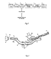
- Fig. 1 is a block diagram of the optical fiber sensor according to the invention.
- the optical fiber sensor comprises, following the optical path, a light source 1, an optical fiber 4, the first end of which forms an optical filter 3 and the other end forms a spatial mode demultiplexer 5, an optical focusing element 6, a mirror 11 on the first face of the focusing optical element 6 and a detection system 10.
- the detection system 10 consists, in a first embodiment (fig. 2), of detectors 7a and 7b of a multiplier 8 and of an electronic circuit 9.
- the detectors are coupled to the multiplier and the circuit 9 receives the detector output signals and the multiplier output signal s, and provides a signal p of disturbance position and amplitude A of the disturbance.
- the detectors 7a and 7b are connected to a spectral intensity measurement system 12.
- the spatial demultiplexing optical fiber sensor comprises, in addition to the optical fiber 4, a light source 1 provided for injecting a single mode into the optical fiber 4, either the fundamental guided mode LP01, or the polarization mode TE.
- the filtering of modes other than the fundamental mode LP01 or the polarization mode TE is carried out at the input of the waveguide 4 by the optical filter 3.
- Optical fiber 4 which is single mode in a given wavelength range, for example around 1.3 ⁇ m, in fact propagates waves of shorter wavelength, for example 0.8 ⁇ m.
- the optical fiber 4 can be subjected to one or more disturbances, localized or distributed, generated by the physical or chemical quantity to be measured. Under the effect of such a disturbance, the injected mode propagating in the optical fiber 4 can be coupled to a higher order mode. The two modes then propagate in the guide with a coupling rate depending on the amplitude of the disturbance.
- the coupled modes are separated spatially out of the waveguide 4 by the spatial mode demultiplexer 5 and are in the form of superimposed half-moons, as described by WV Sorin et al. "Phase-velocity measurements using prism output coupling for single and few-mode optical fibers", Optics Letters / Vol. 11 No. 2 / February 1986 / pp. 106-108.
- a focusing optical element 6 focuses each of the modes at as many distinct points and amplifies their spatial separation.
- the determination of the phase of the output signal s of the multiplier 8 provides the position p of the disturbance.
- the measurement of the intensities of the modes at a given wavelength makes it possible to define the position of the disturbance.
- the measurement of the light intensity of each spatially separated wave makes it possible to define the amplitude A of the disturbance.
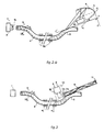
- Fig. 2 represents a first exemplary embodiment according to which the light source 1 is a multimode laser diode modulated in amplitude at a frequency of 10 MHz by an amplitude modulator 2.
- the modes other than the fundamental guided mode LP01 are filtered with entry of the optical fiber 4 by an optical filter 3.
- This is constituted by a laterally polished fiber in which only the fundamental mode remains guided, the higher order modes being purged towards the outside.
- the index n1 of the external medium surrounding said polished fiber must satisfy the relation: n11 ⁇ n1 ⁇ n01, n01 and n11 representing, respectively, the effective indices of the fundamental mode LP01 and of the order mode a LP11.
- the spatial mode demultiplexer 5 is a curved fiber and comprising a polished zone, the effective index of each mode is less than the external index n1 ′ and the polished zone of which is coupled by bonding to a focusing optical element 6.
- the medium of index n1 ′ situated between the polished zone of the optical fiber and the half-cylinder forming the focusing optical element 6 is an epoxy adhesive of index greater than the index of the core of the fiber.
- Said focusing optical element 6 consists of a half-cylinder with optically polished surfaces and produced in a Schott Mainz type BK7 glass of index 1.51, with a radius of 15 mm and a length of 150 mm.
- a mirror 11 is placed at the end of the half-cylinder so that the wave propagates a second time through the focusing optical element 6, thus producing an amplification of the modal separation.
- said element comprises a parabolic reflecting surface shown in FIG. 2.a.
- Said reflecting surface is obtained after rotation of a parabola around an axis parallel to the axis (Y, Y ′) of the section of the polished fiber.
- Said parabola is characterized by a focal length f and a main axis (Y1, Y1 ′) making an angle ⁇ with said axis (Y, Y ′).
- the angle ⁇ corresponds to the mean leakage angle of the modes in the external environment of high index n1 ′.
- the parabolic surface is expressed, in a coordinate system (X, Y) comprising the axis (Y, Y ′) of the polished fiber section, by the expression:
- the focusing optical element in accordance with the preferred embodiment above, is produced in a Schott Mainz type BK7 glass with a refractive index of 1.51.
- the focal length f of the dish has, for example, a value of 40 mm.
- the angle ⁇ is typically of the order of 25 °.
- the focusing optical element spatially separates the modes and focuses the two beams. Said focusing is carried out along the two axes (X, X ′) and (Z, Z ′) and reveals two light points.
- Each spatially separate mode is then detected separately using detectors 7a and 7b, the outputs of which are connected to a multiplier 8.
- the electronic circuit 9 determines the position p and the amplitude A of the disturbance from the signals from the detectors 7 and multiplier 8.
- Fig. 3 shows a second embodiment where the light source 1 is constituted by a combination of light-emitting diodes such as that described by G. Piffaretti et al./"Measurement of series of single mode fibers "/ New switching device lowing automatic OTDR / EFOC 88.
- the spectral width of the source thus obtained is of the order of 400 nm.
- the transducers 41, 4 N distributed along the fiber are in a limited number N of the order of 10 and each generate micro-curvatures of different spatial periods ⁇ i .
- the N transducers 41 to 4 N can be simultaneously active. After spatial separation of the modes, the detection relates to the light intensity of each mode at the N wavelengths present and is carried out using a spectral analysis system 12.
- Each of the N spatial periods being associated with a wavelength of the source, a detection at one of these wavelengths allows the one-to-one determination of the active coupling carried out at any one of the N transducers, hence the position of the disturbance.
- the light intensity of each mode provides information on the amplitude of the disturbance.
- the fiber optic sensor generally consists a light source 1 coupled to an optical filter 3 which can either be a polished fiber as described by RA BERGH et al., "Single-mode fiber-optic polarizer," Optics Letters / Vol.5, No.11 / November 1980, pp. 479-481; either two fibers - one bimodal, the other single-mode - connected end to end or a fiber bevelled by stretching under high temperature (CfV SHAH et al. / "Biconical tapered fiber-mode filter for bimodal systems" / OFC 88 / WQ 13).
- the optical fiber 4 is a single mode fiber at a given wavelength and operating at a lower wavelength, the modes liable to propagate being guided modes: fundamental mode LP01, order mode a LP11 and modes of higher order.
- the spatial mode demultiplexer 5 is a fiber bevelled by stretching under high temperature or else a polished fiber such as those used in the directional couplers described by Roger H. STOLEN et al. "Polarization-Selective Fiber Directional Coupler," Journal of Lightwave Technology / Vol. LT-3, No. 5 / October 1985 / pp. 1125-1129.
- Such a polished fiber is associated with a focusing element 6 with a refractive index close to or equal to the index of the core of the fiber and disposed on the polished edge of said fiber.
- the optical fiber 4 can also be a birefringent fiber propagating TE and TM polarization modes.
Landscapes
- Physics & Mathematics (AREA)
- General Physics & Mathematics (AREA)
- Optical Transform (AREA)
- Instruments For Measurement Of Length By Optical Means (AREA)
- Investigating Or Analysing Materials By Optical Means (AREA)
Applications Claiming Priority (2)
| Application Number | Priority Date | Filing Date | Title |
|---|---|---|---|
| CH345088A CH678226A5 (de) | 1988-09-16 | 1988-09-16 | |
| CH3450/88 | 1988-09-16 |
Publications (3)
| Publication Number | Publication Date |
|---|---|
| EP0359705A2 true EP0359705A2 (de) | 1990-03-21 |
| EP0359705A3 EP0359705A3 (en) | 1990-11-28 |
| EP0359705B1 EP0359705B1 (de) | 1994-03-02 |
Family
ID=4256207
Family Applications (1)
| Application Number | Title | Priority Date | Filing Date |
|---|---|---|---|
| EP19890810643 Expired - Lifetime EP0359705B1 (de) | 1988-09-16 | 1989-08-31 | Bimodaler faseroptischer Sensor mit räumlicher Demultiplexage |
Country Status (3)
| Country | Link |
|---|---|
| EP (1) | EP0359705B1 (de) |
| CH (1) | CH678226A5 (de) |
| DE (1) | DE68913408T2 (de) |
Cited By (2)
| Publication number | Priority date | Publication date | Assignee | Title |
|---|---|---|---|---|
| WO2011027016A1 (es) * | 2009-09-07 | 2011-03-10 | Universidad Pública de Navarra | Sensores de fibra óptica recubierta basados en resonancia originada por modos con pérdidas cercanos a la condición de corte |
| WO2018164900A1 (en) * | 2017-03-08 | 2018-09-13 | Alcatel-Lucent Usa Inc. | Multimode fiber sensor and sensing using forward and backward scattering |
Families Citing this family (1)
| Publication number | Priority date | Publication date | Assignee | Title |
|---|---|---|---|---|
| EP3677874A1 (de) * | 2019-01-02 | 2020-07-08 | Nokia Technologies Oy | Erkennung von ungleichmässigkeiten in einer optischen faser |
Family Cites Families (3)
| Publication number | Priority date | Publication date | Assignee | Title |
|---|---|---|---|---|
| US4342907A (en) * | 1977-12-12 | 1982-08-03 | Pedro B. Macedo | Optical sensing apparatus and method |
| GB8332409D0 (en) * | 1983-12-05 | 1984-01-11 | Gen Electric Co Plc | Fibre optic sensors |
| GB2155621B (en) * | 1984-03-06 | 1988-01-06 | Standard Telephones Cables Ltd | Optical fibre sensors |
-
1988
- 1988-09-16 CH CH345088A patent/CH678226A5/fr not_active IP Right Cessation
-
1989
- 1989-08-31 EP EP19890810643 patent/EP0359705B1/de not_active Expired - Lifetime
- 1989-08-31 DE DE1989613408 patent/DE68913408T2/de not_active Expired - Fee Related
Cited By (3)
| Publication number | Priority date | Publication date | Assignee | Title |
|---|---|---|---|---|
| WO2011027016A1 (es) * | 2009-09-07 | 2011-03-10 | Universidad Pública de Navarra | Sensores de fibra óptica recubierta basados en resonancia originada por modos con pérdidas cercanos a la condición de corte |
| ES2363285A1 (es) * | 2009-09-07 | 2011-07-28 | Universidad Publica De Navarra | Sensores de fibra optica recubierta basados en resonancia originada por modos con perdidas cercanos a la condicion de corte. |
| WO2018164900A1 (en) * | 2017-03-08 | 2018-09-13 | Alcatel-Lucent Usa Inc. | Multimode fiber sensor and sensing using forward and backward scattering |
Also Published As
| Publication number | Publication date |
|---|---|
| EP0359705A3 (en) | 1990-11-28 |
| EP0359705B1 (de) | 1994-03-02 |
| CH678226A5 (de) | 1991-08-15 |
| DE68913408T2 (de) | 1994-09-29 |
| DE68913408D1 (de) | 1994-04-07 |
Similar Documents
| Publication | Publication Date | Title |
|---|---|---|
| Liu et al. | Diaphragm based long cavity Fabry–Perot fiber acoustic sensor using phase generated carrier | |
| Kobayashi et al. | Polarization-independent interferometric optical-time-domain reflectometer | |
| US4238856A (en) | Fiber-optic acoustic sensor | |
| US20200249075A1 (en) | Method and apparatus for distributed sensing | |
| KR101000974B1 (ko) | 간섭무늬 측정시스템을 이용한 광도파로샘플의 색분산 특성측정방법 | |
| EP0564366B1 (de) | Faseroptischer Belastungsdetektor | |
| EP3066423B1 (de) | Verteilte erfassungsvorrichtung mit single-end-brillouin-glasfasersensoren und verfahren | |
| EP0326476B1 (de) | Fiberoptisches Hydrophon und Antenne, die eine Reihe von Hydrophonen umfasst | |
| CN1294401C (zh) | 干涉测量装置 | |
| EP0260894A1 (de) | Faseroptisches Messsystem | |
| EP0418202B1 (de) | Optischer Sensor mit Modeninterferenzmessung | |
| Peternella et al. | Interrogation of a ring-resonator ultrasound sensor using a fiber Mach-Zehnder interferometer | |
| EP0359705B1 (de) | Bimodaler faseroptischer Sensor mit räumlicher Demultiplexage | |
| EP2598834B1 (de) | Interferometrischer faseroptischer sensor zum messen eines physikalischen parameters | |
| EP3973256B1 (de) | Faseroptischer akustischer sensor und zugehöriges messsystem, fahrzeug und messverfahren | |
| JPH076862B2 (ja) | 光フアイバ圧力センサ | |
| RU2057285C1 (ru) | Волоконно-оптический датчик перемещений | |
| JP3287441B2 (ja) | 光線路識別用光部品並びにその遠隔測定方法及び装置 | |
| FR2703451A1 (fr) | Dispositif de mesure interférométrique en lumière polarisée. | |
| EP0591912B1 (de) | Interferometer, bestehend aus einer integrierten Anordnung und einem Spiegel, die durch eine Messzone voneinander getrennt sind | |
| Gritsenko et al. | Distributed Strain Sensor Based on Double-Wavelength phi-OTDR | |
| Grillo Peternella | The Fourier transform interrogator | |
| Cole et al. | Advances in fiber optic based acoustic sensors | |
| SU1024764A1 (ru) | Устройство дл измерени давлени | |
| Zheng | Triple-sensor multiplexed reflectometric fiber-optic FMCW displacement sensor |
Legal Events
| Date | Code | Title | Description |
|---|---|---|---|
| PUAI | Public reference made under article 153(3) epc to a published international application that has entered the european phase |
Free format text: ORIGINAL CODE: 0009012 |
|
| AK | Designated contracting states |
Kind code of ref document: A2 Designated state(s): CH DE FR GB LI |
|
| PUAL | Search report despatched |
Free format text: ORIGINAL CODE: 0009013 |
|
| AK | Designated contracting states |
Kind code of ref document: A3 Designated state(s): CH DE FR GB LI |
|
| 17P | Request for examination filed |
Effective date: 19910510 |
|
| 17Q | First examination report despatched |
Effective date: 19920527 |
|
| GRAA | (expected) grant |
Free format text: ORIGINAL CODE: 0009210 |
|
| AK | Designated contracting states |
Kind code of ref document: B1 Designated state(s): CH DE FR GB LI |
|
| REF | Corresponds to: |
Ref document number: 68913408 Country of ref document: DE Date of ref document: 19940407 |
|
| GBT | Gb: translation of ep patent filed (gb section 77(6)(a)/1977) |
Effective date: 19940608 |
|
| REG | Reference to a national code |
Ref country code: CH Ref legal event code: PUE Owner name: FIMY LIMITED |
|
| PGFP | Annual fee paid to national office [announced via postgrant information from national office to epo] |
Ref country code: GB Payment date: 19940824 Year of fee payment: 6 |
|
| PLBE | No opposition filed within time limit |
Free format text: ORIGINAL CODE: 0009261 |
|
| STAA | Information on the status of an ep patent application or granted ep patent |
Free format text: STATUS: NO OPPOSITION FILED WITHIN TIME LIMIT |
|
| 26N | No opposition filed | ||
| REG | Reference to a national code |
Ref country code: FR Ref legal event code: TP |
|
| PG25 | Lapsed in a contracting state [announced via postgrant information from national office to epo] |
Ref country code: GB Effective date: 19950831 |
|
| GBPC | Gb: european patent ceased through non-payment of renewal fee |
Effective date: 19950831 |
|
| PGFP | Annual fee paid to national office [announced via postgrant information from national office to epo] |
Ref country code: FR Payment date: 19970613 Year of fee payment: 9 |
|
| PGFP | Annual fee paid to national office [announced via postgrant information from national office to epo] |
Ref country code: CH Payment date: 19970710 Year of fee payment: 9 |
|
| PGFP | Annual fee paid to national office [announced via postgrant information from national office to epo] |
Ref country code: DE Payment date: 19971002 Year of fee payment: 9 |
|
| PG25 | Lapsed in a contracting state [announced via postgrant information from national office to epo] |
Ref country code: LI Free format text: LAPSE BECAUSE OF NON-PAYMENT OF DUE FEES Effective date: 19980831 Ref country code: CH Free format text: LAPSE BECAUSE OF NON-PAYMENT OF DUE FEES Effective date: 19980831 |
|
| REG | Reference to a national code |
Ref country code: CH Ref legal event code: PL |
|
| PG25 | Lapsed in a contracting state [announced via postgrant information from national office to epo] |
Ref country code: FR Free format text: LAPSE BECAUSE OF NON-PAYMENT OF DUE FEES Effective date: 19990430 |
|
| PG25 | Lapsed in a contracting state [announced via postgrant information from national office to epo] |
Ref country code: DE Free format text: LAPSE BECAUSE OF NON-PAYMENT OF DUE FEES Effective date: 19990601 |
|
| REG | Reference to a national code |
Ref country code: FR Ref legal event code: ST |