EP0564366B1 - Faseroptischer Belastungsdetektor - Google Patents
Faseroptischer Belastungsdetektor Download PDFInfo
- Publication number
- EP0564366B1 EP0564366B1 EP93400858A EP93400858A EP0564366B1 EP 0564366 B1 EP0564366 B1 EP 0564366B1 EP 93400858 A EP93400858 A EP 93400858A EP 93400858 A EP93400858 A EP 93400858A EP 0564366 B1 EP0564366 B1 EP 0564366B1
- Authority
- EP
- European Patent Office
- Prior art keywords
- fibre
- electrical signal
- optical
- signal
- phase
- Prior art date
- Legal status (The legal status is an assumption and is not a legal conclusion. Google has not performed a legal analysis and makes no representation as to the accuracy of the status listed.)
- Expired - Lifetime
Links
- 239000000835 fiber Substances 0.000 title claims description 76
- 238000005259 measurement Methods 0.000 claims description 41
- 230000010363 phase shift Effects 0.000 claims description 25
- 239000013307 optical fiber Substances 0.000 claims description 22
- 230000003287 optical effect Effects 0.000 claims description 19
- 238000001514 detection method Methods 0.000 claims description 11
- 238000000034 method Methods 0.000 description 19
- 238000000253 optical time-domain reflectometry Methods 0.000 description 7
- 230000035939 shock Effects 0.000 description 7
- 238000012546 transfer Methods 0.000 description 7
- 230000008878 coupling Effects 0.000 description 6
- 238000010168 coupling process Methods 0.000 description 6
- 238000005859 coupling reaction Methods 0.000 description 6
- 238000002168 optical frequency-domain reflectometry Methods 0.000 description 6
- 230000006835 compression Effects 0.000 description 5
- 238000007906 compression Methods 0.000 description 5
- 238000000691 measurement method Methods 0.000 description 5
- 230000010287 polarization Effects 0.000 description 5
- 230000008901 benefit Effects 0.000 description 4
- 230000007547 defect Effects 0.000 description 4
- 238000002310 reflectometry Methods 0.000 description 4
- 230000035945 sensitivity Effects 0.000 description 4
- 230000005540 biological transmission Effects 0.000 description 3
- 230000000694 effects Effects 0.000 description 3
- 238000005305 interferometry Methods 0.000 description 3
- 101100536354 Drosophila melanogaster tant gene Proteins 0.000 description 2
- 239000002131 composite material Substances 0.000 description 2
- 238000012423 maintenance Methods 0.000 description 2
- YFXPPSKYMBTNAV-UHFFFAOYSA-N bensultap Chemical compound C=1C=CC=CC=1S(=O)(=O)SCC(N(C)C)CSS(=O)(=O)C1=CC=CC=C1 YFXPPSKYMBTNAV-UHFFFAOYSA-N 0.000 description 1
- 238000010276 construction Methods 0.000 description 1
- 230000032798 delamination Effects 0.000 description 1
- 230000001934 delay Effects 0.000 description 1
- 230000001066 destructive effect Effects 0.000 description 1
- 238000005516 engineering process Methods 0.000 description 1
- 239000012510 hollow fiber Substances 0.000 description 1
- 238000003780 insertion Methods 0.000 description 1
- 230000037431 insertion Effects 0.000 description 1
- 238000004519 manufacturing process Methods 0.000 description 1
- 238000012544 monitoring process Methods 0.000 description 1
- 238000003012 network analysis Methods 0.000 description 1
- 238000000711 polarimetry Methods 0.000 description 1
- 239000004065 semiconductor Substances 0.000 description 1
- 238000012360 testing method Methods 0.000 description 1
- 230000000930 thermomechanical effect Effects 0.000 description 1
Images


Classifications
-
- G—PHYSICS
- G01—MEASURING; TESTING
- G01M—TESTING STATIC OR DYNAMIC BALANCE OF MACHINES OR STRUCTURES; TESTING OF STRUCTURES OR APPARATUS, NOT OTHERWISE PROVIDED FOR
- G01M11/00—Testing of optical apparatus; Testing structures by optical methods not otherwise provided for
- G01M11/08—Testing mechanical properties
- G01M11/083—Testing mechanical properties by using an optical fiber in contact with the device under test [DUT]
-
- G—PHYSICS
- G01—MEASURING; TESTING
- G01L—MEASURING FORCE, STRESS, TORQUE, WORK, MECHANICAL POWER, MECHANICAL EFFICIENCY, OR FLUID PRESSURE
- G01L1/00—Measuring force or stress, in general
- G01L1/24—Measuring force or stress, in general by measuring variations of optical properties of material when it is stressed, e.g. by photoelastic stress analysis using infrared, visible light, ultraviolet
- G01L1/242—Measuring force or stress, in general by measuring variations of optical properties of material when it is stressed, e.g. by photoelastic stress analysis using infrared, visible light, ultraviolet the material being an optical fibre
Definitions
- the invention relates to a fiber optic stress detector and in particular a device for detecting the stresses applied to an optical fiber.
- These stresses can be elongation or compression stresses along the axis of the fiber, pressure forces (shocks) perpendicular to the axis of the fiber, deformations (curvatures), temperature variations having the effect of vary the refractive index of the fiber.
- This invention applies to the control of damage to structures and in particular to composite structures by non-destructive techniques. It is applicable for example, to the control of civil engineering works (bridge, dams) or to the control of deformations of aircraft structures.
- the damage control of composite structures can be achieved by the insertion of fiber optic sensors. This method is described in French Patent Application No. 91 15347 (EP-A1-546 899 publication 16.6.93). This method is particularly well suited to monitoring deformations or detecting delamination in fatigue.
- the damage control of structures can be carried out by using a transfer by bonding on the structure to be controlled of an assembly consisting of a rigid element and an optical fiber as described in French Patent Application n ° 92 03006 (FR-A1-2 688 584 publication 17.9.93). All these systems have in common a measurement method using an optical interferometer of the Michelson type.
- the invention makes it possible to overcome this optical interferometry by transferring detection in the microwave domain.
- the reflectometry is based on the radar principle: a light pulse is injected into the optical fiber, the reflected light (i.e. the light backscattered on a defect in the fiber or on a connector or splice) is measured by means of a detector. The location of the faults is obtained by measuring the time difference between the time T 0 of transmission of the signal and the time T 1 of the return of the signal after reflection on the fault.
- the main advantage of the OTDR resides in its relative simplicity and its operation on any type of fiber.
- Frequency domain reflectometry uses a technique very similar to microwave network analysis methods.
- the optical carrier is frequency modulated.
- the modulation of the carrier is then varied, by frequency hopping, in the widest possible frequency range.
- the optical response of the system under test is measured by heterodyne detection providing the amplitude and phase for each frequency.
- the response in the time domain is obtained after Inverse Fourier Transform.
- the field of frequency ramp technology includes the applications of radar techniques at OFDR.
- the laser source is frequency modulated.
- a frequency ramp applied to the laser source allows to locate the defects of an optical fiber by measuring the delay between the emission and the echo received by backscattering.
- Interfero-polarimetric methods are based on Michelson type optical interferometry.
- the main advantage of this method comes from the sensitivity of the hollow fiber structure (FASE) as a pressure or deformation sensor and the use of interferometry.
- FASE hollow fiber structure
- the subject of the invention is a detector based on a different technique and based in particular on microwave phase shift measurements.
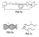
- the device of FIG. 1 a comprises a fiber 1 which receives a light beam 4 from an optical source 2.
- the light beam 4 is amplitude modulated.
- the light beam 4 is of the type shown in Figure 1b.
- the light beam 4 is transmitted by the fiber 1 to a demodulation device 6 which supplies a demodulated signal such as the signal 9 in FIG. 1c.
- This signal 9 is transmitted to a phase-shift measurement device 10.
- This device 10 also receives a signal 19 derived from the electrical modulation signal 11 and which measures the phase shift existing between the signals 9 and 19.
- the signal 19 can be derived directly from the signal 11 and can simply be subjected to a delay (by a device not shown) corresponding to the transmission time of the beam 4 and of the signal 9.
- the signals 9 and 19 are normally in phase or in a determined and known phase relationship.
- the transmission time of the light beam 4 varies, the signals 9 and 19 undergo a phase shift variation ( ⁇ ⁇ in FIG. 1c) and the device 10 measures this phase shift.
- the modulation frequency (signal frequency 11) can, depending on the use of the device, have a value for example between 1 GHz and several tens of GHz.
- the source 2 may be, for example, a laser diode amplitude modulated by a microwave signal, the frequency of which will be chosen as a function of the desired spatial resolution and of the phase precision accessible by microwave measurements.
- This microwave signal on an optical carrier is injected into the optical fiber which can be single-mode or polarization-maintaining and which plays the role of intrinsic sensor.
- the application of a stress or a deformation on the optical fiber creates a variation in the refractive index of the medium, resulting in a phase shift or a delay of the measurement signal relative to the reference signal.
- the beam 4 after demodulation detection gives a microwave signal 9.
- the two microwave signals 9 and 19 supplied are amplified and then injected into an amplitude-phase demodulator providing a signal (a voltage) proportional to the phase shift of the two signals 9 and 19.
- a laser diode 2 is amplitude modulated by a radiofrequency signal 11, the frequency of which will be chosen as a function of the desired spatial resolution and of the phase precision accessible by microwave measurements.
- This microwave signal 11 on optical carrier 4 is injected into the optical fiber 1 playing the role of intrinsic sensor.
- a deformation such as for example an elongation or compression on the optical fiber creates a variation in the refractive index of the medium resulting in a phase shift of the measurement signal 9 with respect to the reference signal 19.
- the measurement signal will be demodulated by a detector 6 having a bandwidth compatible with the modulation frequency of the source laser diode 2.
- the demodulated signal and the modulation reference signal are amplified by amplifiers 7 and 8.
- the comparison of the reference signal 19 and the measurement signal 9 by the device 10 provides a measurement of phase shift proportional to the elongation or the compression of the measurement optical fiber.
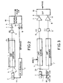
- the device of FIG. 3 is a variant of that of FIG. 2. It is used here for example for detecting a localized stress such as an impact (shock for example).
- This device comprises a measuring fiber 1 and a reference fiber 1 'not subjected to stresses.
- the source 2 supplies a modulated light beam as before to a beam splitter 20 which divides the beam into two parts towards the two fibers 1 and 1 '.
- Detectors 6 and 6 demodulate the beams transmitted by the fibers.
- the signals demodulated and then amplified by the amplifiers 7 and 8 are transmitted to a phase-shift measurement device 10.
- the measurement method performed by the device of FIG. 4 is based on the measurement of the phase shift (or of the delay) between two microwave signals transmitted on a single optical channel.
- the device of FIG. 4 mainly comprises an optical fiber 1 with polarization maintenance receiving a light beam 4 polarized by a polarizer 12.
- the laser diode 2 is amplitude modulated by an alternating signal 11 (for example radiofrequency), the frequency of which will be chosen as a function of the desired spatial resolution and of the phase precision accessible by microwave measurements.
- an alternating signal 11 for example radiofrequency
- the alternating signal 11 on an optical carrier is injected into the polarization-maintaining optical fiber 1 playing the role of intrinsic sensor (a fiber with a hollow FASE structure, for example).
- This fiber has two orthogonal propagation modes (a slow axis and a fast axis).
- One of the polarization modes will serve as a reference channel (the fast axis for example), a coupling point will induce energy transfer in the second mode (the slow axis).
- the two signals will arrive with a delay proportional to the difference in propagation speed between the slow axis and the fast axis and proportional to the length of the fiber crossed after the coupling point.
- the two signals 9 ′ and 19 ′ are demodulated by the detectors 14 and 15 having a bandwidth compatible with the modulation frequency of the source laser diode 2.
- the two microwave signals supplied by the two detectors 14 and 15 are amplified (amplifiers 7 and 8) then injected into an amplitude-phase demodulator 10 providing a signal (a voltage) proportional to the phase shift of the two channels.
- the value of the phase shift measured by the device 10 translates the distance separating the point of impact from the disturbance and the output of the fiber 1. This phase shift therefore makes it possible to locate the position of the point of impact on the fiber.
- the intensity of the signal resulting from the transfer of energy to the point of impact gives an indication of the intensity of the coupling and therefore of the intensity of the impact.
- a device 15 for measuring the intensity of the signal resulting from the energy transfer indicates the value of the impact.
- the modulation signal 11 comprises a succession of successive modulation frequencies.
- these frequencies are in the form of alternations of different frequencies either continuously variable or variable in successive steps. In this way, several impacts can be detected simultaneously on the fiber 1 by identifying the frequency which gave rise to an energy transfer.
- the various devices described in the foregoing operate with a single passage of the light beam 4 in the fiber 1.
- a reflection device 16 such as light after having traversed the fiber 1 is reflected and traverses the fiber in the opposite direction.
- a semi-reflecting device 17 reflects at least part of the light coming from the fiber towards the detection devices and in particular the phase-shift measurement device 10.
- the device 17 is a semi-reflecting device, but it could be a coupling device produced in integrated optics making it possible to transmit the light coming from the fiber to the device 10.
- FIG. 6 represents a variant of the device of the invention according to which the optical source 2 transmits a modulated beam which is distributed towards several measurement fibers 1.0 to 1.n by a beam splitter 18.
- reflection devices return the light transmitted by the different fibers to a coupler 17 which retransmits the reflected light to the measurement device 10.
- the device of FIG. 6 therefore makes it possible to integrate the effects of several constraints simultaneously affecting several measurement fibers.
- the integrated electronics that can be used in the reading system allow use in flight of the damage control, which can be important for airborne applications.
- this system provides information in "real time" of the controlled structure.
- the devices described do not require a specific fiber but can operate with conventional single-mode fibers.
- this measure For applications to the control of damage to structures, this measure will find its application in structures subjected to stresses, deformations or shocks such as for example civil engineering structures, structures airborne or storage tanks. These measures extend to the case of cracks in constructions (building, building, ).
Landscapes
- Physics & Mathematics (AREA)
- General Physics & Mathematics (AREA)
- Chemical & Material Sciences (AREA)
- Analytical Chemistry (AREA)
- Length Measuring Devices By Optical Means (AREA)
Claims (8)
- Lichtleitfaser-Detektor von Beanspruchungen, mit wenigstens einer Lichtleitfaser (1) und einer Lichtquelle (2), die in die Lichtleitfaser ein Lichtstrahlenbündel (4) sendet, dadurch gekennzeichnet, daß er enthält:- eine Vorrichtung (3) zur Amplitudenmodulation des Lichtstrahlenbündels (4), die durch wenigstens ein elektrisches Modulationsfrequenzsignal (11) gesteuert wird;- eine Erfassungsvorrichtung, die mit der Faser verbunden ist und das modulierte Lichtstrahlenbündel, nach dem es wenigstens durch eine Zone der Faser gelaufen ist, in ein elektrisches Meßsignal umwandelt und die Phasenverschiebung mißt, die zwischen diesem elektrischen Meßsignal und dem elektrischen Modulationsfrequenzsignal (11) oder einem aus diesem elektrischen Signal abgeleiteten Signal vorhanden ist.
- Lichtleitfaser-Detektor nach Anspruch 1, dadurch gekennzeichnet, daß:- die Erfassungsvorrichtung eine erste optische Erfassungsvorrichtung und einen Amplitudendemodulator (6) enthält, die das modulierte Strahlenbündel erfassen und ein demoduliertes elektrisches Signal (9) liefern;und dadurch, daß er enthält:- eine Phasenverschiebungs-Meßvorrichtung (10), die das demodulierte elektrische Signal (9) und das elektrische Frequenzsignal (11) oder ein aus diesem elektrischen Signal (11) abgeleitetes elektrisches Signal (19) empfängt und ein Phasenverschiebungssignal liefert.
- Lichtleitfaser-Detektor nach Anspruch 1, dadurch gekennzeichnet, daß das elektrische Frequenzsignal ein Hochfrequenz- oder Höchstfrequenzsignal ist.
- Lichtleitfaser-Detektor nach Anspruch 2, dadurch gekennzeichnet, daß die Lichtleitfaser (1) eine Einmodenfaser ist.
- Lichtleitfaser-Detektor nach Anspruch 2, dadurch gekennzeichnet, daß er einen Strahlteiler (20), der einen Teil des modulierten Strahlenbündels (4) an eine keiner Beanspruchung unterliegende Referenzfaser (1') umleitet, und eine zweite Erfassungs- und Amplitudendemodulationsvorrichtung (6') enthält, die mit der Referenzfaser (1') verbunden ist und zur Phasenverschiebungs-Meßvorrichtung (10) statt des elektrischen Frequenzsignals (11) ein demoduliertes Referenzsignal (19) liefert.
- Lichtleitfaser-Detektor nach Anspruch 1, dadurch gekennzeichnet, daß die Lichtleitfaser (1) eine Lichtleitfaser mit Polarisationserhaltung ist und daß er am Eingang der Lichtleitfaser (1) einen Polarisator (12) und am Ausgang der Lichtleitfaser (1) einen Polarisationsteiler (13) enthält, wobei jede Polarisation durch Demodulatoren (14 und 15) demoduliert wird und an die Phasenverschiebungs-Meßvorrichtung (10) übertragen wird.
- Lichtleitfaser-Detektor nach Anspruch 1, dadurch gekennzeichnet, daß er am Ausgang der Meßfaser (1) eine Reflektionsvorrichtung, die das Licht in die Faser zurückschickt, und ferner einen Strahlteiler (17) enthält, der sich am Eingang der Meßfaser (1) befindet und wenigstens einen Teil des von der Faser (1) kommenden Lichts an die Phasenverschiebungs-Meßvorrichtung (10) überträgt.
- Lichtleitfaser-Detektor nach Anspruch 7, dadurch gekennzeichnet, daß er mehrere Meß-Lichtleitfasern (1.0 bis 1.n) enthält, die von der Lichtquelle (2) über einen Strahlenbündelverteiler (18) jeweils ein moduliertes Strahlenbündel empfangen, wobei jede Faser am Faserausgang eine Reflektions-vorrichtung enthält, wobei der Strahlteiler (17) das von den verschiedenen Fasern kommende Licht an die Phasenverschiebungs-Meßvorrichtung (10) überträgt.
Applications Claiming Priority (2)
| Application Number | Priority Date | Filing Date | Title |
|---|---|---|---|
| FR9204000A FR2689632B1 (fr) | 1992-04-02 | 1992-04-02 | Detecteur a fibre optique de contraintes. |
| FR9204000 | 1992-04-02 |
Publications (2)
| Publication Number | Publication Date |
|---|---|
| EP0564366A1 EP0564366A1 (de) | 1993-10-06 |
| EP0564366B1 true EP0564366B1 (de) | 1997-05-21 |
Family
ID=9428385
Family Applications (1)
| Application Number | Title | Priority Date | Filing Date |
|---|---|---|---|
| EP93400858A Expired - Lifetime EP0564366B1 (de) | 1992-04-02 | 1993-04-02 | Faseroptischer Belastungsdetektor |
Country Status (4)
| Country | Link |
|---|---|
| US (1) | US5381005A (de) |
| EP (1) | EP0564366B1 (de) |
| DE (1) | DE69310803T2 (de) |
| FR (1) | FR2689632B1 (de) |
Families Citing this family (24)
| Publication number | Priority date | Publication date | Assignee | Title |
|---|---|---|---|---|
| FR2706606B1 (fr) * | 1993-06-15 | 1995-07-21 | Thomson Csf | Capteur à fibre optique reconfigurable. |
| FR2706607B1 (fr) * | 1993-06-15 | 1995-07-21 | Thomson Csf | Capteur de température multipoints reconfigurable. |
| JPH07128155A (ja) * | 1993-09-13 | 1995-05-19 | Tokyo Electric Power Co Inc:The | 応力測定方法及びその測定システム |
| NO303470B1 (no) * | 1994-12-16 | 1998-07-13 | Safety One As | FremgangsmÕte og system til kontinuerlig og global overvÕking av dynamiske belastninger |
| US5661246A (en) * | 1996-04-01 | 1997-08-26 | Wanser; Keith H. | Fiber optic displacement sensor for high temperature environment |
| US5737067A (en) * | 1996-04-18 | 1998-04-07 | The United States Of America As Represented By The Secretary Of The Navy | Length and elongation sensor |
| US6354152B1 (en) | 1996-05-08 | 2002-03-12 | Edward Charles Herlik | Method and system to measure dynamic loads or stresses in aircraft, machines, and structures |
| US5900556A (en) * | 1997-09-15 | 1999-05-04 | Ahmad; Falih H. | Helical optical fiber strain sensor |
| FR2769154B1 (fr) * | 1997-09-30 | 1999-12-03 | Thomson Csf | Dispositif de synchronisation precise |
| US6571639B1 (en) * | 1999-03-01 | 2003-06-03 | Luna Innovations, Inc. | Fiber optic system |
| US7792614B2 (en) * | 2003-08-27 | 2010-09-07 | Airbus Uk Limited | Apparatus and method suitable for measuring the global displacement or load on an aircraft component |
| EP1664707A1 (de) * | 2003-08-27 | 2006-06-07 | Airbus UK Limited | Messung der belastung, verschiebung auf einer flugzeugkomponente unter verwendung eines mikrowellen-strahls |
| US7578199B2 (en) * | 2003-08-27 | 2009-08-25 | Airbus Uk Limited | Apparatus and method suitable for measuring the displacement or load on an aircraft component |
| CN1910436B (zh) | 2004-01-23 | 2010-05-26 | Lm玻璃纤维有限公司 | 包括用于纤维增强结构中应变测量的温度补偿系统的装置 |
| US7605923B2 (en) * | 2004-10-15 | 2009-10-20 | Morgan Research Corporation | Embeddable polarimetric fiber optic sensor and method for monitoring of structures |
| ES2314527T3 (es) * | 2005-07-28 | 2009-03-16 | Fondazione Torino Wireless | Sistema y procedimiento para medicion de fuerzas. |
| US7498910B2 (en) * | 2006-07-28 | 2009-03-03 | Cooper Technologies Company | Ground fault circuit interrupter device |
| EP2193330B1 (de) * | 2007-09-17 | 2015-03-04 | Avago Technologies General IP (Singapore) Pte. Ltd | Faseropitscher sensor zur messung von verformungen an windkraftanlagen |
| US20090296746A1 (en) * | 2008-03-15 | 2009-12-03 | Morgan Research Corporation | Fiber laser coil form and related manufacturing techniques |
| GB0909512D0 (en) * | 2009-06-03 | 2009-07-15 | Airbus Uk Ltd | Weight measurement apparatus and method |
| US9337921B2 (en) * | 2013-11-14 | 2016-05-10 | Adva Optical Networking Se | Method and apparatus for monitoring mechanical fiber stress of optical fiber spans |
| US9435701B2 (en) * | 2014-01-29 | 2016-09-06 | Avago Technologies General Ip (Singapore) Pte. Ltd. | Optical fiber strain sensor system and method |
| CN105910992B (zh) * | 2016-05-06 | 2017-05-03 | 河海大学 | 一种基于分布式传感光纤的混凝土损伤动态诊断系统 |
| US11563405B2 (en) | 2018-04-30 | 2023-01-24 | Alliance For Sustainable Energy, Llc | Microwave photoconductance spectrometer and methods of using the same |
Family Cites Families (14)
| Publication number | Priority date | Publication date | Assignee | Title |
|---|---|---|---|---|
| JPS5651636A (en) * | 1979-10-01 | 1981-05-09 | Nippon Telegr & Teleph Corp <Ntt> | Measuring method for material dispersion characteristic of fiber |
| US4255017A (en) * | 1979-12-14 | 1981-03-10 | Bell Telephone Laboratories, Incorporated | Tunable source of coherent electromagnetic radiation based on modulational instability |
| EP0091826B1 (de) * | 1982-04-14 | 1989-11-15 | The Board Of Trustees Of The Leland Stanford Junior University | Fiber-optischer Sensor zum Detektieren sehr kleiner Verschiebungen einer Oberfläche |
| GB2144215B (en) * | 1983-07-28 | 1988-06-22 | Cise Spa | Interferometric detector with fibre-optic sensor |
| US4529876A (en) * | 1983-12-27 | 1985-07-16 | Walker Clifford G | Integrated optics transducer |
| US4750833A (en) * | 1985-12-03 | 1988-06-14 | Princeton Applied Research Corp. | Fiber optic dispersion method and apparatus |
| US4859843A (en) * | 1988-01-22 | 1989-08-22 | Hewlett-Packard Company | Method and apparatus for optical signal analysis using a gated modulation source and an optical delay circuit to achieve a self-homodyne receiver |
| US4921347A (en) * | 1988-01-25 | 1990-05-01 | Hewlett-Packard Company | Method and apparatus for calibrating a lightwave component measurement system |
| US4881813A (en) * | 1988-05-20 | 1989-11-21 | The United States Of America As Represented By The Secretary Of The Navy | Passive stabilization of a fiber optic nonlinear interferometric sensor |
| GB2224566A (en) * | 1988-06-30 | 1990-05-09 | British Aerospace | An optical sensor for determining changes in a dimension and/or a temperature of an object |
| US4929050A (en) * | 1988-10-31 | 1990-05-29 | Unisys Corporation | Traveling wave fiber optic interferometric sensor and method of polarization poling fiber optic |
| GB8900304D0 (en) * | 1989-01-06 | 1989-03-08 | Lucas Ind Plc | Signal extraction apparatus |
| IT1237486B (it) * | 1989-06-23 | 1993-06-07 | Agip Spa | Procedimento e dispositivo a sensori interferometrici a fibra ottica per l'analisi della deformazione dinamica di una struttura o di suoi componenti |
| FR2656095B1 (fr) * | 1989-12-19 | 1994-12-23 | Thomson Csf | Capteur a fibre optique. |
-
1992
- 1992-04-02 FR FR9204000A patent/FR2689632B1/fr not_active Expired - Fee Related
-
1993
- 1993-04-02 US US08/042,020 patent/US5381005A/en not_active Expired - Fee Related
- 1993-04-02 EP EP93400858A patent/EP0564366B1/de not_active Expired - Lifetime
- 1993-04-02 DE DE69310803T patent/DE69310803T2/de not_active Expired - Fee Related
Also Published As
| Publication number | Publication date |
|---|---|
| US5381005A (en) | 1995-01-10 |
| EP0564366A1 (de) | 1993-10-06 |
| DE69310803T2 (de) | 1997-10-23 |
| FR2689632B1 (fr) | 1997-09-19 |
| FR2689632A1 (fr) | 1993-10-08 |
| DE69310803D1 (de) | 1997-06-26 |
Similar Documents
| Publication | Publication Date | Title |
|---|---|---|
| EP0564366B1 (de) | Faseroptischer Belastungsdetektor | |
| Hotate et al. | Synthesis of optical-coherence function and its applications in distributed and multiplexed optical sensing | |
| CA2476805C (en) | Inline sagnac fiber optic sensor with modulation adjustment | |
| US7557930B2 (en) | Bessel beam interferometer and measurement method | |
| EP0434504A1 (de) | Fiberoptischer Messwandler | |
| EP3066423B1 (de) | Verteilte erfassungsvorrichtung mit single-end-brillouin-glasfasersensoren und verfahren | |
| EP3353502B1 (de) | Messsystem und temperatur und/oder formänderungssensor mit brillouinrückreflexionsanalyse | |
| KR20090001405A (ko) | 분포 광섬유 센서 시스템 | |
| EP0286466B1 (de) | Verfahren zum Anzeigen von Polarisationskupplungen in einem optischen System mit Doppelbrechung und dessen Anwendung bei der Montage der Komponenten eines optischen Systems | |
| CN100437050C (zh) | 分布式光纤振动传感器 | |
| EP0418202B1 (de) | Optischer Sensor mit Modeninterferenzmessung | |
| Takada et al. | High sensitivity and submillimeter resolution optical time-domain reflectometry based on low-coherence interference | |
| FR2520114A1 (fr) | Dispositif de localisation d'une cassure d'une fibre optique et utilisation d'un tel dispositif | |
| Eiselt et al. | Optical fiber for remote sensing with high spatial resolution | |
| CN115931105B (zh) | 一种单端分布式光纤振动传感器系统及信号处理方法 | |
| Xu et al. | Multiplexed point and stepwise-continuous fiber grating based sensors: practical sensor for structural monitoring? | |
| EP3973256B1 (de) | Faseroptischer akustischer sensor und zugehöriges messsystem, fahrzeug und messverfahren | |
| EP1674878B1 (de) | Elektrooptische Sonde zur Messung elektrischer oder elektromagnetischer Felder mit einer Steuerung der Wellenlänge des Betriebspunkts | |
| Kim et al. | OTDR based on Brillouin dynamic grating in an e-core two-mode fiber for simultaneous measurement of strain and temperature distribution | |
| EP0359705B1 (de) | Bimodaler faseroptischer Sensor mit räumlicher Demultiplexage | |
| Makhlouf et al. | Photon-Counting Optical Time Domain Reflectometer Using Superconducting Nanowire Single Photon Detector Based on Time to Digital Converter | |
| FR2703451A1 (fr) | Dispositif de mesure interférométrique en lumière polarisée. | |
| Niemi et al. | Device for frequency chirp measurements of optical transmitters in real time | |
| Gritsenko et al. | Distributed Strain Sensor Based on Double-Wavelength phi-OTDR | |
| KR20020090468A (ko) | 광섬유 브릴루앙 산란형 센서시스템 및 이를 이용한침입자 탐지방법 |
Legal Events
| Date | Code | Title | Description |
|---|---|---|---|
| PUAI | Public reference made under article 153(3) epc to a published international application that has entered the european phase |
Free format text: ORIGINAL CODE: 0009012 |
|
| AK | Designated contracting states |
Kind code of ref document: A1 Designated state(s): DE GB |
|
| RAP3 | Party data changed (applicant data changed or rights of an application transferred) |
Owner name: THOMSON-CSF |
|
| 17P | Request for examination filed |
Effective date: 19940228 |
|
| 17Q | First examination report despatched |
Effective date: 19960111 |
|
| GRAG | Despatch of communication of intention to grant |
Free format text: ORIGINAL CODE: EPIDOS AGRA |
|
| GRAH | Despatch of communication of intention to grant a patent |
Free format text: ORIGINAL CODE: EPIDOS IGRA |
|
| GRAH | Despatch of communication of intention to grant a patent |
Free format text: ORIGINAL CODE: EPIDOS IGRA |
|
| GRAA | (expected) grant |
Free format text: ORIGINAL CODE: 0009210 |
|
| AK | Designated contracting states |
Kind code of ref document: B1 Designated state(s): DE GB |
|
| REF | Corresponds to: |
Ref document number: 69310803 Country of ref document: DE Date of ref document: 19970626 |
|
| GBT | Gb: translation of ep patent filed (gb section 77(6)(a)/1977) |
Effective date: 19970619 |
|
| PLBE | No opposition filed within time limit |
Free format text: ORIGINAL CODE: 0009261 |
|
| STAA | Information on the status of an ep patent application or granted ep patent |
Free format text: STATUS: NO OPPOSITION FILED WITHIN TIME LIMIT |
|
| 26N | No opposition filed | ||
| REG | Reference to a national code |
Ref country code: GB Ref legal event code: IF02 |
|
| PGFP | Annual fee paid to national office [announced via postgrant information from national office to epo] |
Ref country code: GB Payment date: 20030402 Year of fee payment: 11 |
|
| PGFP | Annual fee paid to national office [announced via postgrant information from national office to epo] |
Ref country code: DE Payment date: 20030409 Year of fee payment: 11 |
|
| PG25 | Lapsed in a contracting state [announced via postgrant information from national office to epo] |
Ref country code: GB Free format text: LAPSE BECAUSE OF NON-PAYMENT OF DUE FEES Effective date: 20040402 |
|
| PG25 | Lapsed in a contracting state [announced via postgrant information from national office to epo] |
Ref country code: DE Free format text: LAPSE BECAUSE OF NON-PAYMENT OF DUE FEES Effective date: 20041103 |
|
| GBPC | Gb: european patent ceased through non-payment of renewal fee |