EP0358711B1 - Plasma fired feed nozzle - Google Patents
Plasma fired feed nozzle Download PDFInfo
- Publication number
- EP0358711B1 EP0358711B1 EP88904867A EP88904867A EP0358711B1 EP 0358711 B1 EP0358711 B1 EP 0358711B1 EP 88904867 A EP88904867 A EP 88904867A EP 88904867 A EP88904867 A EP 88904867A EP 0358711 B1 EP0358711 B1 EP 0358711B1
- Authority
- EP
- European Patent Office
- Prior art keywords
- mixing chamber
- feed nozzle
- plasma
- gas
- furnace
- Prior art date
- Legal status (The legal status is an assumption and is not a legal conclusion. Google has not performed a legal analysis and makes no representation as to the accuracy of the status listed.)
- Expired - Lifetime
Links
Images




Classifications
-
- H—ELECTRICITY
- H05—ELECTRIC TECHNIQUES NOT OTHERWISE PROVIDED FOR
- H05H—PLASMA TECHNIQUE; PRODUCTION OF ACCELERATED ELECTRICALLY-CHARGED PARTICLES OR OF NEUTRONS; PRODUCTION OR ACCELERATION OF NEUTRAL MOLECULAR OR ATOMIC BEAMS
- H05H1/00—Generating plasma; Handling plasma
- H05H1/24—Generating plasma
- H05H1/26—Plasma torches
- H05H1/32—Plasma torches using an arc
- H05H1/34—Details, e.g. electrodes, nozzles
-
- C—CHEMISTRY; METALLURGY
- C21—METALLURGY OF IRON
- C21B—MANUFACTURE OF IRON OR STEEL
- C21B5/00—Making pig-iron in the blast furnace
- C21B5/001—Injecting additional fuel or reducing agents
- C21B5/002—Heated electrically (plasma)
-
- B—PERFORMING OPERATIONS; TRANSPORTING
- B05—SPRAYING OR ATOMISING IN GENERAL; APPLYING FLUENT MATERIALS TO SURFACES, IN GENERAL
- B05B—SPRAYING APPARATUS; ATOMISING APPARATUS; NOZZLES
- B05B7/00—Spraying apparatus for discharge of liquids or other fluent materials from two or more sources, e.g. of liquid and air, of powder and gas
- B05B7/16—Spraying apparatus for discharge of liquids or other fluent materials from two or more sources, e.g. of liquid and air, of powder and gas incorporating means for heating or cooling the material to be sprayed
- B05B7/22—Spraying apparatus for discharge of liquids or other fluent materials from two or more sources, e.g. of liquid and air, of powder and gas incorporating means for heating or cooling the material to be sprayed electrically, magnetically or electromagnetically, e.g. by arc
- B05B7/222—Spraying apparatus for discharge of liquids or other fluent materials from two or more sources, e.g. of liquid and air, of powder and gas incorporating means for heating or cooling the material to be sprayed electrically, magnetically or electromagnetically, e.g. by arc using an arc
- B05B7/226—Spraying apparatus for discharge of liquids or other fluent materials from two or more sources, e.g. of liquid and air, of powder and gas incorporating means for heating or cooling the material to be sprayed electrically, magnetically or electromagnetically, e.g. by arc using an arc the material being originally a particulate material
-
- C—CHEMISTRY; METALLURGY
- C21—METALLURGY OF IRON
- C21B—MANUFACTURE OF IRON OR STEEL
- C21B13/00—Making spongy iron or liquid steel, by direct processes
- C21B13/12—Making spongy iron or liquid steel, by direct processes in electric furnaces
- C21B13/125—By using plasma
Definitions
- This invention relates to a feed nozzle for a furnace and more particularly to a plasma feed nozzle for a cupola.
- heat from an electric arc can be fed into a cupola or other furnace to enhance the operation thereof by providing a very hot gas stream which may be either oxidizing or reducing and can also be mixed with particulate material fed through a particulate material feed nozzle.
- the electric arc is produced in a plasma torch in which the electric arc ionizes the gas which is blown out of the end of the torch producing a white hot gas stream which generally operates in the range of 5500°C producing a swirling film of material which slowly descends along the walls of the torch.
- the object of this invention is to maintain such temperatures for hours or days and feed particulate material into a relatively small diameter feed nozzle without destroying the refractory material which line the nozzle.
- Refractory material normally begins to soften about 1600°C about one-third of the temperature of the superheated gas stream from the plasma torch and is abraded by particulate material flowing therethrough.
- a plasma torch feed nozzle for a furnace when made in accordance with this invention, comprises a plasma torch for producing a superheated gas at a temperature in the range of 5500°C, a conduit for shroud gas; a tubular mixing chamber in fluid communication with the superheated gas and the conduit for shroud gas and has one end open to the furnace.
- the mixing chamber is lined with refractory material and is generally encircled by a cooling fluid jacket.
- the superheated gas from the plasma torch and the shroud gas from the conduit are introduced into the mixing chamber in such a manner that the temperature profile of the gases is substantially hotter in the central portion of the mixing chamber than adjacent the refractory lining as the gas flows axially through the mixing chamber and into the furnace thereby the particulate material fed into the central portion of the mixing chamber melts rapidly providing expeditious rapid changes to the chemistry of molten metal in a cupola or other type of furnace and does not abrade the refractory lined mixing chamber.
- a portion of a furnace such as a cupola 1 with a plasma feed nozzle or tuyere 3 attached to a side wall 5 thereof.
- the feed nozzle 3 comprises a tubular mixing chamber 7 lined with one or more layers of refractory 9 and encircled by a cooling jacket 11 through which a cooling fluid such as water is passed.
- the mixing chamber 7 has one end thereof open into the furnace 1.
- a plasma torch 13 is disposed in the end of the mixing chamber 7 opposite the end opening into the furnace.
- a plenum chamber 15 Also disposed on the end of the mixing chamber opposite the end opening into the furnace.
- Shroud air or process gas is introduced into the plenum chamber 15 preferably through a shroud gas inlet nozzle 17 tangentially disposed with respect to the plenum chamber 15.
- the plasma torch 13 such as the Marc II manufactured by Westinghouse Electric Corporation has a plasma nozzle 19 which extends through the plenum chamber 15 to provide a blast of flame-like superheated gas to the central portion of the mixing chambers 7.
- the temperature of the superheated gas entering the mixing chamber is generally in the range of 5500°C.
- a refractory separator 21 disposed between the mixing chambers 7 and the plenum chamber 15 with a plurality of inclined ports 23 disposed to introduce the shroud gas into the mixing chambers 7 in such a manner that the shroud gas swirls as it progresses axially through the mixing chamber 7 and the superheated gas from the plasma torch 13 is introduced along the axis of the mixing chamber 7 also swirling so that a gas temperature profile across the mixing chamber 7 is substantially hotter in the central portion thereof than adjacent the refractory walls 9.
- a particulate material feed nozzle 25 is disposed in fluid communication with the mixing chamber 7 and the axis thereof forms an acute angle with the axis of the mixing chamber 7 the angle being determined by the density, size, velocity and viscosity of the particulate material and transporting fluid which is adjusted to direct the influent feed material to the central portion of the mixing chamber 7 where the temperature is the hottest to rapidly raise the temperature of the influent particulate material.
- the mixing chamber 7 may extend at least partially through the refractory lining of the furnace or as shown in Fig. 2, the mixing chamber may abut the furnace's outer wall when there is an opening 31 in the furnace wall and refractory lining 5 which registers with the open end of the mixing chamber 7a.
- the mixing chamber 7b may be made with walls which taper inwardly toward the open end and there is no separator wall between the plenum chamber 15b and the mixing chamber 7b, but there is an annular opening 35 between the refractory wall 9b and the nozzle 19 of the plasma torch 13.
- the tangentially disposed shroud gas nozzle 17 as shown best in Fig. 5 provides a swirling motion to the shroud gas entering the plenum chamber 15 producing a temperature profile across the mixing chamber 7b which is substantially hotter in the central portion thereof than adjacent the refractory walls 9b.
- the refractory walls 9b of the mixing chamber 7b may be made of two or more refractory liners facilitating replacement of the inner lining which is subject to wear.
- feed material nozzles 25 there may be a plurality of feed material nozzles 25 as shown in Fig. 4, each of which is disposed to form a predetermined acute angle with the axis of the mixing chamber 7b to direct the material to the central portion of the mixing chamber where the temperature is the hottest.
- Figs. 7 and 8 show a mixing chamber 7a, plenum chamber 15 and separator 21 similar to those shown in Fig. 2 with the exception that the feed nozzles 25a extend through the separator 21 on either side of the plasma nozzle 19 generally parallel to the axis of the mixing chamber.
- the feed nozzles 25b enter through the separator 21 generally above the plasma nozzle 19 and are generally parallel to the axis of the mixing chamber as they extend adjacent thereto.
- the plasma feed nozzles hereinbefore described advantageously provide for the introduction of an extremely high temperature superheated gas in a confined space in which feed material can be rapidly heated and yet the refractory walls are relatively cool providing reasonable lengths of service.
Landscapes
- Engineering & Computer Science (AREA)
- Chemical & Material Sciences (AREA)
- Physics & Mathematics (AREA)
- Organic Chemistry (AREA)
- Manufacturing & Machinery (AREA)
- Plasma & Fusion (AREA)
- Materials Engineering (AREA)
- Metallurgy (AREA)
- Electromagnetism (AREA)
- Spectroscopy & Molecular Physics (AREA)
- Plasma Technology (AREA)
- Furnace Details (AREA)
- Vertical, Hearth, Or Arc Furnaces (AREA)
- Blast Furnaces (AREA)
- Coating By Spraying Or Casting (AREA)
- Furnace Housings, Linings, Walls, And Ceilings (AREA)
Abstract
Description
- This invention relates to a feed nozzle for a furnace and more particularly to a plasma feed nozzle for a cupola. As described in US-A-4 002 466 and US-A-4 530 101 , heat from an electric arc can be fed into a cupola or other furnace to enhance the operation thereof by providing a very hot gas stream which may be either oxidizing or reducing and can also be mixed with particulate material fed through a particulate material feed nozzle. The electric arc is produced in a plasma torch in which the electric arc ionizes the gas which is blown out of the end of the torch producing a white hot gas stream which generally operates in the range of 5500°C producing a swirling film of material which slowly descends along the walls of the torch. The object of this invention is to maintain such temperatures for hours or days and feed particulate material into a relatively small diameter feed nozzle without destroying the refractory material which line the nozzle. Refractory material normally begins to soften about 1600°C about one-third of the temperature of the superheated gas stream from the plasma torch and is abraded by particulate material flowing therethrough.
- In general, a plasma torch feed nozzle for a furnace, when made in accordance with this invention, comprises a plasma torch for producing a superheated gas at a temperature in the range of 5500°C, a conduit for shroud gas; a tubular mixing chamber in fluid communication with the superheated gas and the conduit for shroud gas and has one end open to the furnace. The mixing chamber is lined with refractory material and is generally encircled by a cooling fluid jacket. The superheated gas from the plasma torch and the shroud gas from the conduit are introduced into the mixing chamber in such a manner that the temperature profile of the gases is substantially hotter in the central portion of the mixing chamber than adjacent the refractory lining as the gas flows axially through the mixing chamber and into the furnace thereby the particulate material fed into the central portion of the mixing chamber melts rapidly providing expeditious rapid changes to the chemistry of molten metal in a cupola or other type of furnace and does not abrade the refractory lined mixing chamber.
- The invention as described in the claims will become more apparent by reading the following detailed description in conjunction with the accompanying drawings, in which:
- Figure 1 is a partial sectional view of a cupola with a plasma fired nozzle disposed therein;
- Fig. 2 is an alternative embodiment of the cupola with a plasma fired nozzle disposed therein;
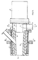
- Fig. 3 is an enlarged sectional view of the nozzle;
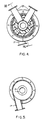
- Fig. 4 is a sectional view taken on line IV-IV of Fig. 3;
- Fig. 5 is a sectional view taken on line V-V of Fig. 3;
- Fig. 6 is an alternative embodiment of the cupola with a plasma fired nozzle shown in Fig. 3 disposed therein;
- Fig. 7 is an alternative embodiment of the nozzles shown in Fig. 2;
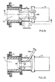
- Fig. 8 is a sectional view taken on line VIII-VIII of Fig. 7;
- Fig. 9 is an alternative embodiment of the nozzle shown in Fig. 7; and
- Fig. 10 is a sectional view taken on line X-X of Fig. 9.
- Referring now to the drawings in detail and in particular to Fig. 1 there is shown a portion of a furnace such as a cupola 1 with a plasma feed nozzle or tuyere 3 attached to a
side wall 5 thereof. The feed nozzle 3 comprises a tubular mixing chamber 7 lined with one or more layers of refractory 9 and encircled by a cooling jacket 11 through which a cooling fluid such as water is passed. The mixing chamber 7 has one end thereof open into the furnace 1. Aplasma torch 13 is disposed in the end of the mixing chamber 7 opposite the end opening into the furnace. Also disposed on the end of the mixing chamber opposite the end opening into the furnace is aplenum chamber 15. - Shroud air or process gas is introduced into the
plenum chamber 15 preferably through a shroudgas inlet nozzle 17 tangentially disposed with respect to theplenum chamber 15. Theplasma torch 13 such as the Marc II manufactured by Westinghouse Electric Corporation has aplasma nozzle 19 which extends through theplenum chamber 15 to provide a blast of flame-like superheated gas to the central portion of the mixing chambers 7. The temperature of the superheated gas entering the mixing chamber is generally in the range of 5500°C. - As shown in Fig. 1 there is a
refractory separator 21 disposed between the mixing chambers 7 and theplenum chamber 15 with a plurality ofinclined ports 23 disposed to introduce the shroud gas into the mixing chambers 7 in such a manner that the shroud gas swirls as it progresses axially through the mixing chamber 7 and the superheated gas from theplasma torch 13 is introduced along the axis of the mixing chamber 7 also swirling so that a gas temperature profile across the mixing chamber 7 is substantially hotter in the central portion thereof than adjacent therefractory walls 9. - A particulate
material feed nozzle 25 is disposed in fluid communication with the mixing chamber 7 and the axis thereof forms an acute angle with the axis of the mixing chamber 7 the angle being determined by the density, size, velocity and viscosity of the particulate material and transporting fluid which is adjusted to direct the influent feed material to the central portion of the mixing chamber 7 where the temperature is the hottest to rapidly raise the temperature of the influent particulate material. - As shown in Fig. 1 the mixing chamber 7 may extend at least partially through the refractory lining of the furnace or as shown in Fig. 2, the mixing chamber may abut the furnace's outer wall when there is an
opening 31 in the furnace wall andrefractory lining 5 which registers with the open end of themixing chamber 7a. - As shown in Figs. 3 and 6, the
mixing chamber 7b may be made with walls which taper inwardly toward the open end and there is no separator wall between theplenum chamber 15b and themixing chamber 7b, but there is anannular opening 35 between therefractory wall 9b and thenozzle 19 of theplasma torch 13. The tangentially disposedshroud gas nozzle 17 as shown best in Fig. 5 provides a swirling motion to the shroud gas entering theplenum chamber 15 producing a temperature profile across themixing chamber 7b which is substantially hotter in the central portion thereof than adjacent therefractory walls 9b. Therefractory walls 9b of themixing chamber 7b may be made of two or more refractory liners facilitating replacement of the inner lining which is subject to wear. - There may be a plurality of
feed material nozzles 25 as shown in Fig. 4, each of which is disposed to form a predetermined acute angle with the axis of themixing chamber 7b to direct the material to the central portion of the mixing chamber where the temperature is the hottest. - Figs. 7 and 8 show a
mixing chamber 7a,plenum chamber 15 andseparator 21 similar to those shown in Fig. 2 with the exception that thefeed nozzles 25a extend through theseparator 21 on either side of theplasma nozzle 19 generally parallel to the axis of the mixing chamber. - In Figs. 9 and 10, the
feed nozzles 25b enter through theseparator 21 generally above theplasma nozzle 19 and are generally parallel to the axis of the mixing chamber as they extend adjacent thereto. - The plasma feed nozzles hereinbefore described advantageously provide for the introduction of an extremely high temperature superheated gas in a confined space in which feed material can be rapidly heated and yet the refractory walls are relatively cool providing reasonable lengths of service.
Claims (8)
- A plasma feed nozzle (3) for use in a furnace (1), said plasma feed nozzle having- a plasma torch (13) for producing superheated gas at a temperature in the range of 5500°C,- a tubular mixing chamber (7) in fluid communication with said superheated gas, wherein the gas is hottest in the central portion of the mixing chamber (7) and wherein the mixing chamber has one end open to said furnace (1),- a shroud gas conduit (17) and means (15, 17, 21 and 23; 15b and 35) for introducing said shroud gas from said conduit (17) into said mixing chamber (7),- a particulate feed nozzle (25) in fluid communication with the mixing chamber (7) and a fluid jacket (11) encircling part of the mixing chamber (7),characterized by,- said tubular mixing chamber (7) beeing lined with a refractory material (9),- said particulate material feed nozzle (25) is connected with said mixing chamber (7) at an acute angle with the axis of the mixing chamber (7) disposed to introduce particulate material biased to the central portion of the mixing chamber (7) and the end open to the furnace (1)
- The plasma feed nozzle of claim 1 characterized in that the means for introducing shroud gas includes a plenum chamber (15) disposed on the end of the mixing chamber (7) opposite the end open to the furnace (1), the plenum chamber (15) being in fluid communication with the shroud gas conduit (17) and the mixing chamber (7).
- The plasma feed nozzle of claim 2, characterized by opening (35) between the mixing chamber (7) and the plenum chamber (15), and the plasma torch (13) is so disposed that a portion (19) thereof from which superheated gas is provided is aligned with the opening (35) and at least partially within the plenum chamber (15).
- The plasma feed nozzle of claim 3, characterized in that the portion (19) of the plasma torch (13) which supplies the superheated gas is disposed adjacent the opening (35) so as to provide an annular space between the portion of the plasma torch (13) which supplies the superheated gas and the opening (35) and the shroud gas conduit (17) is connected to the plenum chamber (15) tangentially whereby the shroud gas swirls in the plenum chamber (15) and as it passes through the annular opening into the mixing chamber (7).
- The plasma feed nozzle of claim 3, characterized in that a portion (19) of the plasma torch (13) from which the superheated gas is provided generally fills the opening (35) and there is a separator wall (21) with a plurality of ports (23) disposed radially outwardly of the opening and the ports (23) are oriented to cause the shroud gas to swirl as it enters the mixing chamber (7).
- The plasma feed nozzle of claims 4 or 5, characterized in that the tubular mixing chamber (7b) is tapered so that the end open into the furnace (1) is smaller than the end adjacent the plenum chamber (15b).
- The plasma feed nozzle of claim 1 characterized in that the particulate material feed (25) also introduces a carrier gas with the particulate material.
- The plasma feed nozzle of claim 7, characterized in that the particulate material feed nozzle (25a) is disposed to extend through said plenum chamber (15) and have a discharge portion which is generally parallel to the axis of the feed nozzle (3) and discharge into said mixing chamber (7a).
Applications Claiming Priority (2)
| Application Number | Priority Date | Filing Date | Title |
|---|---|---|---|
| US07/047,811 US4761793A (en) | 1987-05-08 | 1987-05-08 | Plasma fired feed nozzle |
| US47811 | 2002-01-15 |
Publications (2)
| Publication Number | Publication Date |
|---|---|
| EP0358711A1 EP0358711A1 (en) | 1990-03-21 |
| EP0358711B1 true EP0358711B1 (en) | 1993-08-11 |
Family
ID=21951110
Family Applications (1)
| Application Number | Title | Priority Date | Filing Date |
|---|---|---|---|
| EP88904867A Expired - Lifetime EP0358711B1 (en) | 1987-05-08 | 1988-05-05 | Plasma fired feed nozzle |
Country Status (9)
| Country | Link |
|---|---|
| US (1) | US4761793A (en) |
| EP (1) | EP0358711B1 (en) |
| JP (1) | JP2662589B2 (en) |
| KR (1) | KR960014438B1 (en) |
| BR (1) | BR8802181A (en) |
| CA (1) | CA1302518C (en) |
| DE (1) | DE3883232T2 (en) |
| MX (1) | MX164272B (en) |
| WO (1) | WO1988009109A1 (en) |
Cited By (1)
| Publication number | Priority date | Publication date | Assignee | Title |
|---|---|---|---|---|
| DE102008050184A1 (en) * | 2008-10-01 | 2010-04-15 | Technische Universität Chemnitz | Method and device for the thermal coating of surfaces, in particular high-speed flame spraying |
Families Citing this family (31)
| Publication number | Priority date | Publication date | Assignee | Title |
|---|---|---|---|---|
| FR2637442B1 (en) * | 1988-10-03 | 1990-11-02 | Aerospatiale | DEVICE FOR POSITIONING AND REMOVING A PLASMA TORCH ON AN APPARATUS OPERATING UNDER PRESSURE AND TEMPERATURE FORBIDDEN DIRECT INTERVENTION |
| DK720688D0 (en) * | 1988-12-23 | 1988-12-23 | Rockwool Int | METHOD AND APPARATUS FOR PREPARING A MELT FOR MINERAL FIBER PRODUCTION |
| US4998486A (en) * | 1989-04-27 | 1991-03-12 | Westinghouse Electric Corp. | Process and apparatus for treatment of excavated landfill material in a plasma fired cupola |
| US5090340A (en) * | 1991-08-02 | 1992-02-25 | Burgess Donald A | Plasma disintegration for waste material |
| US5637127A (en) * | 1995-12-01 | 1997-06-10 | Westinghouse Electric Corporation | Plasma vitrification of waste materials |
| BR9612101A (en) | 1995-12-20 | 1999-02-23 | Alcan Int Ltd | Plasma thermal reactor and method for wastewater treatment |
| RU2128408C1 (en) * | 1997-08-15 | 1999-03-27 | Акционерное общество "Гусиноозерская ГРЭС", Восточно-Сибирский государственный технологический университет | Plant for no-oil starting of pulverized-fuel boiler and illumination of flame pattern |
| US5960026A (en) * | 1997-09-09 | 1999-09-28 | The United States Of America As Represented By The Secretary Of The Navy | Organic waste disposal system |
| US8981250B2 (en) | 2001-07-16 | 2015-03-17 | Foret Plasma Labs, Llc | Apparatus for treating a substance with wave energy from plasma and an electrical Arc |
| US7857972B2 (en) | 2003-09-05 | 2010-12-28 | Foret Plasma Labs, Llc | Apparatus for treating liquids with wave energy from an electrical arc |
| US8764978B2 (en) | 2001-07-16 | 2014-07-01 | Foret Plasma Labs, Llc | System for treating a substance with wave energy from an electrical arc and a second source |
| US10188119B2 (en) | 2001-07-16 | 2019-01-29 | Foret Plasma Labs, Llc | Method for treating a substance with wave energy from plasma and an electrical arc |
| US7622693B2 (en) * | 2001-07-16 | 2009-11-24 | Foret Plasma Labs, Llc | Plasma whirl reactor apparatus and methods of use |
| US9481584B2 (en) | 2001-07-16 | 2016-11-01 | Foret Plasma Labs, Llc | System, method and apparatus for treating liquids with wave energy from plasma |
| US7632394B2 (en) * | 2007-05-29 | 2009-12-15 | Westinghouse Plasma Corporation | System and process for upgrading heavy hydrocarbons |
| CA2734630C (en) | 2008-05-15 | 2014-03-18 | Enersol Power Llc | Radiant heat flux enhanced organic material gasification system |
| US20090307974A1 (en) * | 2008-06-14 | 2009-12-17 | Dighe Shyam V | System and process for reduction of greenhouse gas and conversion of biomass |
| EP2344275A1 (en) * | 2008-10-03 | 2011-07-20 | Atlantic Hydrogen Inc. | Apparatus and method for effecting plasma-based reactions |
| US9222038B2 (en) * | 2009-02-11 | 2015-12-29 | Alter Nrg Corp. | Plasma gasification reactor |
| WO2010093553A2 (en) | 2009-02-11 | 2010-08-19 | Alter Nrg Corp | Plasma gasification reactor |
| US20100199556A1 (en) * | 2009-02-11 | 2010-08-12 | Dighe Shyam V | Plasma gasification reactor |
| US20100199557A1 (en) * | 2009-02-11 | 2010-08-12 | Dighe Shyam V | Plasma gasification reactor |
| KR101223237B1 (en) * | 2010-11-22 | 2013-01-17 | 한국에너지기술연구원 | Low carbon type of in-flight melting furnace by using fusion technology of plasma/gas for combustion, melting method therefor and material manufacturing method therefor |
| WO2012094743A1 (en) * | 2011-01-14 | 2012-07-19 | Atlantic Hydrogen Inc. | Plasma reactor and method of operation thereof |
| US9005320B2 (en) | 2011-02-05 | 2015-04-14 | Alter Nrg Corp. | Enhanced plasma gasifiers for producing syngas |
| CA2832895A1 (en) | 2011-04-13 | 2012-10-18 | Alter Nrg Corp. | Process and apparatus for treatment of incinerator ash |
| US8992656B2 (en) * | 2011-12-21 | 2015-03-31 | Praxair Technology, Inc. | Controllable solids injection |
| US9574770B2 (en) * | 2012-04-17 | 2017-02-21 | Alter Nrg Corp. | Start-up torch |
| US9095829B2 (en) * | 2012-08-16 | 2015-08-04 | Alter Nrg Corp. | Plasma fired feed nozzle |
| MX379490B (en) | 2012-12-11 | 2025-03-10 | Foret Plasma Labs Llc | HIGH TEMPERATURE COUNTERCURRENT VORTEX REACTOR SYSTEM, METHOD AND APPARATUS. |
| CN105189919B (en) | 2013-03-12 | 2017-12-01 | 弗雷特等离子实验室公司 | Apparatus and methods for sintering proppants |
Family Cites Families (6)
| Publication number | Priority date | Publication date | Assignee | Title |
|---|---|---|---|---|
| FR2217902A1 (en) * | 1973-02-12 | 1974-09-06 | Anvar | Plasma generator with reduced electrode wear - due to a coating of refractory oxide(s) on the electrode |
| US4002466A (en) * | 1975-11-03 | 1977-01-11 | Bethlehem Steel Corporation | Method of reducing ores |
| JPS5614121A (en) * | 1979-07-14 | 1981-02-10 | Omron Tateisi Electronics Co | Ultrasonic level meter with switch output |
| SE450898B (en) * | 1981-09-03 | 1987-08-10 | Skf Steel Eng Ab | SET FOR USING A PLASM MAGAZINE FOR SUPPLY OF HEAT ENERGY, AND DEVICE FOR IMPLEMENTATION OF THE SET |
| US4530101A (en) * | 1983-04-15 | 1985-07-16 | Westinghouse Electric Corp. | Electric arc fired cupola for remelting of metal chips |
| US4554435A (en) * | 1983-11-18 | 1985-11-19 | Westinghouse Electric Corp. | Electric arc heater having outlet gas admission |
-
1987
- 1987-05-08 US US07/047,811 patent/US4761793A/en not_active Expired - Fee Related
-
1988
- 1988-05-04 BR BR8802181A patent/BR8802181A/en not_active IP Right Cessation
- 1988-05-05 WO PCT/US1988/001543 patent/WO1988009109A1/en not_active Ceased
- 1988-05-05 EP EP88904867A patent/EP0358711B1/en not_active Expired - Lifetime
- 1988-05-05 JP JP63504582A patent/JP2662589B2/en not_active Expired - Fee Related
- 1988-05-05 DE DE88904867T patent/DE3883232T2/en not_active Expired - Fee Related
- 1988-05-06 MX MX11393A patent/MX164272B/en unknown
- 1988-05-06 CA CA000566180A patent/CA1302518C/en not_active Expired - Lifetime
- 1988-05-07 KR KR1019880005329A patent/KR960014438B1/en not_active Expired - Lifetime
Cited By (2)
| Publication number | Priority date | Publication date | Assignee | Title |
|---|---|---|---|---|
| DE102008050184A1 (en) * | 2008-10-01 | 2010-04-15 | Technische Universität Chemnitz | Method and device for the thermal coating of surfaces, in particular high-speed flame spraying |
| DE102008050184B4 (en) * | 2008-10-01 | 2011-04-21 | Technische Universität Chemnitz | Method and apparatus for high velocity flame spraying |
Also Published As
| Publication number | Publication date |
|---|---|
| JPH02504066A (en) | 1990-11-22 |
| US4761793A (en) | 1988-08-02 |
| MX164272B (en) | 1992-07-29 |
| KR960014438B1 (en) | 1996-10-15 |
| BR8802181A (en) | 1988-12-06 |
| DE3883232D1 (en) | 1993-09-16 |
| EP0358711A1 (en) | 1990-03-21 |
| WO1988009109A1 (en) | 1988-11-17 |
| DE3883232T2 (en) | 1994-01-05 |
| KR880014845A (en) | 1988-12-24 |
| JP2662589B2 (en) | 1997-10-15 |
| CA1302518C (en) | 1992-06-02 |
Similar Documents
| Publication | Publication Date | Title |
|---|---|---|
| US4761793A (en) | Plasma fired feed nozzle | |
| KR100868545B1 (en) | Gas injection lance | |
| KR20000068565A (en) | Method and apparatus for cooling exhaust gas from bypass of kiln | |
| US4665842A (en) | Apparatus for producing ignitable solids-gas suspensions | |
| US4039277A (en) | Apparatus for calcining powder materials | |
| US3932117A (en) | Method of burning or sintering fine-grain material | |
| US4276020A (en) | Method for heating powder material and apparatus for carrying out said method | |
| CN104718018A (en) | Plasma ignition feed nozzle | |
| KR20030024903A (en) | Method and plant for manufacturing cement clinker | |
| EP0151683B1 (en) | Cooling system for post-mixed burner | |
| EP0076538B1 (en) | Liquid cooled lance for blowing oxygen onto a steel bath | |
| US3603568A (en) | Apparatus for heat treatment of fine material | |
| US4414673A (en) | Plasma melting furnace | |
| AU730499B2 (en) | Furnace having toroidal fluid flow heating zone | |
| US5397109A (en) | Reduced emissions metal melting furnace | |
| CS205038B2 (en) | Tuyere incooled by water | |
| US4652725A (en) | Method and apparatus for heating a first gas flow with a second gas flow | |
| FI60610C (en) | SAETT ATT BLANDA EN HET UGNSGAS MED EN ANNAN GAS FOERE AVLAEGSNING AV UGNSGASEN FRAON UGNEN SAMT HUV DOERFOER | |
| SU1771486A3 (en) | BLAST FURNACE FURNACE | |
| WO1997002365A1 (en) | Device for after-burning combustible components of the atmosphere in metallurgical smelting vessels | |
| SU1384902A1 (en) | Vertical furnace for heat treatment of loose material | |
| CA1235863A (en) | Steam cooled spout | |
| JPH0132176B2 (en) | ||
| JPH072552A (en) | Method and apparatus for circulating alkali-containing circulating gas from the combustion zone of a vertical furnace, in particular an annular vertical furnace | |
| US4615675A (en) | Furnace channel heating method and apparatus |
Legal Events
| Date | Code | Title | Description |
|---|---|---|---|
| PUAI | Public reference made under article 153(3) epc to a published international application that has entered the european phase |
Free format text: ORIGINAL CODE: 0009012 |
|
| 17P | Request for examination filed |
Effective date: 19891020 |
|
| AK | Designated contracting states |
Kind code of ref document: A1 Designated state(s): DE FR GB NL SE |
|
| 17Q | First examination report despatched |
Effective date: 19920226 |
|
| GRAA | (expected) grant |
Free format text: ORIGINAL CODE: 0009210 |
|
| AK | Designated contracting states |
Kind code of ref document: B1 Designated state(s): DE FR GB NL SE |
|
| REF | Corresponds to: |
Ref document number: 3883232 Country of ref document: DE Date of ref document: 19930916 |
|
| ET | Fr: translation filed | ||
| PLBE | No opposition filed within time limit |
Free format text: ORIGINAL CODE: 0009261 |
|
| STAA | Information on the status of an ep patent application or granted ep patent |
Free format text: STATUS: NO OPPOSITION FILED WITHIN TIME LIMIT |
|
| 26N | No opposition filed | ||
| EAL | Se: european patent in force in sweden |
Ref document number: 88904867.4 |
|
| PGFP | Annual fee paid to national office [announced via postgrant information from national office to epo] |
Ref country code: NL Payment date: 19990322 Year of fee payment: 12 |
|
| PGFP | Annual fee paid to national office [announced via postgrant information from national office to epo] |
Ref country code: SE Payment date: 19990504 Year of fee payment: 12 |
|
| PG25 | Lapsed in a contracting state [announced via postgrant information from national office to epo] |
Ref country code: SE Free format text: LAPSE BECAUSE OF NON-PAYMENT OF DUE FEES Effective date: 20000506 |
|
| PG25 | Lapsed in a contracting state [announced via postgrant information from national office to epo] |
Ref country code: NL Free format text: LAPSE BECAUSE OF NON-PAYMENT OF DUE FEES Effective date: 20001201 |
|
| EUG | Se: european patent has lapsed |
Ref document number: 88904867.4 |
|
| NLV4 | Nl: lapsed or anulled due to non-payment of the annual fee |
Effective date: 20001201 |
|
| REG | Reference to a national code |
Ref country code: GB Ref legal event code: IF02 |
|
| PGFP | Annual fee paid to national office [announced via postgrant information from national office to epo] |
Ref country code: GB Payment date: 20030401 Year of fee payment: 16 |
|
| PGFP | Annual fee paid to national office [announced via postgrant information from national office to epo] |
Ref country code: FR Payment date: 20030505 Year of fee payment: 16 |
|
| PG25 | Lapsed in a contracting state [announced via postgrant information from national office to epo] |
Ref country code: GB Free format text: LAPSE BECAUSE OF NON-PAYMENT OF DUE FEES Effective date: 20040505 |
|
| PGFP | Annual fee paid to national office [announced via postgrant information from national office to epo] |
Ref country code: DE Payment date: 20040528 Year of fee payment: 17 |
|
| GBPC | Gb: european patent ceased through non-payment of renewal fee |
Effective date: 20040505 |
|
| PG25 | Lapsed in a contracting state [announced via postgrant information from national office to epo] |
Ref country code: FR Free format text: LAPSE BECAUSE OF NON-PAYMENT OF DUE FEES Effective date: 20050131 |
|
| REG | Reference to a national code |
Ref country code: FR Ref legal event code: ST |
|
| PG25 | Lapsed in a contracting state [announced via postgrant information from national office to epo] |
Ref country code: DE Free format text: LAPSE BECAUSE OF NON-PAYMENT OF DUE FEES Effective date: 20051201 |