EP0357441A1 - Unterwasser-Kommunikationsvorrichtungen - Google Patents
Unterwasser-Kommunikationsvorrichtungen Download PDFInfo
- Publication number
- EP0357441A1 EP0357441A1 EP89308857A EP89308857A EP0357441A1 EP 0357441 A1 EP0357441 A1 EP 0357441A1 EP 89308857 A EP89308857 A EP 89308857A EP 89308857 A EP89308857 A EP 89308857A EP 0357441 A1 EP0357441 A1 EP 0357441A1
- Authority
- EP
- European Patent Office
- Prior art keywords
- sonar
- beacon
- enclosure
- beacons
- signals
- Prior art date
- Legal status (The legal status is an assumption and is not a legal conclusion. Google has not performed a legal analysis and makes no representation as to the accuracy of the status listed.)
- Granted
Links
Images

Classifications
-
- H—ELECTRICITY
- H01—ELECTRIC ELEMENTS
- H01Q—ANTENNAS, i.e. RADIO AERIALS
- H01Q1/00—Details of, or arrangements associated with, antennas
- H01Q1/04—Adaptation for subterranean or subaqueous use
Definitions
- This invention relates to underwater communication devices.
- a major problem which is experienced by Hunter type weapons of the anti-submarine variety is the limited range of acoustic-sonar detectors and hence the short range at which a target can be identified.
- This drawback can be overcome if sensing devices are positioned well away from, and peripheral to, the weapons. Signals received by such sensing devices could be analysed, a vessel identified by comparison with a library of voice prints, and a coded message transmitted to a weapon, all well in advance of the approach of a possible target. Alternatively, the voice print could be broadcast in its entirety. In either event, the response time available to the weapon system could be significantly enhanced.
- sensors and weapons could be positioned on the sea bed in such a manner as to form not only a "safe haven” for friendly vessels, but also as a trap for enemy shipping which tried to penetrate the safe area. It would be particularly useful for friendly vessels which believe they may be being shadowed/followed, to run through a series of underwater communication devices which could detect and disseminate information on the shadowing vessel and prepare weapon systems to destroy it.
- Such weapon systems could be of a type described or illustrated in our European Patent Application No.83306517.0.
- This invention provides an underwater communications device comprising an enclosure, means to anchor the enclosure to the sea bed, sonar listening equipment in the enclosure for receiving sonar signals from the surrounding water, a plurality of communications beacons enclosed in individual buoyant containers, means for releasably holding the beacon in the enclosure and means for releasing a beacon from the enclosure in response to receipt of a sonar signal by said sonar receiving means to allow the beacons to surface and to transmit a signal pursuant to the receipt of said sonar signal.
- the sonar receiving apparatus may include means to store different sonar signals emitted by different surface or underwater vessels whether hostile or friendly, means to receive and compare a sonar signal with said stored sonar signals and means to initiate release of a beacon in response to any sonar signal identified as being that of a hostile vessel to transmit a signal indicating the presence of a hostile vessel.
- the sonar receiving apparatus may be arranged to supply information to the beacon including the identity of the vessel detected to be transmitted by said beacon after release of the beacon from the enclosure and on reaching the surface.
- the beacons may embody radio transmitters for transmitting radio signals on surfacing indicating the detection of a "hostile" vessel.
- the apparatus may be provided with means for communicating with one or more remote weapon systems for activating the weapon systems to be used against a target detected by the sonar equipment.
- the enclosure may have an upper part containing the sonar equipment and said beacons and a lower part having means to bury the lower part in the sea bed.
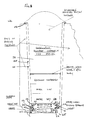
- an underwater communication device comprising a watertight elongate vertically extending container 10 which is intended to be partially or wholly buried in the sea bed 11.
- the upper part of the container 10 contains a first, inner canister 12 in which a plurality of individually releasable communication beacons 13 are housed and the lower part of the container houses a second canister 14 containing a burying mechanism for the container 10.
- the outer container 10 is, as indicated above, of elongate form and generally cylindrical cross-section.
- the container is buried or partially buried within the sea bed 11 as illustrated in the drawing to minimise the risk of the device being detected or damaged.
- the container has self-burying means comprising, firstly a centrifugal pump 15 for removing sand or silt from under the bottom end of the container; secondly a spiral or helical agitator/auger 16 for loosening the material on the sea bed and thirdly a high pressure pump 17 for pumping sea water to nozzles 18 disposed around the periphery of the lower end of the container 10 and for loosening sand or silt under the container.
- the centrifugal pump 15 is driven by an electric drive motor 19 through a gear train 20, the motor being powered by batteries 21.
- This pump sucks up sand and silt from the sea bed, as indicated by chain lines 22, and forces it radially outwardly to the lower end of an annular region 23 between the outer container 10 and the inner canisters 12 and 14.
- the sand and silt are forced upwardly through this annular region to be expelled as indicated by arrows 24 at the upper end of the container 10.
- the agitator/auger 16 is driven from the drive shaft of the pump 15. This shaft also drives a high pressure pump 17.
- the device is laid in position by dropping it into the sea and it is so constructed that when released in water, it falls with the burying mechanism downwards so this end settles on the sea bed.
- the container would be substantially wholly buried to minimise the risk of detection by underwater search equipment or accidental damage by equipment moving along the sea bed. Sand or silt may get washed over the container by the sea with the result that the container may be completely covered.
- Control of the self-burial means may be effected using appropriate sensors.
- a first sensor 25 to detect initial contact with the sea bed and initiate operation of the motor 19 is mounted at the lower end of the container 10 and a second sensor 26 is mounted adjacent the upper end of container 10 to detect burial of the container to the required depth.
- the upper canister 13 is formed with a central vertically extending housing 30 the lower part of which contains a control assembly 31 including a sonar receiver, a data processing device and an interface device for interfacing the sonar receiver with the radio beacons 13.
- the upper part of the housing 30 is an aerial housing 32 containing an extendible sonar aerial mechanism 33 which extends automatically once the container is fully buried as detected by the sensor 26.
- each beacon 38 forms a piston in the lower end of its tube 35 and the lower end of the tube is connected by a passage 46 to a pneumatically or hydraulically operated ram 47 containing a vertically operating piston assembly 48.
- the cylinder 47 is connected by a lateral passage 49 through a non-return inlet valve 50 to the aforesaid annular passage 23 to receive a charge of water therefrom when the ram 48 is returned.
- Ram 48 is advanced to displace water from the cylinder 47 through passage 46 into the lower end of tube 35 to force the beacon 38 contained in the tube upwardly fracturing the watertight seal 37 to project out of the tube. Once the seal 37 has been fractured, the tube 35 will flood and the beacon will float upwardly out of the tube to the surface under the influence of its own positive buoyancy. Operation of the hydraulic pneumatic rams connected to piston assemblies 48 is effected by a rotary switch construction (not shown) triggered by a signal from the control assembly 31 described above.
- the seals 37 could be frangible or held in position with vacuum differential on an "O" ring and and solenoid controlled valves may be provided connecting the tubes to the annular chamber to flood the tube of a beacon to be deployed. Once the tube has been flooded to bring the tube into equilibrium, the beacons could be driven out with hydro-static pressure or a gas charge such as that provided by firing a pyro-technic type cartridge could be utilised.
- the control assembly 31 of the underwater communication device receives sonar signals from vessels passing within range of the device. It is well known that each vessel has its own individual noise pattern and the control assembly has a memory in which the noise patterns of all known friendly and enemy vessels are recorded.
- the control assembly has facilities for analysing received sonar signals to determine whether they are of friendly or enemy vessels and, if of enemy vessels, to initiate the firing of one of the radio beacons 38 to the surface to transmit a signal by radio warning that an enemy vessel has been detected.
- the radio beacons broadcast coded messages on surfacing and, following a set period of broadcasting and after acknowledgement that a message has been received, a programme to self-destruct the device is initiated automatically.
- the control assembly may also be arranged to cause the radio to transmit a signal identifying the vessel detected.
- each of the tubes 35 tapers towards its lower end and the bodies of the beacons 38 taper in a corresponding manner and are dimensioned to provide a narrow gap 55 between the outer wall of the beacon 38 and the encircling wall of the tube 35.
- annular resilient "O" ring seals 56 are mounted around the upper open ends of the tubes 35 and each of the beacons 38 has an annular rim adjacent its upper end to engage the encircling seal 56 of the respective tube 35 in which the beacon is housed.
- each beacon 38 is formed with an annular skirt 58 having an inner annular rib 59.
- a plurality of latches 60 are mounted on pivots 61 around the lower end of the tube 35 to project into the skirt 58 of the beacon and are spring loaded by tension springs 62 to engage with the rib 59 and retain the beacon in the tube. The latches are retracted to release the beacon by solenoids indicated at 63.
- a heavy compression spring 64 is disposed in the underside of the beacon 38 and the bottom wall 65 of the tube 35 to assist in spacing the beacon from the tube when the latches 60 have been released.
- the beacon could, equally, be discharged with the assistance of a gas charge or hydraulic pressure applied to the underside of the beacon.
- each container tube 35 housing the beacons is initially filled with a nitrogen atmosphere to minimise corrosion of the beacons and their release mechanisms when the communication device is installed on the sea bed. There will be a considerable pressure differential depending on the depth of water in which the device is located tending to hold the beacons in the container tubes.
- each container tube has a solenoid controlled valve (not shown) connecting the tube to the encircling annular region 23 between the inner and outer canisters to allow water to bleed into the tubes 35 when the solenoid controlled valve is open. Both the solenoid controlled valves and the solenoid controlled latches holding the beacons in the tubes are triggered by said rotary switch from the control assembly when a beacon is to be released as described above.
- the "O" ring seals 56 are omitted as are the solenoid controlled valves for the tubes 35 and the tubes are allowed to flood with sea water on immersion of the device in the sea.
- the solenoid controlled latches holding the beacons in place in the tubes are constructed and arranged so as not to be affected by sea water present in the tubes.
- the container of the beacon itself is constructed to serve as the transmitting aerial for the beacon, that is the dome of the beacon embodies the aerial.
- the dome could also be provided with a gas-filled balloon which is deployed automatically once the beacon reaches the surface of the sea to enable a radio signal to be transmitted over a greater range.
Landscapes
- Measurement Of Velocity Or Position Using Acoustic Or Ultrasonic Waves (AREA)
Applications Claiming Priority (2)
| Application Number | Priority Date | Filing Date | Title |
|---|---|---|---|
| GB8820719A GB2222805B (en) | 1988-09-02 | 1988-09-02 | Improvements in or relating to underwater communication devices |
| GB8820719 | 1988-09-02 |
Publications (2)
| Publication Number | Publication Date |
|---|---|
| EP0357441A1 true EP0357441A1 (de) | 1990-03-07 |
| EP0357441B1 EP0357441B1 (de) | 1993-11-10 |
Family
ID=10643043
Family Applications (1)
| Application Number | Title | Priority Date | Filing Date |
|---|---|---|---|
| EP19890308857 Expired - Lifetime EP0357441B1 (de) | 1988-09-02 | 1989-09-01 | Unterwasser-Kommunikationsvorrichtungen |
Country Status (4)
| Country | Link |
|---|---|
| EP (1) | EP0357441B1 (de) |
| DE (1) | DE68910620T2 (de) |
| DK (1) | DK436489A (de) |
| GB (1) | GB2222805B (de) |
Cited By (4)
| Publication number | Priority date | Publication date | Assignee | Title |
|---|---|---|---|---|
| US6130642A (en) * | 1997-03-04 | 2000-10-10 | The United States Of America As Represented By The Secretary Of The Navy | Method and system to improve GPS navigation |
| EP1092937A3 (de) * | 1999-10-13 | 2002-04-03 | Lawborough Consultants Limited | Behälter zur Installation im Meeresboden |
| GB2377412A (en) * | 2000-11-03 | 2003-01-15 | Lawborough Consultants Ltd | Support vessel for self-burying mines |
| RU184783U1 (ru) * | 2018-01-31 | 2018-11-08 | Федеральное Государственное Казенное Военное Образовательное Учреждение Высшего Образования "Тихоокеанское Высшее Военно-Морское Училище Имени С.О. Макарова" Министерства Обороны Российской Федерации (Г. Владивосток) | Радиогидроакустический буй на микроконтроллере |
Citations (6)
| Publication number | Priority date | Publication date | Assignee | Title |
|---|---|---|---|---|
| US3460058A (en) * | 1960-10-25 | 1969-08-05 | Itt | Radio sonobuoy |
| DE2209544A1 (de) * | 1972-02-29 | 1973-09-13 | Dynamit Nobel Ag | Signaleinrichtung fuer schiffe in seenot |
| GB1534852A (en) * | 1967-11-23 | 1978-12-06 | Ultra Electronics Ltd | Underwater detection equipment |
| US4189786A (en) * | 1962-06-29 | 1980-02-19 | Adler Ronald E | Radio buoy assembly |
| EP0110554A2 (de) * | 1982-10-28 | 1984-06-13 | Underwater Storage Limited | Unterwasser-Waffensysteme |
| WO1986004873A1 (en) * | 1985-02-19 | 1986-08-28 | Cochrane Subsea Acoustics, Inc. | Subsea acoustic relocation system |
Family Cites Families (1)
| Publication number | Priority date | Publication date | Assignee | Title |
|---|---|---|---|---|
| GB2148798B (en) * | 1983-08-15 | 1987-06-03 | Cochrane Subsea Acoustics Inc | Subsea accoustic relocation system |
-
1988
- 1988-09-02 GB GB8820719A patent/GB2222805B/en not_active Expired - Fee Related
-
1989
- 1989-09-01 DE DE1989610620 patent/DE68910620T2/de not_active Expired - Lifetime
- 1989-09-01 EP EP19890308857 patent/EP0357441B1/de not_active Expired - Lifetime
- 1989-09-04 DK DK436489A patent/DK436489A/da not_active Application Discontinuation
Patent Citations (6)
| Publication number | Priority date | Publication date | Assignee | Title |
|---|---|---|---|---|
| US3460058A (en) * | 1960-10-25 | 1969-08-05 | Itt | Radio sonobuoy |
| US4189786A (en) * | 1962-06-29 | 1980-02-19 | Adler Ronald E | Radio buoy assembly |
| GB1534852A (en) * | 1967-11-23 | 1978-12-06 | Ultra Electronics Ltd | Underwater detection equipment |
| DE2209544A1 (de) * | 1972-02-29 | 1973-09-13 | Dynamit Nobel Ag | Signaleinrichtung fuer schiffe in seenot |
| EP0110554A2 (de) * | 1982-10-28 | 1984-06-13 | Underwater Storage Limited | Unterwasser-Waffensysteme |
| WO1986004873A1 (en) * | 1985-02-19 | 1986-08-28 | Cochrane Subsea Acoustics, Inc. | Subsea acoustic relocation system |
Non-Patent Citations (1)
| Title |
|---|
| ELECTRICAL/ELECTRONIC POWER & CONTROL, PRODUCT ENGINEERING, vol. 40, no. 12, 16th June 1969, pages 94-95; "Coded sounds in the sea direct underwater work more reliably" * |
Cited By (4)
| Publication number | Priority date | Publication date | Assignee | Title |
|---|---|---|---|---|
| US6130642A (en) * | 1997-03-04 | 2000-10-10 | The United States Of America As Represented By The Secretary Of The Navy | Method and system to improve GPS navigation |
| EP1092937A3 (de) * | 1999-10-13 | 2002-04-03 | Lawborough Consultants Limited | Behälter zur Installation im Meeresboden |
| GB2377412A (en) * | 2000-11-03 | 2003-01-15 | Lawborough Consultants Ltd | Support vessel for self-burying mines |
| RU184783U1 (ru) * | 2018-01-31 | 2018-11-08 | Федеральное Государственное Казенное Военное Образовательное Учреждение Высшего Образования "Тихоокеанское Высшее Военно-Морское Училище Имени С.О. Макарова" Министерства Обороны Российской Федерации (Г. Владивосток) | Радиогидроакустический буй на микроконтроллере |
Also Published As
| Publication number | Publication date |
|---|---|
| DE68910620D1 (de) | 1993-12-16 |
| DK436489A (da) | 1990-03-03 |
| DE68910620T2 (de) | 1994-03-03 |
| DK436489D0 (da) | 1989-09-04 |
| GB8820719D0 (en) | 1989-03-30 |
| GB2222805A (en) | 1990-03-21 |
| EP0357441B1 (de) | 1993-11-10 |
| GB2222805B (en) | 1992-04-29 |
Similar Documents
| Publication | Publication Date | Title |
|---|---|---|
| EP2190743B1 (de) | Verfahren und vorrichtung zum einsatz auf see | |
| US4692906A (en) | Ocean bottom seisometer | |
| US5170005A (en) | System for underwater storage and launching of rockets | |
| US7946241B2 (en) | Methods and apparatus for marine deployment | |
| RU2759033C2 (ru) | Автономная локационная система летательного аппарата | |
| EP2055629A2 (de) | Externe Rettungs- und Bergungsvorrichtungen und -verfahren für Unterwasserfahrzeuge | |
| CA2845265C (en) | Communication buoy and method of deployment | |
| US5277117A (en) | Underwater mine countermeasure warfare system | |
| US4141295A (en) | Actuation mine simulator | |
| US4586421A (en) | Underwater weapon systems | |
| US5224074A (en) | Sonobuoy for forming virtual vertical sensing arrays | |
| US4281427A (en) | Warning and signalling device, especially for maritime purposes | |
| US20040059476A1 (en) | Deep sea data retrieval apparatus and system | |
| EP0357441B1 (de) | Unterwasser-Kommunikationsvorrichtungen | |
| US6220168B1 (en) | Underwater intelligence gathering weapon system | |
| US4395952A (en) | Underwater weapon systems | |
| US6371003B1 (en) | Enclosures for installation on the seabed | |
| US5339288A (en) | Underwater sound source with remote controlled actuator | |
| EP0785886A1 (de) | Einmal unterwasserfahrzeug | |
| GB2048439A (en) | Improvements in or relating to underwater weapons | |
| US5033354A (en) | Deep operating monitor and destruct device | |
| US5386793A (en) | Line handling apparatus | |
| RU2309871C2 (ru) | Двухмодульная подводная лодка с аварийно-спасательной системой, оснащенная оперативно-тактическим комплексом | |
| RU2819811C1 (ru) | Мобильная система охраны морского района | |
| EP0053210B1 (de) | Unterwasserwaffe |
Legal Events
| Date | Code | Title | Description |
|---|---|---|---|
| PUAI | Public reference made under article 153(3) epc to a published international application that has entered the european phase |
Free format text: ORIGINAL CODE: 0009012 |
|
| AK | Designated contracting states |
Kind code of ref document: A1 Designated state(s): DE FR SE |
|
| 17P | Request for examination filed |
Effective date: 19900403 |
|
| 17Q | First examination report despatched |
Effective date: 19921016 |
|
| GRAA | (expected) grant |
Free format text: ORIGINAL CODE: 0009210 |
|
| AK | Designated contracting states |
Kind code of ref document: B1 Designated state(s): DE FR SE |
|
| REF | Corresponds to: |
Ref document number: 68910620 Country of ref document: DE Date of ref document: 19931216 |
|
| ET | Fr: translation filed | ||
| PLBE | No opposition filed within time limit |
Free format text: ORIGINAL CODE: 0009261 |
|
| STAA | Information on the status of an ep patent application or granted ep patent |
Free format text: STATUS: NO OPPOSITION FILED WITHIN TIME LIMIT |
|
| 26N | No opposition filed | ||
| EAL | Se: european patent in force in sweden |
Ref document number: 89308857.5 |
|
| PGFP | Annual fee paid to national office [announced via postgrant information from national office to epo] |
Ref country code: DE Payment date: 20060331 Year of fee payment: 17 |
|
| PG25 | Lapsed in a contracting state [announced via postgrant information from national office to epo] |
Ref country code: FR Free format text: LAPSE BECAUSE OF NON-PAYMENT OF DUE FEES Effective date: 20060531 |
|
| REG | Reference to a national code |
Ref country code: FR Ref legal event code: ST Effective date: 20060531 |
|
| PGFP | Annual fee paid to national office [announced via postgrant information from national office to epo] |
Ref country code: FR Payment date: 20060817 Year of fee payment: 18 |
|
| REG | Reference to a national code |
Ref country code: FR Ref legal event code: D3 |
|
| PG25 | Lapsed in a contracting state [announced via postgrant information from national office to epo] |
Ref country code: DE Free format text: LAPSE BECAUSE OF NON-PAYMENT OF DUE FEES Effective date: 20070403 |
|
| PGFP | Annual fee paid to national office [announced via postgrant information from national office to epo] |
Ref country code: SE Payment date: 20060907 Year of fee payment: 18 |
|
| PG25 | Lapsed in a contracting state [announced via postgrant information from national office to epo] |
Ref country code: SE Free format text: LAPSE BECAUSE OF NON-PAYMENT OF DUE FEES Effective date: 20070902 |
|
| EUG | Se: european patent has lapsed | ||
| REG | Reference to a national code |
Ref country code: FR Ref legal event code: ST Effective date: 20080531 |