EP0357227A1 - Rotary nozzle - Google Patents
Rotary nozzle Download PDFInfo
- Publication number
- EP0357227A1 EP0357227A1 EP89307736A EP89307736A EP0357227A1 EP 0357227 A1 EP0357227 A1 EP 0357227A1 EP 89307736 A EP89307736 A EP 89307736A EP 89307736 A EP89307736 A EP 89307736A EP 0357227 A1 EP0357227 A1 EP 0357227A1
- Authority
- EP
- European Patent Office
- Prior art keywords
- rotor
- detent
- turning
- actuator
- rotary nozzle
- Prior art date
- Legal status (The legal status is an assumption and is not a legal conclusion. Google has not performed a legal analysis and makes no representation as to the accuracy of the status listed.)
- Granted
Links
- 239000011449 brick Substances 0.000 claims abstract description 25
- 229910000831 Steel Inorganic materials 0.000 claims abstract description 17
- 239000010959 steel Substances 0.000 claims abstract description 17
- 238000010276 construction Methods 0.000 claims description 7
- 230000002093 peripheral effect Effects 0.000 claims description 3
- 230000000694 effects Effects 0.000 abstract description 4
- 239000003638 chemical reducing agent Substances 0.000 abstract 2
- 230000004048 modification Effects 0.000 description 3
- 238000012986 modification Methods 0.000 description 3
- 238000005192 partition Methods 0.000 description 3
- 230000003247 decreasing effect Effects 0.000 description 2
- 238000007689 inspection Methods 0.000 description 2
- 238000012423 maintenance Methods 0.000 description 2
- 239000000463 material Substances 0.000 description 2
- 230000007812 deficiency Effects 0.000 description 1
- 230000009977 dual effect Effects 0.000 description 1
Images


Classifications
-
- B—PERFORMING OPERATIONS; TRANSPORTING
- B22—CASTING; POWDER METALLURGY
- B22D—CASTING OF METALS; CASTING OF OTHER SUBSTANCES BY THE SAME PROCESSES OR DEVICES
- B22D11/00—Continuous casting of metals, i.e. casting in indefinite lengths
- B22D11/10—Supplying or treating molten metal
-
- B—PERFORMING OPERATIONS; TRANSPORTING
- B22—CASTING; POWDER METALLURGY
- B22D—CASTING OF METALS; CASTING OF OTHER SUBSTANCES BY THE SAME PROCESSES OR DEVICES
- B22D41/00—Casting melt-holding vessels, e.g. ladles, tundishes, cups or the like
- B22D41/14—Closures
- B22D41/22—Closures sliding-gate type, i.e. having a fixed plate and a movable plate in sliding contact with each other for selective registry of their openings
- B22D41/26—Closures sliding-gate type, i.e. having a fixed plate and a movable plate in sliding contact with each other for selective registry of their openings characterised by a rotatively movable plate
Definitions
- the present invention relates to a rotary nozzle of the type which is attached to the bottom of a molten steel vessel, e.g., a laddle or tundish so that a sliding plate brick is rotated and the opening of a nozzle bore of a fixed plate brick is adjusted thereby controlling the pouring rate of molten steel, and more particularly the invention relates to a turning apparatus for a rotor which holds the sliding plate brick.
- Rotary nozzles have been used widely with laddles for receiving the molten steel tapped from a converter or the like to transport or to pour the molten steel into molds, tundishes for receiving the molten steel from a laddle to pour the molten steel into molds and the like.
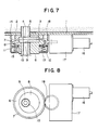
- Fig. 7 is a longitudinal sectional view showing schematically an example of a conventional rotary nozzle
- Fig. 8 is a bottom view of Fig. 7 with a part thereof being omitted.
- numeral 1 designates a shim plate mounted to the bottom of a laddle, tundish or the like
- 2 a base member attached to the shim plate and formed with a recess for mounting a fixed plate brick 3 therein and an opening into which a top nozzle 5 is fitted.
- Numeral 6 designates a rotor rotatably arranged on a movable member 11 through a ball bearing 12, formed with a recess in which a sliding plate brick 8 is mounted and an opening into which a bottom nozzle 10 is fitted and provided with a gear 7 on its upper outer periphery thereof.
- Numeral 13 designates a frame adapted to accommodate the rotor 6 and pivotably attached to the shim plate 1 by a hinge 14. It is to be noted that although not shown, the opposite side to the hinge 14 is secured to the shim member 1 with bolts, levers or the like.
- Numeral 15 designates springs mounted between the movable member 11 and the frame 13 and they are adapted to press the rotor 6 upward and force the sliding surface of the sliding plate brick 8 into close contact with the fixed plate brick 3.
- Numeral 16 designates a motor, 17 a reduction gear, and 18 the final-stage gear of the reduction gear 17 which is in mesh with the gear 7 of the rotor 6.
- the nozzle bores of the top nozzle 5, the fixed plate brick 3, the sliding plate brick 8 and the bottom nozzle 10 are located on the same center, and the nozzle bore 9 of the sliding plate brick 8 is in a wide-open position relative to the nozzle bore 4 of the fixed plate brick 3. Therefore, the molten steel in the laddle or the like is poured into a tundish or the like in the maximum amount.
- the motor 16 is operated so that the rotation reduced by the reduction gear 17 is transmitted to the rotor 6 through the gears 18 and 17, thereby rotating the rotor 6 through a desired angle. When this occurs, the opening of the nozzle bores 4 and 9 is adjusted to control the pouring rate of the molten steel.
- Rotary nozzles of this type have been recently used in large numbers owing to a number of advantages that the maintenance and inspection are easy, that the damages on the surfaces of the fixed plate brick 3 and the sliding plate brick 8 can be confirmed with the naked eye and they can also be replaced easily and so on.
- the driving unit for the rotor 6, that is, the motor 16 and the reduction gear 17 which are attached to the bottom of the laddle or the like are extremely large in size and weight thus making it inconvenient to handle.
- the present invention has been made to overcome the foregoing deficiencies and it is an object of the invention to provide a rotary nozzle equipped with a rotor driving unit which is small in size and light in weight.
- a rotary nozzle including a rotor formed with a plurality of notched engaging portions at equal intervals on its outer periphery, a turning member rotatably arranged along the rotor and including detent means adapted to engage with the engaging portions and a locking mechanism for bringing the detent means into and out of engagement with the engaging portions, and a hydraulic cylinder having an actuator connected to the turning member.
- a gear is formed on the outer periphery of the turning member, and the hydraulic cylinder is replaced with a rocking actuator whose output side is connected to a gear which in turn is connected to the gear of the turning member.
- a belt member having a lining on its inner surface is arranged on the outer periphery of the rotor in a manner that the ends of the belt member are attached to a connecting member having a function of tightening and loosing the belt member, and the connecting member is connected to the actuator of the hydraulic cylinder.
- Fig. 1 is a longitudinal sectional view of an embodiment of the present invention
- Fig. 2 is a sectional view taken along the line A-A of Fig. 1.
- Numeral 21 designates a ring portion provided on the upper outer periphery of a rotor 6 to be integral therewith and a plurality of notched engaging portions 22a to 22n are formed on its outer periphery at equal intervals (at intervals of 30 o in this embodiment).
- Numeral 23 designates a shuttle ring having a C sectional shape and formed on its inner periphery with a groove 24 rotatably loose-fitted on the ring portion 21 of the rotor 6.
- the shuttle ring 23 includes an arm 25 and an outwardly projecting convex portion 26 on the opposite side to the arm 25.
- Numeral 42 designates a hydraulic cylinder attached by a support arm 41 to one side of the convex portion 26 of the shuttle ring 23 (in this embodiment the convex portion 26 is arranged over an extent of about 60 o corresponding to the intervals of two of the engaging portions 22a to 22n).
- Numeral 44 designates a substantially Z-shaped lock member formed at its one end with a detent portion 45 for selectively engaging with the engaging portions 22a to 22n formed on the ring portion 21 and it is inserted into a slot 26a formed in the convex portion 26 with its substantially central portion being rotatably pivoted by a pin 46.
- the other end of the lock member 44 is pivotably connected to an actuator 43 of the hydraulic cylinder 42. It is to be noted that these component parts form a locking mechanism 40 for the rotor 6.
- Numeral 28 designates a hydraulic cylinder mounted on a shim plate 1 by a fixture 31 and its actuator 29 has its forward end pivotably connected to the arm 25 of the shuttle ring 23 by a pin 30. It is to be noted that these component parts form a driving mechanism 20 for the rotor 6.
- FIG. 2A there is illustrated a modification of the embodiment of Fig. 2.
- This modification features that differing from the engaging means and locking means of Fig. 2, its locking means brings into and out of engagement with the notched engaging portions 22a to 22n a detent portion formed at one end of a piston rod 84 of a piston 83 operated by a hydraulic cylinder 82 which is directly attached to the turning member.
- FIG. 3 there is illustrated another embodiment of the invention (corresponding to the sectional view taken along the line A-A of Fig. 1).
- This embodiment differs from the embodiment of Fig. 1 in that a gear 7 is formed on the ring portion 21 of the rotor 6, and also a substantially triangular rocker 50 formed on its sides with locking pawls 51 and 51a for engagement with the gear 7 of the rotor 6 is pivotably attached by a pivot pint 52 to the convex portion 26. It is to be noted that the rocker 50 is pressed from its sides by springs 53 and 53a, respectively, and the spring forces of the springs 53 and 53a are adjustable by a control mechanism (not shown). Note that a driving mechanism 20 is the same as the embodiment of Fig. 1.
- the rotor 6 can be rotated a wide range of angles in the direction of the arrow a or b thereby adjusting the degree of opening of the nozzle bores 4 and 9.
- Numeral 61 designates a belt member such as a steel belt wound on the outer periphery of the rotor 6 and its inner surface is provided with a lining 62 composed of a heat resisting material.
- Numeral 63 designates a substantially inverted Y-shaped connecting member whose body portion has its forward end pivotably connected to the actuator 29 of the hydraulic cylinder 28 by the pin 30 and its arms 64 and 64a secured to the ends of the belt member 61.
- Numeral 65 designates a hydraulic cylinder disposed in the body portion of the connecting member 63 and a rod 67 of its piston 66 is brought out from between the arms 64 and 64a of the connecting member 63 and has a friction member 68 composed of a heat resisting material attached to the forward end thereof.
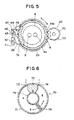
- Fig. 5 is a plan view of still another embodiment of the invention which differs from the embodiment of Fig. 1 in that while the locking mechanism 40 is the same as in the embodiment of Fig. 1, a gear 23a is formed on the outer peripheral portion of the shuttle ring 23 other than the convex portion 26 and a gear 7a is formed on the outer periphery of the rotor 6 in correspondence to the gear 23a.
- Numeral 70 designates a rocking actuator and its exemplary form is shown in Fig. 6.
- Numeral 71 designates a cylindrical body having a partition wall 72 formed therein and hydraulic ports 73 and 74 are formed on the sides of the partition wall 72 of the body 71.
- Numeral 75 designates a rotary member rotatably arranged in the central portion of the body 71 and including a vane 76.
- the outer periphery of the rotary member 75 and the forward end of the vane 76 are respectively in fluid-tight sliding contact with the partition wall 72 and the inner wall of the body 71 thereby forming chambers A and B.
- Numeral 77 designates a gear connected to the rotary member 75 of the rocking actuator 70 and in mesh with the gear 23a of the shuttle ring 23.
- the present invention is applied to a rotary nozzle of the construction shown in Fig. 1, the present invention is also applicable to rotary nozzle of other constructions, e.g., a rotary nozzle of the type in which a frame is fastened to a base member or a shim plate with bolts or the like or a dual hinged-type rotary nozzle in which both a base member and a frame are opened and closed hingedly.
- the hydraulic cylinders are used for the rotor driving mechanism and the locking mechanism, they may be replaced with air cylinders.
- the rocking actuator is not limited to the illustrated one and a rocking actuator of any other mechanism may be used.
- the present invention has the effect of providing a rotor driving mechanism which is not only simple in construction, small in size and light in weight but also low in cost.
Landscapes
- Engineering & Computer Science (AREA)
- Mechanical Engineering (AREA)
- Casting Support Devices, Ladles, And Melt Control Thereby (AREA)
Abstract
Description
- The present invention relates to a rotary nozzle of the type which is attached to the bottom of a molten steel vessel, e.g., a laddle or tundish so that a sliding plate brick is rotated and the opening of a nozzle bore of a fixed plate brick is adjusted thereby controlling the pouring rate of molten steel, and more particularly the invention relates to a turning apparatus for a rotor which holds the sliding plate brick.
- Rotary nozzles have been used widely with laddles for receiving the molten steel tapped from a converter or the like to transport or to pour the molten steel into molds, tundishes for receiving the molten steel from a laddle to pour the molten steel into molds and the like.
- Referring to the accompanying drawings, Fig. 7 is a longitudinal sectional view showing schematically an example of a conventional rotary nozzle, and Fig. 8 is a bottom view of Fig. 7 with a part thereof being omitted. In the Figures, numeral 1 designates a shim plate mounted to the bottom of a laddle, tundish or the like, and 2 a base member attached to the shim plate and formed with a recess for mounting a
fixed plate brick 3 therein and an opening into which atop nozzle 5 is fitted. Numeral 6 designates a rotor rotatably arranged on a movable member 11 through a ball bearing 12, formed with a recess in which asliding plate brick 8 is mounted and an opening into which abottom nozzle 10 is fitted and provided with agear 7 on its upper outer periphery thereof. Numeral 13 designates a frame adapted to accommodate therotor 6 and pivotably attached to the shim plate 1 by ahinge 14. It is to be noted that although not shown, the opposite side to thehinge 14 is secured to the shim member 1 with bolts, levers or the like. Numeral 15 designates springs mounted between the movable member 11 and theframe 13 and they are adapted to press therotor 6 upward and force the sliding surface of thesliding plate brick 8 into close contact with thefixed plate brick 3. - Numeral 16 designates a motor, 17 a reduction gear, and 18 the final-stage gear of the
reduction gear 17 which is in mesh with thegear 7 of therotor 6. - With the construction described above, the operation of the rotary nozzle will now be described. In the illustrated condition, the nozzle bores of the
top nozzle 5, thefixed plate brick 3, thesliding plate brick 8 and thebottom nozzle 10 are located on the same center, and the nozzle bore 9 of thesliding plate brick 8 is in a wide-open position relative to thenozzle bore 4 of thefixed plate brick 3. Therefore, the molten steel in the laddle or the like is poured into a tundish or the like in the maximum amount. To control the rate of pour o fthe molten steel, themotor 16 is operated so that the rotation reduced by thereduction gear 17 is transmitted to therotor 6 through thegears rotor 6 through a desired angle. When this occurs, the opening of thenozzle bores - Where it is desired to perform the desired maintenance, inspection, etc., or to replace the
fixed plate brick 3 and thesliding plate brick 8, it is only necessary to pivotally rotate theframe 13 and therotor 6 received in the former in a door-like manner by thehinge 14 as a pivot, thus exposing the sliding surfaces. - Rotary nozzles of this type have been recently used in large numbers owing to a number of advantages that the maintenance and inspection are easy, that the damages on the surfaces of the
fixed plate brick 3 and thesliding plate brick 8 can be confirmed with the naked eye and they can also be replaced easily and so on. - However, the driving unit for the
rotor 6, that is, themotor 16 and thereduction gear 17 which are attached to the bottom of the laddle or the like are extremely large in size and weight thus making it inconvenient to handle. - As a means of solving this difficulty, it is conceivable to rotate the rotor by a hydraulic cylinder or rocking actuator. However, the range of rotation of the rotor is limited by the stroke of the hydraulic cylinder or the rotational angle of the rocking actuator so that in order to increase the rotation range of the rotor, a hydraulic cylinder with a long and strong actuator or a rocking actuator with a large linkage is required and the above-mentioned problem still remains unsolved.
- The present invention has been made to overcome the foregoing deficiencies and it is an object of the invention to provide a rotary nozzle equipped with a rotor driving unit which is small in size and light in weight.
- To accomplish the above object, in accordance with the present invention there is thus provided a rotary nozzle including a rotor formed with a plurality of notched engaging portions at equal intervals on its outer periphery, a turning member rotatably arranged along the rotor and including detent means adapted to engage with the engaging portions and a locking mechanism for bringing the detent means into and out of engagement with the engaging portions, and a hydraulic cylinder having an actuator connected to the turning member.
- In accordance with a further feature of the present invention, a gear is formed on the outer periphery of the turning member, and the hydraulic cylinder is replaced with a rocking actuator whose output side is connected to a gear which in turn is connected to the gear of the turning member.
- In accordance with still further feature of the present invention, a belt member having a lining on its inner surface is arranged on the outer periphery of the rotor in a manner that the ends of the belt member are attached to a connecting member having a function of tightening and loosing the belt member, and the connecting member is connected to the actuator of the hydraulic cylinder.
- In accordance with the invention, there is an effect that by operating the hydraulic cylinder or the rocking actuator, the rotor coupled with the turning member as a unit is selectively caused to make stepping rotary movements in the forward and backward directions through the turning member connected to the hydraulic cylinder or the rocking actuator and also the rotor is controlled by the locking mechanism, thereby rotating the rotor through a wide range of angles.
- There is another effect that by tightening the belt member and operating the hydraulic cylinder connected thereto, the rotor is rotated in correspondence to the stroke of the actuator of the hydraulic cylinder and also the tightening and loosening of the belt member are repeated, thereby rotating the rotor through a wide range of angles.
-
- Fig. 1 is a longitudinal sectional view showing an embodiment of the present invention.
- Fig. 2 is a partly cutaway sectional view taken along the line A-A of Fig. 1.
- Fig. 2A shows a modification of the embodiment of Fig. 2.
- Figs. 3, 4 and 5 are plan views (corresponding to the section along the line A-A of Fig. 1) showing respectively another embodiments of the invention.
- Fig. 6 is a partial sectional view of Fig. 5.
- Fig. 7 is a front view showing an example of a conventional rotary nozzle with a part thereof shown in section.
- Fig. 8 is a bottom view of Fig. 7.
- Fig. 1 is a longitudinal sectional view of an embodiment of the present invention, and Fig. 2 is a sectional view taken along the line A-A of Fig. 1. It is to be noted that those component parts which are identical or equivalent to their counterparts in the conventional rotary nozzle of Figs. 7 and 8 are designated by the same reference numerals and their explanation will be omitted. Numeral 21 designates a ring portion provided on the upper outer periphery of a
rotor 6 to be integral therewith and a plurality of notchedengaging portions 22a to 22n are formed on its outer periphery at equal intervals (at intervals of 30o in this embodiment). Numeral 23 designates a shuttle ring having a C sectional shape and formed on its inner periphery with agroove 24 rotatably loose-fitted on thering portion 21 of therotor 6. Theshuttle ring 23 includes anarm 25 and an outwardly projectingconvex portion 26 on the opposite side to thearm 25. Numeral 42 designates a hydraulic cylinder attached by asupport arm 41 to one side of theconvex portion 26 of the shuttle ring 23 (in this embodiment theconvex portion 26 is arranged over an extent of about 60o corresponding to the intervals of two of theengaging portions 22a to 22n). Numeral 44 designates a substantially Z-shaped lock member formed at its one end with adetent portion 45 for selectively engaging with theengaging portions 22a to 22n formed on thering portion 21 and it is inserted into a slot 26a formed in theconvex portion 26 with its substantially central portion being rotatably pivoted by apin 46. The other end of thelock member 44 is pivotably connected to anactuator 43 of thehydraulic cylinder 42. It is to be noted that these component parts form alocking mechanism 40 for therotor 6. - Numeral 28 designates a hydraulic cylinder mounted on a shim plate 1 by a
fixture 31 and itsactuator 29 has its forward end pivotably connected to thearm 25 of theshuttle ring 23 by apin 30. It is to be noted that these component parts form adriving mechanism 20 for therotor 6. - With the construction described above, the operation of the present embodiment will now be described.
- (1) In the condition of Figs. 1 and 2, the center of the nozzle bore 9 of the
sliding plate brick 8 is positioned on the line 0-0 connecting the centers of thepin 30 and therotor 6 so that the nozzle bores 4 and 9 of thefixed plate brick 3 and thesliding plate brick 8 are aligned and are in a fully opened condition. - (2) Assuming that the
actuator 29 of thehydraulic cylinder 28 is retreated for example in the direction of an arrow b, theshuttle ring 23 is rotated in the direction of an arrow b so that thedetent portion 45 of thelock member 44 is engaged with theengaging portion 22a and therefore therotor 6 which is united with theshuttle ring 23 is rotated in the direction of the arrow b. - (3) When the operation of the
hydraulic cylinder 28 is stopped after theshuttle ring 23 has been rotated 30o, for example, the nozzle bore 9 of thesliding plate brick 8 is moved to the corresponding position (shown by the broken line in Fig. 2) and a part of thenozzle bore 4 of thefixed plate brick 3 is closed. - (4) Then, as the
actuator 43 of thehydraulic cylinder 42 of thelocking mechanism 4 is moved forward or in the direction of an arrow a, thelock member 44 is pivoted about thepin 46 in the clockwise direction in the Figure and thedetent portion 45 is disengaged with theengaging portion 22a. - (5) In this condition, when the
actuator 29 of thehydraulic cylinder 28 of thedriving mechanism 20 is moved forward in the direction of an arrow a, due to the fact that theshuttle ring 23 and therotor 6 has been uncoupled, only theshuttle ring 23 is rotated in the direction of the arrow a. If, for example, thehydraulic cylinder 28 is stopped after theshuttle ring 23 has been rotated through 30o, thedetent portion 45 of thelock member 44 is stopped in opposition to the nextengaging portion 22n of therotor 6. - (6) In this condition, if the
actuator 43 of thehydrauric cylinder 42 is moved backward, thelock member 44 is pivoted about thepin 46 in the counterclockwise direction and thedetent portion 45 is engaged with theengaging portion 22n thus providing locking again. - (7) By thus rotating the
rotor 6 in the direction of the arrow a or b to adjust thenozzle bores sliding plate brick 8 is damaged by frequent charges, by rotating therotor 6 through 180o in the direction of the arrow a or b in the above-mentioned manner, anunused nozzle bore 9 can be positioned opposite to the nozzle bore 4 of thefixed plate brick 3. - Referring now to Fig. 2A, there is illustrated a modification of the embodiment of Fig. 2. This modification features that differing from the engaging means and locking means of Fig. 2, its locking means brings into and out of engagement with the notched
engaging portions 22a to 22n a detent portion formed at one end of apiston rod 84 of apiston 83 operated by ahydraulic cylinder 82 which is directly attached to the turning member. - Referring now to Fig. 3, there is illustrated another embodiment of the invention (corresponding to the sectional view taken along the line A-A of Fig. 1).
- This embodiment differs from the embodiment of Fig. 1 in that a
gear 7 is formed on thering portion 21 of therotor 6, and also a substantially triangular rocker 50 formed on its sides withlocking pawls 51 and 51a for engagement with thegear 7 of therotor 6 is pivotably attached by apivot pint 52 to theconvex portion 26. It is to be noted that the rocker 50 is pressed from its sides bysprings 53 and 53a, respectively, and the spring forces of thesprings 53 and 53a are adjustable by a control mechanism (not shown). Note that adriving mechanism 20 is the same as the embodiment of Fig. 1. - With the present embodiment constructed as described above, if, for example, the locking
pawl 51 is engaged with thegear 7 of therotor 6 thereby decreasing the spring force of the spring 53, a pivoting force in the direction of the arrow is imparted to the rocker 50 by thespring 53a, thereby pressing the side of the lockingpawl 51 against thegear 7. Thus, while the rotation of theshuttle ring 23 in the direction of the arrow a causes therotor 6 to rotate in the direction of the arrow a, the rotation of theshuttle ring 23 in the direction of the arrow b rotates only theshuttle ring 23 and therotor 6 is not rotated. In the like manner, when the locking pawl 51a is engaged with thegear 7 so that the sring force of thespring 53a is decreased, the rotation of theshuttle ring 23 in the direction of the arrow b causes the rotation of therotor 6, whereas the rotation of theshuttle ring 23 in the direction of the arrow a results in no rotation of therotor 6. - As a result, by repeating the operation of moving forward the
actuator 29 of thehydraulic cylinder 28 to the extent of the stroke, for example, thereby rotating therotor 6 in one direction, then moving backward theactuator 29 to rotate only theshuttle ring 23 and then bringing the same locking pawl into engagement with thegear 7 and again moving theactuator 29 forward, therotor 6 can be rotated a wide range of angles in the direction of the arrow a or b thereby adjusting the degree of opening of the nozzle bores 4 and 9. - Referring now to Fig. 4, there is illustrated a plan view of another embodiment of the invention which differs from the embodiment of Fig. 1 as follows.
Numeral 61 designates a belt member such as a steel belt wound on the outer periphery of therotor 6 and its inner surface is provided with a lining 62 composed of a heat resisting material.Numeral 63 designates a substantially inverted Y-shaped connecting member whose body portion has its forward end pivotably connected to theactuator 29 of thehydraulic cylinder 28 by thepin 30 and itsarms belt member 61.Numeral 65 designates a hydraulic cylinder disposed in the body portion of the connectingmember 63 and arod 67 of itspiston 66 is brought out from between thearms member 63 and has afriction member 68 composed of a heat resisting material attached to the forward end thereof. - The operation of this embodiment will now be described.
- (1) In order to rotate the
rotor 6, hydraulic pressure is applied to the chamber A of thehydraulic cylinder 65 for the connectingmember 63 so that thepiston 66 is moved forward in the direction of an arrow a to press thefriction member 68 against the outer periphery of therotor 6 and the connectingmember 63 is displaced in the direction of an arrow b thereby binding therotor 6 by thebelt member 61. - (2) In this condition, by moving the
actuator 29 of thehydraulic cylinder 28 forward or backward within the extent of its stroke, therotor 6 can be rotated correspondingly. - (3) In order to rotate the
rotor 6 further, hydraulic pressure is applied to the chamber B of thehydraulic cylinder 65 to move thepiston 66 back in the direction of an arrow b, thus loosening the pressing on thefriction member 67 and the binding of thebelt member 61 and thereby setting therotor 6 free. - In this condition, after the
actuator 29 of thehydraulic cylinder 28 has been moved forward or backward, thefriction member 68 is pressed against therotor 6 and thebelt member 61 is tightened thereby rotating therotor 6 further. By performing such operation repeatedly, therotor 6 is rotated to adjust the nozzle bores 4 and 9 to a desired opening. - Fig. 5 is a plan view of still another embodiment of the invention which differs from the embodiment of Fig. 1 in that while the
locking mechanism 40 is the same as in the embodiment of Fig. 1, a gear 23a is formed on the outer peripheral portion of theshuttle ring 23 other than theconvex portion 26 and agear 7a is formed on the outer periphery of therotor 6 in correspondence to the gear 23a.Numeral 70 designates a rocking actuator and its exemplary form is shown in Fig. 6.Numeral 71 designates a cylindrical body having apartition wall 72 formed therein andhydraulic ports partition wall 72 of thebody 71.Numeral 75 designates a rotary member rotatably arranged in the central portion of thebody 71 and including avane 76. The outer periphery of therotary member 75 and the forward end of thevane 76 are respectively in fluid-tight sliding contact with thepartition wall 72 and the inner wall of thebody 71 thereby forming chambers A andB. Numeral 77 designates a gear connected to therotary member 75 of the rockingactuator 70 and in mesh with the gear 23a of theshuttle ring 23. - Assuming now that the
hydraulic port 74 of the rockingactuator 70 is opened and hydraulic pressure is introduced into the chamber A through thehydraulic port 73, for example, the hydraulic pressure is applied to thevane 76 and therotary member 75 is rotated in the direction of an arrow a. As a result, thegear 77 connected to therotary member 75 is driven in the direction of an arrow a and theshuttle ring 23 connected to thegear 77 and therotor 6 are rotated in the direction of the arrow a. In the like manner, when thehydraulic port 73 is opened and hydraulic pressure is introduced into the chamber B through thehydraulic port 74, therotary member 75 is rotated in the direction of an arrow b and theshuttle ring 23 and therotor 6 are rotated in the direction of an arrow b through thegear 77 coupled to therotary member 75. - In this way, by rotating the
rotor 6 in the direction of the arrow a or b bY the rockingactuator 70 and operating thelocking mechanism 40, the degree of opening of the nozzle bores 4 and 9 is adjusted to a desired value or alternatively the slidingplate brick 8 is rotated through 180o thereby positioning the unused nozzle bore 9a opposite to thenozzle bore 4. - While, in the foregoing description, the present invention is applied to a rotary nozzle of the construction shown in Fig. 1, the present invention is also applicable to rotary nozzle of other constructions, e.g., a rotary nozzle of the type in which a frame is fastened to a base member or a shim plate with bolts or the like or a dual hinged-type rotary nozzle in which both a base member and a frame are opened and closed hingedly.
- In addition, while the hydraulic cylinders are used for the rotor driving mechanism and the locking mechanism, they may be replaced with air cylinders. Also, the rocking actuator is not limited to the illustrated one and a rocking actuator of any other mechanism may be used.
- As described hereinabove in detail, by virtue of the fact that a hydraulic cylinder of a relatively small stroke or a rocking actuator of a small rotational angle is used and it is aided by the operation of a control mechanism to rotate a rotor through a wide range, the present invention has the effect of providing a rotor driving mechanism which is not only simple in construction, small in size and light in weight but also low in cost.
Claims (10)
engaging means formed on an outer periphery of said rotor; and
turning means arranged to rotate said rotor, said turning means including detent means adapted for engagement with said engaging means, and locking means adapted to bring said detent means into and out of engagement with said engaging means, said turning means being connected to an actuator of a hydraulic cylinder attached to said molten steel vessel.
Applications Claiming Priority (2)
| Application Number | Priority Date | Filing Date | Title |
|---|---|---|---|
| JP200081/88 | 1988-08-12 | ||
| JP63200081A JPH0252165A (en) | 1988-08-12 | 1988-08-12 | Rotary nozzle |
Publications (2)
| Publication Number | Publication Date |
|---|---|
| EP0357227A1 true EP0357227A1 (en) | 1990-03-07 |
| EP0357227B1 EP0357227B1 (en) | 1992-09-30 |
Family
ID=16418536
Family Applications (1)
| Application Number | Title | Priority Date | Filing Date |
|---|---|---|---|
| EP89307736A Expired - Lifetime EP0357227B1 (en) | 1988-08-12 | 1989-07-28 | Rotary nozzle |
Country Status (9)
| Country | Link |
|---|---|
| US (1) | US4998650A (en) |
| EP (1) | EP0357227B1 (en) |
| JP (1) | JPH0252165A (en) |
| KR (1) | KR900002867A (en) |
| BR (1) | BR8904056A (en) |
| CA (1) | CA1311612C (en) |
| DE (1) | DE68903080T2 (en) |
| ES (1) | ES2035570T3 (en) |
| ZA (1) | ZA895611B (en) |
Cited By (7)
| Publication number | Priority date | Publication date | Assignee | Title |
|---|---|---|---|---|
| GB2275009A (en) * | 1993-02-16 | 1994-08-17 | Bruehl Aluminiumtechnik | Hot metal container discharge outlet lock |
| BE1006674A5 (en) * | 1992-01-29 | 1994-11-16 | Nippon Rotary Nozzle Co Ltd | Rotary nozzle. |
| GB2275010B (en) * | 1993-02-16 | 1996-09-25 | Bruehl Aluminiumtechnik | Process of filling a mould |
| CN1046644C (en) * | 1990-07-04 | 1999-11-24 | 国际工业工程有限公司 | Improved device for introducing and exchanging casting tube |
| WO2000071953A1 (en) * | 1999-05-19 | 2000-11-30 | Sms Demag Ag | Method and device for holding and tapping molten metals |
| EP1698412A1 (en) * | 2003-12-24 | 2006-09-06 | JFE Engineering Corporation | Poured molten metal quantity control device |
| RU2484923C1 (en) * | 2012-03-11 | 2013-06-20 | Научно-производственное республиканское унитарное предприятие "НПО "Центр" | Casting ladle |
Families Citing this family (4)
| Publication number | Priority date | Publication date | Assignee | Title |
|---|---|---|---|---|
| JP2005262238A (en) * | 2004-03-16 | 2005-09-29 | Jfe Engineering Kk | Sliding nozzle device and molten metal pouring apparatus |
| EP1707291A1 (en) * | 2005-03-10 | 2006-10-04 | Tech-Gate S.A. | A linear sliding gate valve for a metallurgical vessel |
| JP5958566B2 (en) * | 2015-01-16 | 2016-08-02 | 品川リフラクトリーズ株式会社 | Slab continuous casting equipment |
| EP3424618B1 (en) * | 2017-07-05 | 2021-03-10 | Refractory Intellectual Property GmbH & Co. KG | Sliding closure for a vessel containing molten metal |
Citations (5)
| Publication number | Priority date | Publication date | Assignee | Title |
|---|---|---|---|---|
| US3430644A (en) * | 1967-02-24 | 1969-03-04 | United States Steel Corp | Rotary gate for bottom pour vessel |
| US3780916A (en) * | 1971-12-17 | 1973-12-25 | United States Steel Corp | Rotary gate for bottom pour vessel having removable nozzles |
| FR2457141A1 (en) * | 1979-05-25 | 1980-12-19 | Stopinc Ag | CLOSING DEVICE WITH ROTARY SHUTTER FOR METALLURGICAL CONTAINERS |
| FR2522554A1 (en) * | 1982-03-05 | 1983-09-09 | Nippon Kokan Kk | DOUBLE DOOR TYPE ROTARY NOZZLE FOR CAST IRON OR STEEL CASTING POCKET |
| EP0128841A1 (en) * | 1983-06-13 | 1984-12-19 | Nippon Kokan Kabushiki Kaisha | Door-type rotary nozzle |
Family Cites Families (1)
| Publication number | Priority date | Publication date | Assignee | Title |
|---|---|---|---|---|
| GB2133505B (en) * | 1982-12-14 | 1987-04-15 | Nippon Kokan Kk | Rotary nozzle system for metallurgical vessels |
-
1988
- 1988-08-12 JP JP63200081A patent/JPH0252165A/en active Pending
-
1989
- 1989-07-17 US US07/381,120 patent/US4998650A/en not_active Expired - Fee Related
- 1989-07-20 CA CA000606176A patent/CA1311612C/en not_active Expired - Lifetime
- 1989-07-24 ZA ZA895611A patent/ZA895611B/en unknown
- 1989-07-28 ES ES198989307736T patent/ES2035570T3/en not_active Expired - Lifetime
- 1989-07-28 EP EP89307736A patent/EP0357227B1/en not_active Expired - Lifetime
- 1989-07-28 DE DE8989307736T patent/DE68903080T2/en not_active Expired - Fee Related
- 1989-08-11 BR BR898904056A patent/BR8904056A/en not_active IP Right Cessation
- 1989-08-12 KR KR1019890011526A patent/KR900002867A/en not_active Application Discontinuation
Patent Citations (5)
| Publication number | Priority date | Publication date | Assignee | Title |
|---|---|---|---|---|
| US3430644A (en) * | 1967-02-24 | 1969-03-04 | United States Steel Corp | Rotary gate for bottom pour vessel |
| US3780916A (en) * | 1971-12-17 | 1973-12-25 | United States Steel Corp | Rotary gate for bottom pour vessel having removable nozzles |
| FR2457141A1 (en) * | 1979-05-25 | 1980-12-19 | Stopinc Ag | CLOSING DEVICE WITH ROTARY SHUTTER FOR METALLURGICAL CONTAINERS |
| FR2522554A1 (en) * | 1982-03-05 | 1983-09-09 | Nippon Kokan Kk | DOUBLE DOOR TYPE ROTARY NOZZLE FOR CAST IRON OR STEEL CASTING POCKET |
| EP0128841A1 (en) * | 1983-06-13 | 1984-12-19 | Nippon Kokan Kabushiki Kaisha | Door-type rotary nozzle |
Cited By (11)
| Publication number | Priority date | Publication date | Assignee | Title |
|---|---|---|---|---|
| CN1046644C (en) * | 1990-07-04 | 1999-11-24 | 国际工业工程有限公司 | Improved device for introducing and exchanging casting tube |
| BE1006674A5 (en) * | 1992-01-29 | 1994-11-16 | Nippon Rotary Nozzle Co Ltd | Rotary nozzle. |
| GB2275009A (en) * | 1993-02-16 | 1994-08-17 | Bruehl Aluminiumtechnik | Hot metal container discharge outlet lock |
| GB2275010B (en) * | 1993-02-16 | 1996-09-25 | Bruehl Aluminiumtechnik | Process of filling a mould |
| GB2275009B (en) * | 1993-02-16 | 1996-09-25 | Bruehl Aluminiumtechnik | Hot metal container discharge outlet lock |
| ES2112686A1 (en) * | 1993-02-16 | 1998-04-01 | Bruehl Aluminiumtechnik | Rotary slide valve for metallurgical vessels |
| WO2000071953A1 (en) * | 1999-05-19 | 2000-11-30 | Sms Demag Ag | Method and device for holding and tapping molten metals |
| EP1698412A1 (en) * | 2003-12-24 | 2006-09-06 | JFE Engineering Corporation | Poured molten metal quantity control device |
| EP1698412A4 (en) * | 2003-12-24 | 2007-04-04 | Jfe Eng Corp | Poured molten metal quantity control device |
| US7546937B2 (en) | 2003-12-24 | 2009-06-16 | Jfe Engineering Corporation | Poured molten metal quantity control device |
| RU2484923C1 (en) * | 2012-03-11 | 2013-06-20 | Научно-производственное республиканское унитарное предприятие "НПО "Центр" | Casting ladle |
Also Published As
| Publication number | Publication date |
|---|---|
| CA1311612C (en) | 1992-12-22 |
| ES2035570T3 (en) | 1993-04-16 |
| ZA895611B (en) | 1990-04-25 |
| US4998650A (en) | 1991-03-12 |
| DE68903080D1 (en) | 1992-11-05 |
| KR900002867A (en) | 1990-03-23 |
| EP0357227B1 (en) | 1992-09-30 |
| BR8904056A (en) | 1990-03-20 |
| DE68903080T2 (en) | 1993-04-08 |
| JPH0252165A (en) | 1990-02-21 |
Similar Documents
| Publication | Publication Date | Title |
|---|---|---|
| EP0357227B1 (en) | Rotary nozzle | |
| CA1039258A (en) | Swing valve | |
| US4905973A (en) | Power operated clamp with externally mounted adjustable clamp arm | |
| DE4431353C1 (en) | Brake caliper unit for disc brakes of vehicles, in particular rail vehicles | |
| CA1036789A (en) | Slidable gate mechanism | |
| GB2093944A (en) | Continuous ratchet drive | |
| CA1232892A (en) | Mechanism for actuating a proportioning valve | |
| US5076166A (en) | Arrangement for the accurately positioned quick-action clamping and tensioning of printing plates | |
| JPH0335481Y2 (en) | ||
| US5213035A (en) | Device for changing-over a gripper control on a gripper cylinder of a turning device in a sheet-fed rotary printing machine for first-form and perfector printing | |
| CA2242501C (en) | Sliding gate valve for a vessel containing molten metal | |
| JPS5941263A (en) | Device for vibrating and moving doctor which can be reciprocated in longitudinal direction | |
| US4235567A (en) | Material handling machine with adjustable speed-power relationship for boom movement | |
| US5158019A (en) | Device for infinitely variable adjustment of the axial spreading movement of distributing rollers | |
| EP1001201B1 (en) | Linkage locking device | |
| US5473970A (en) | Interlocking change-over valve system | |
| JP4040472B2 (en) | Fixing mechanism of cargo cover hatch cover opening and closing device | |
| SU1574872A1 (en) | Valve gear of internal combustion engine with controllable phases | |
| EP0130205A1 (en) | Motion mechanism for obtaining several movements from a single power unit | |
| GB2149888A (en) | Sliding gate valves | |
| US4457459A (en) | Valve suitable for controlling teeming from furnace tapholes | |
| SU1230896A1 (en) | Device for closing covers of railway open wagon hatches | |
| US3358859A (en) | Material handling apparatus | |
| CS198234B2 (en) | Evacuating valve for receptacles for the raw gas particularly for the shaft furnaces | |
| GB2181777A (en) | Fastening device |
Legal Events
| Date | Code | Title | Description |
|---|---|---|---|
| PUAI | Public reference made under article 153(3) epc to a published international application that has entered the european phase |
Free format text: ORIGINAL CODE: 0009012 |
|
| AK | Designated contracting states |
Kind code of ref document: A1 Designated state(s): BE DE ES FR GB GR IT |
|
| 17P | Request for examination filed |
Effective date: 19900820 |
|
| 17Q | First examination report despatched |
Effective date: 19911212 |
|
| GRAA | (expected) grant |
Free format text: ORIGINAL CODE: 0009210 |
|
| AK | Designated contracting states |
Kind code of ref document: B1 Designated state(s): BE DE ES FR GB GR IT |
|
| PG25 | Lapsed in a contracting state [announced via postgrant information from national office to epo] |
Ref country code: GR Free format text: LAPSE BECAUSE OF FAILURE TO SUBMIT A TRANSLATION OF THE DESCRIPTION OR TO PAY THE FEE WITHIN THE PRESCRIBED TIME-LIMIT Effective date: 19920930 |
|
| REF | Corresponds to: |
Ref document number: 68903080 Country of ref document: DE Date of ref document: 19921105 |
|
| ITF | It: translation for a ep patent filed | ||
| ET | Fr: translation filed | ||
| REG | Reference to a national code |
Ref country code: ES Ref legal event code: FG2A Ref document number: 2035570 Country of ref document: ES Kind code of ref document: T3 |
|
| PG25 | Lapsed in a contracting state [announced via postgrant information from national office to epo] |
Ref country code: ES Free format text: LAPSE BECAUSE OF THE APPLICANT RENOUNCES Effective date: 19930729 |
|
| PLBE | No opposition filed within time limit |
Free format text: ORIGINAL CODE: 0009261 |
|
| STAA | Information on the status of an ep patent application or granted ep patent |
Free format text: STATUS: NO OPPOSITION FILED WITHIN TIME LIMIT |
|
| 26N | No opposition filed | ||
| PGFP | Annual fee paid to national office [announced via postgrant information from national office to epo] |
Ref country code: FR Payment date: 19950711 Year of fee payment: 7 |
|
| PGFP | Annual fee paid to national office [announced via postgrant information from national office to epo] |
Ref country code: GB Payment date: 19950717 Year of fee payment: 7 |
|
| PGFP | Annual fee paid to national office [announced via postgrant information from national office to epo] |
Ref country code: DE Payment date: 19950725 Year of fee payment: 7 |
|
| PGFP | Annual fee paid to national office [announced via postgrant information from national office to epo] |
Ref country code: BE Payment date: 19950911 Year of fee payment: 7 |
|
| PG25 | Lapsed in a contracting state [announced via postgrant information from national office to epo] |
Ref country code: GB Effective date: 19960728 |
|
| PG25 | Lapsed in a contracting state [announced via postgrant information from national office to epo] |
Ref country code: BE Effective date: 19960731 |
|
| BERE | Be: lapsed |
Owner name: TOKYO YOGYO K.K. Effective date: 19960731 Owner name: KOKAN KIKAI KOGYO K.K. Effective date: 19960731 Owner name: NKK CORP. Effective date: 19960731 Owner name: NIPPON ROTARY NOZZLE CO. LTD Effective date: 19960731 |
|
| GBPC | Gb: european patent ceased through non-payment of renewal fee |
Effective date: 19960728 |
|
| PG25 | Lapsed in a contracting state [announced via postgrant information from national office to epo] |
Ref country code: FR Effective date: 19970328 |
|
| PG25 | Lapsed in a contracting state [announced via postgrant information from national office to epo] |
Ref country code: DE Effective date: 19970402 |
|
| REG | Reference to a national code |
Ref country code: FR Ref legal event code: ST |
|
| REG | Reference to a national code |
Ref country code: ES Ref legal event code: FD2A Effective date: 20001102 |
|
| PG25 | Lapsed in a contracting state [announced via postgrant information from national office to epo] |
Ref country code: IT Free format text: LAPSE BECAUSE OF NON-PAYMENT OF DUE FEES;WARNING: LAPSES OF ITALIAN PATENTS WITH EFFECTIVE DATE BEFORE 2007 MAY HAVE OCCURRED AT ANY TIME BEFORE 2007. THE CORRECT EFFECTIVE DATE MAY BE DIFFERENT FROM THE ONE RECORDED. Effective date: 20050728 |