EP0357183A1 - Automotive electrical apparatus having a starter/generator induction machine - Google Patents
Automotive electrical apparatus having a starter/generator induction machine Download PDFInfo
- Publication number
- EP0357183A1 EP0357183A1 EP89306027A EP89306027A EP0357183A1 EP 0357183 A1 EP0357183 A1 EP 0357183A1 EP 89306027 A EP89306027 A EP 89306027A EP 89306027 A EP89306027 A EP 89306027A EP 0357183 A1 EP0357183 A1 EP 0357183A1
- Authority
- EP
- European Patent Office
- Prior art keywords
- induction machine
- voltage
- storage battery
- machine
- power frequency
- Prior art date
- Legal status (The legal status is an assumption and is not a legal conclusion. Google has not performed a legal analysis and makes no representation as to the accuracy of the status listed.)
- Granted
Links
- 230000006698 induction Effects 0.000 title claims abstract description 40
- 239000007858 starting material Substances 0.000 title 1
- 238000000034 method Methods 0.000 claims abstract description 4
- 238000002485 combustion reaction Methods 0.000 claims description 4
- 230000008878 coupling Effects 0.000 claims description 2
- 238000010168 coupling process Methods 0.000 claims description 2
- 238000005859 coupling reaction Methods 0.000 claims description 2
- 230000005611 electricity Effects 0.000 claims description 2
- 230000002902 bimodal effect Effects 0.000 abstract description 15
- 230000007704 transition Effects 0.000 abstract description 14
- 230000009467 reduction Effects 0.000 abstract description 3
- 238000010586 diagram Methods 0.000 description 20
- 230000005284 excitation Effects 0.000 description 19
- 238000004804 winding Methods 0.000 description 11
- 239000003990 capacitor Substances 0.000 description 5
- NCGICGYLBXGBGN-UHFFFAOYSA-N 3-morpholin-4-yl-1-oxa-3-azonia-2-azanidacyclopent-3-en-5-imine;hydrochloride Chemical compound Cl.[N-]1OC(=N)C=[N+]1N1CCOCC1 NCGICGYLBXGBGN-UHFFFAOYSA-N 0.000 description 4
- 101100421779 Arabidopsis thaliana SNL3 gene Proteins 0.000 description 4
- 101100042631 Saccharomyces cerevisiae (strain ATCC 204508 / S288c) SIN3 gene Proteins 0.000 description 4
- 238000004590 computer program Methods 0.000 description 3
- 230000000977 initiatory effect Effects 0.000 description 2
- 230000004044 response Effects 0.000 description 2
- 102100023882 Endoribonuclease ZC3H12A Human genes 0.000 description 1
- 101710112715 Endoribonuclease ZC3H12A Proteins 0.000 description 1
- 230000000295 complement effect Effects 0.000 description 1
- 230000001010 compromised effect Effects 0.000 description 1
- 230000001276 controlling effect Effects 0.000 description 1
- 230000014509 gene expression Effects 0.000 description 1
- 238000002955 isolation Methods 0.000 description 1
- 238000003475 lamination Methods 0.000 description 1
- 230000003287 optical effect Effects 0.000 description 1
- QGVYYLZOAMMKAH-UHFFFAOYSA-N pegnivacogin Chemical compound COCCOC(=O)NCCCCC(NC(=O)OCCOC)C(=O)NCCCCCCOP(=O)(O)O QGVYYLZOAMMKAH-UHFFFAOYSA-N 0.000 description 1
- 230000008569 process Effects 0.000 description 1
- 230000001105 regulatory effect Effects 0.000 description 1
- 230000000630 rising effect Effects 0.000 description 1
- 230000011664 signaling Effects 0.000 description 1
- 230000001052 transient effect Effects 0.000 description 1
- 230000001960 triggered effect Effects 0.000 description 1
Images


Classifications
-
- B—PERFORMING OPERATIONS; TRANSPORTING
- B60—VEHICLES IN GENERAL
- B60K—ARRANGEMENT OR MOUNTING OF PROPULSION UNITS OR OF TRANSMISSIONS IN VEHICLES; ARRANGEMENT OR MOUNTING OF PLURAL DIVERSE PRIME-MOVERS IN VEHICLES; AUXILIARY DRIVES FOR VEHICLES; INSTRUMENTATION OR DASHBOARDS FOR VEHICLES; ARRANGEMENTS IN CONNECTION WITH COOLING, AIR INTAKE, GAS EXHAUST OR FUEL SUPPLY OF PROPULSION UNITS IN VEHICLES
- B60K1/00—Arrangement or mounting of electrical propulsion units
- B60K1/04—Arrangement or mounting of electrical propulsion units of the electric storage means for propulsion
-
- H—ELECTRICITY
- H02—GENERATION; CONVERSION OR DISTRIBUTION OF ELECTRIC POWER
- H02P—CONTROL OR REGULATION OF ELECTRIC MOTORS, ELECTRIC GENERATORS OR DYNAMO-ELECTRIC CONVERTERS; CONTROLLING TRANSFORMERS, REACTORS OR CHOKE COILS
- H02P9/00—Arrangements for controlling electric generators for the purpose of obtaining a desired output
- H02P9/14—Arrangements for controlling electric generators for the purpose of obtaining a desired output by variation of field
- H02P9/26—Arrangements for controlling electric generators for the purpose of obtaining a desired output by variation of field using discharge tubes or semiconductor devices
- H02P9/30—Arrangements for controlling electric generators for the purpose of obtaining a desired output by variation of field using discharge tubes or semiconductor devices using semiconductor devices
- H02P9/305—Arrangements for controlling electric generators for the purpose of obtaining a desired output by variation of field using discharge tubes or semiconductor devices using semiconductor devices controlling voltage
- H02P9/307—Arrangements for controlling electric generators for the purpose of obtaining a desired output by variation of field using discharge tubes or semiconductor devices using semiconductor devices controlling voltage more than one voltage output
-
- F—MECHANICAL ENGINEERING; LIGHTING; HEATING; WEAPONS; BLASTING
- F02—COMBUSTION ENGINES; HOT-GAS OR COMBUSTION-PRODUCT ENGINE PLANTS
- F02N—STARTING OF COMBUSTION ENGINES; STARTING AIDS FOR SUCH ENGINES, NOT OTHERWISE PROVIDED FOR
- F02N11/00—Starting of engines by means of electric motors
- F02N11/04—Starting of engines by means of electric motors the motors being associated with current generators
-
- H—ELECTRICITY
- H02—GENERATION; CONVERSION OR DISTRIBUTION OF ELECTRIC POWER
- H02J—CIRCUIT ARRANGEMENTS OR SYSTEMS FOR SUPPLYING OR DISTRIBUTING ELECTRIC POWER; SYSTEMS FOR STORING ELECTRIC ENERGY
- H02J7/00—Circuit arrangements for charging or depolarising batteries or for supplying loads from batteries
- H02J7/14—Circuit arrangements for charging or depolarising batteries or for supplying loads from batteries for charging batteries from dynamo-electric generators driven at varying speed, e.g. on vehicle
- H02J7/1469—Regulation of the charging current or voltage otherwise than by variation of field
- H02J7/1492—Regulation of the charging current or voltage otherwise than by variation of field by means of controlling devices between the generator output and the battery
-
- H—ELECTRICITY
- H02—GENERATION; CONVERSION OR DISTRIBUTION OF ELECTRIC POWER
- H02P—CONTROL OR REGULATION OF ELECTRIC MOTORS, ELECTRIC GENERATORS OR DYNAMO-ELECTRIC CONVERTERS; CONTROLLING TRANSFORMERS, REACTORS OR CHOKE COILS
- H02P9/00—Arrangements for controlling electric generators for the purpose of obtaining a desired output
- H02P9/04—Control effected upon non-electric prime mover and dependent upon electric output value of the generator
-
- H—ELECTRICITY
- H02—GENERATION; CONVERSION OR DISTRIBUTION OF ELECTRIC POWER
- H02P—CONTROL OR REGULATION OF ELECTRIC MOTORS, ELECTRIC GENERATORS OR DYNAMO-ELECTRIC CONVERTERS; CONTROLLING TRANSFORMERS, REACTORS OR CHOKE COILS
- H02P9/00—Arrangements for controlling electric generators for the purpose of obtaining a desired output
- H02P9/08—Control of generator circuit during starting or stopping of driving means, e.g. for initiating excitation
-
- Y—GENERAL TAGGING OF NEW TECHNOLOGICAL DEVELOPMENTS; GENERAL TAGGING OF CROSS-SECTIONAL TECHNOLOGIES SPANNING OVER SEVERAL SECTIONS OF THE IPC; TECHNICAL SUBJECTS COVERED BY FORMER USPC CROSS-REFERENCE ART COLLECTIONS [XRACs] AND DIGESTS
- Y02—TECHNOLOGIES OR APPLICATIONS FOR MITIGATION OR ADAPTATION AGAINST CLIMATE CHANGE
- Y02T—CLIMATE CHANGE MITIGATION TECHNOLOGIES RELATED TO TRANSPORTATION
- Y02T10/00—Road transport of goods or passengers
- Y02T10/60—Other road transportation technologies with climate change mitigation effect
- Y02T10/70—Energy storage systems for electromobility, e.g. batteries
Definitions
- This invention pertains to an automotive electrical apparatus employing a single electrical machine for both starting and generating functions, and more particularly to such apparatus in which the single electrical machine is an induction machine.
- Conventional electrical apparatus for automobiles employing internal combustion engines generally include one electrical machine (cranking motor) operated as a motor for cranking the engine during starting, and a separate electrical machine (generator/alternator) for generating electricity during operation of the engine.
- one electrical machine cranking motor
- a separate electrical machine generator/alternator
- An automotive electrical apparatus in accordance with the present invention is characterised by the features specified in the characterising portion of claim 1.
- the present invention is directed to a high efficiency automotive electrical apparatus and method of control employing an asynchronous induction machine for performing both starting and generating functions.
- the induction machine is coupled to the engine through a bimodal gearset for bi-directional mechanical energy exchange.
- the bimodal planetary drive operates as a reduction drive during the starting mode and as a direct drive during the generating mode.
- a bi-directional multi-phase bridge circuit couples the induction machine to the vehicle storage battery for bi-directional electrical energy exchange, and a load converter couples the storage battery to the vehicle electrical loads for energizing the electrical loads with current at predefined, steady voltages.
- a computer-based controller adjusts the machine excitation amplitude and frequency through the bi-directional bridge circuit to optimize the machine operating efficiency at the desired output level.
- Another computer-based controller schedules the desired output of the induction machine as a function of various parameters, including battery state of charge and the engine operating mode.
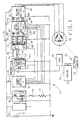
- the reference numeral 10 generally designates an automotive electrical apparatus including a storage battery 12 and a plurality of switched electrical loads symbolized by the resistor 14 and the series switch 16.
- the automotive electrical apparatus 10 additionally includes a (3-phase) induction machine 18, which is selectively operated in a motoring mode for cranking an internal combustion engine 20 (hereinafter referred to as an engine), or a generating mode for supplying electrical current to the storage battery 12 and electrical loads 14.
- the engine 20 is mechanically coupled to the induction machine 18 by the combination of a belt drive 22 and a bimodal planetary drive 24, described below in reference to Figure 2.
- the control circuit for governing the operation of the above-described components is designated generally by the reference numeral 25.
- the battery voltage V b is supplied directly to bridge circuit 26 (bi-directional bridge circuit means), and via an ignition switch 28 to load converter 30, power supply 32, a (computer-based) SYSTEM CONTROL UNIT 34 and gate driver circuits 38. Regulated output voltages from power supply 32 are supplied to a (computer-based 3-phase) PWM GENERATOR 36, the gate driver circuit 38 and the SYSTEM CONTROL UNIT 34, as indicated.
- the battery voltage V b is controlled in relation to battery charging requirements, but the load converter 30 (illustrated as a conventional buck converter) supplies a lower, fixed output voltage to the electrical loads 14. Multiple load converter units may be employed for providing multiple load voltages if desired, as indicated by the block 30′.
- SYSTEM CONTROL UNIT 34 and PWM GENERATOR 36 define control means.
- the rotary speed of induction machine 18 is sensed by a pulse-type tachometer 40, such as the Hewlett Packard HEDS-5500.
- the tachometer output TACH is provided as an input to SYSTEM CONTROL UNIT 34 along with the battery voltage V b , an ON/OFF input and a START (ST) input.
- the ON/0FF input enables/disables circuit operation and the START input enables initiation of engine cranking.
- the SYSTEM CONTROL UNIT 34 determines whether the motoring or generating mode is appropriate, determines the desired excitation and slip, and outputs amplitude and power frequency control signals A, POWERF to PWM GENERATOR 36 on lines 42 and 44, respectively.
- the excitation is ramped up to an optimum level for motoring for smooth quiet starting of the engine 20.
- the excitation amplitude is ramped up to an optimum generating level for a smooth transition between starting and generating.
- the power frequency is computed according to the sum of the machine rotor speed ROTORSPD and a slip command SLPCMD determined in relation to the amount by which the actual battery voltage V b differs from a desired voltage reference.
- the SYSTEM CONTROL UNIT 34 comprises a number of conventional devices including an input/output device I/O, a timer/counter device TMR/CTR and a microcomputer ⁇ C, all of which are connected to a bus 52.
- the I/O device receives the ON/OFF, ST and V b inputs and generates the machine amplitude control signal A.
- the TMR/CTR device operates as an input counter for the TACH signal and as an output counter for the PWMPER output.
- the TMR/CTR also performs a loop timing function as indicated by the line 54 and as described below.
- Flow diagrams representative of the program instructions executed by the microcomputer ⁇ C in carrying out the control functions referred to above are set forth in Figures 4, 5a, 5b and 6.
- the PWM GENERATOR 36 executes a sine function look-up, and provides six low level (5-volt) PWM drive signals to the gate driver circuit 38 on lines 56 - 66 in accordance with the excitation amplitude and power frequency control signals A, POWERF supplied by the SYSTEM CONTROL UNIT 34.
- the PWM GENERATOR 36 comprises a number of conventional devices including a microcomputer °C, three PWM driver devices PWM1, PWM2, PWM3 and a clock C.
- the PWM1 driver generates the drive signals for the upper and lower switching devices of Phase 1 on lines 56 and 58; the PWM2 driver generates the drive signals for the upper and lower switching devices of Phase 2 on lines 60 and 62; and the PWM3 driver generates the drive signals for the upper and lower switching devices of Phase 3 on lines 64 and 66.
- the PWM pulse width commands are supplied from the microcomputer ⁇ C to the PWM drivers PWM1, PWM2, PWM3 via data bus 68 and device select and handshake line 70.
- the clock C supplies the PWM drivers with a high frequency clock signal for resolving the PWM pulse width commands.
- the gate driver circuits 38 convert the low level PWM drive signals on lines 56 - 66 to isolated high level (16-volt) signals on lines 72 - 82 for driving the switching devices of bridge circuit 26.
- Bridge circuit 26 is configured for 3-phase full-wave current control of the induction machine 18. In the cranking mode, it excites the 3-phase windings of induction machine 18 with sinusoidal current of the desired amplitude and frequency from storage battery 12. In the generating mode, it draws sinusoidal load current of the desired amplitude and frequency from induction machine 18.
- induction machine 18 and bimodal planetary drive 24 are depicted in greater detail in Figure 2.
- induction machine housing 90 and bimodal drive housing 92 are joined at 94 and adapted to be mounted to engine 20 at the flange 96.
- the bimodal planetary drive 24 could be driven directly by the engine crankshaft.
- the induction machine housing 90 supports the stator windings and laminations 98, 100 of induction machine 18, and the bimodal drive housing 92 supports a ring gear 102 of bimodal planetary drive 24.
- the outboard end of machine rotor 104 is rotatably supported by the induction machine housing 90 on a ball bearing 106 and drives the pulse-type tachometer 40 which is mounted on the outboard end of induction machine housing 90 as shown.
- the inboard end of machine rotor 104 is rotatably supported within an output shaft 108 on a sleeve bearing 109 and a one-way clutch 110.
- the inboard end of output shaft 108 is rotatably supported by a two-stage planetary gearset 112 on a sleeve bearing 114 and a one-way clutch 116, and the outboard end of output shaft 108 is rotatably supported by a ball bearing 118 mounted in the bimodal drive housing 92.
- the two-stable planetary gearset 112 and one-way clutches 110, 116 serve to mechanically couple the machine rotor 104 and the output shaft 108.
- the output shaft 108 is coupled to the engine crankshaft via a 3:1 belt drive 22, as indicated in Figure 1.
- a sun gear 120 pressed onto an intermediate portion of the machine shaft 104 meshes with planet gears 122, which in turn mesh with a ring gear 124 mounted on the inner circumference of bimodal drive housing 92.
- a planet carrier 126 and integral sun gear 128 is supported on the output shaft 108 via the sleeve bearing 114.
- the sun gear 128 meshes with planet gears 130, which in turn mesh with the ring gear 102.
- a planet carrier 132 is coupled to the output shaft 108 via the one-way clutch 116.
- a sleeve bearing 134 supports the planet carrier 132 with respect to the bimodal drive housing 92.
- the induction machine 18 In engine cranking, the induction machine 18 is operated as a motor, and the bimodal planetary drive 24 establishes a 10:1 reduction ratio between the machine rotor and output shafts 104, 108. In this condition, the two-stage planetary gearset 112 is coupled to the output shaft 108 via one-way clutch 116 and the one-way clutch 110 overruns.
- the output shaft 108 drives the machine rotor 104 directly via one-way clutch 110 and the one-way clutch 116 overruns.
- the induction machine 18 is operated as a generator for producing electrical energy for battery charging and load energization.
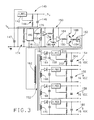
- the power supply 32 of Figure 1 is depicted in detail in Figure 3. As indicated in Figure 1, the power supply 32 generates a source of 5 volts DC (5 VDC) for the SYSTEM CONTROL UNIT 34 and PWM GENERATOR 36, and four isolated sources of 16 volts DC (16 VDC) for the gate driver circuits 38, using the battery voltage V b .
- 5 VDC 5 volts DC
- the 5 VDC power supply circuit designated by the reference numeral 140, is defined simply by voltage regulator 142, resistive voltage divider 144 and output filter capacitor 146.
- the battery voltage V b filtered by capacitor 147, is supplied as the input voltage to voltage regulator 142.
- the 16 VDC power supply circuits comprise an oscillator circuit 150, a transformer 152 and four isolated voltage regulator circuits 154, 156, 158, 160.
- the oscillator circuit 150 drives primary winding 162 of transformer 152, and each voltage regulator circuit 154, 156, 158, 160 is supplied by a transformer secondary winding 164, 166, 168, 170.
- the oscillator circuit 150 is built around a timer/oscillator chip 172 (such as the LM555 or equivalent) and associated RC elements 174 which generate a square-wave output of approximately 50 kHz on line 176.
- the square-wave output is applied to the inverting input of comparator 178 via resistor 180.
- the inverting comparator input is supplied with an offset reference voltage generated by resistive voltage divider 182.
- the output of comparator 178 is applied as an input to buffer amplifier 184 via a voltage limiting network 186, and the buffer amplifier output, in turn, is applied as an input to transistor driver pair 188 via resistor 190.
- the emitters of the transistors defining the driver pair 188 are joined and connected as an input to power FET 192 via resistor 194, the source-drain circuit of which is connected in series with the primary winding 162.
- the above-described elements operate to drive the primary winding 162 with alternating current at the oscillator output frequency of 50 kHz.
- the voltage regulator circuits 154, 156, 158, 160 are identical.
- the turn ratio of each secondary winding 164, 166, 168, 170 with respect to the primary winding 162 is chosen to develop an output voltage of 16 volts DC.
- each voltage regulator circuit comprises a diode rectifier 196 connected in series with the respective secondary winding 164, a filter capacitor 198, a voltage regulator 200 with resistive divider 202 and an output filter capacitor 204.
- the transformer 152 provides isolation between each of the 16 VDC voltage regulator circuits 154, 156, 158, 160.
- the various 16 VDC output voltages are designated herein as A+, A-, B+, B-, C+, C-, D+ and D-.
- FIG. 4 Flow diagrams representative of the program instructions executed by the microcomputer ⁇ C of SYSTEM CONTROL UNIT 34 in carrying out the functions referred to above are depicted in Figures 4, 5a, 5b and 6.
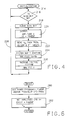
- the flow diagram of Figure 4 depicts a main loop or executive program which reads input values, generates outputs and commands the execution of various routines.
- the flow diagram of Figures 5a and 5b represent a SYSTEM SUPERVISOR routine and the flow diagram of Figure 6 represents a MACHINE CONTROL routine.
- the reference numeral 214 designates a series of instructions executed at the initiation of each period of vehicle operation for initializing the various registers, timers, flags and variables to an initial condition. Thereafter, the decision block 216 is executed to determine if the SCAN bit is set.
- the SCAN bit refers to an input latch of the SYSTEM CONTROL UNIT 34 TMR/CTR device which receives the low frequency (10 Hz) scan pulses on line 54. The SCAN bit is set on each rising edge of a scan pulse, signaling another execution of the main loop program.
- the instruction blocks 218 - 226 are executed to clear the SCAN bit, to output the most recent amplitude and power frequency values A, POWERF, to read new input values and to execute the SYSTEM SUPERVISOR and MACHINE CONTROL routines.
- the amplitude control signal A is generated in the form of an eight-bit word
- the power frequency control signal POWERF is generated by TMR/CTR in the form of a square wave having a frequency of sixteen times the desired power frequency.
- the factor of sixteen is used to facilitate operation of sixteen segment sinusoidal gate drive signals by the PWM GENERATOR 36, as described below. The above process is then repeated, as indicated by the flow return line 228.
- the decision block 230 is first executed to determine if the ON/OFF input is set to ON. If not, the instruction block 232 is executed to set the OFF MODE FLAG and the flow diagram portion 234 is executed to set up the OFF mode conditions and to determine if a transition to the motoring mode is appropriate. Instruction block 235 sets the excitation term EXCIT and the slip command SLIP CMD to zero.
- instruction block 240 is executed to set the MOTOR TRANSITION MODE FLAG so that a transition to the motoring mode of induction machine 18 will occur in the next execution of the SYSTEM SUPERVISOR routine. If the decision block 230 determines that the ON/OFF bit is set and decision block 242 determines that the OFF MODE FLAG is also set, the flow diagram portion 234 is executed as described above to determine if transition to the motoring mode is appropriate.
- the decision block 244 is executed to determine if the MOTOR TRANSITION FLAG is set. If so, the flow diagram portion 246 is executed to set up the motor transition conditions and to ramp up the machine excitation to a value of 0.6 volts/Hz. Thus, the instruction block 248 sets the machine slip command to 30 Hz and increments the excitation variable EXCIT from its initial zero value. When the excitation value reaches 0.6 volts/Hz as determined at decision block 250, the instruction block 252 is executed to clear the MOTOR TRANSITION MODE FLAG and to set the MOTOR MODE FLAG.
- decision block 244 is answered in the negative and decision block 254 is answered in the affirmative.
- flow diagram portion 256 is executed to set up the motoring conditions and to determine if a transition to the generate mode is appropriate.
- instruction block 258 sets the slip command to 30 Hz and the excitation EXCIT to 0.6 volts/Hz
- decision block 260 determines if the TACH frequency signal from pulse-type tachometer 40 is greater than a reference frequency START REF characteristic of engine starting.
- decision block 260 will be answered in the affirmative and instruction block 262 executed to set the slip command and excitation terms to zero, to clear the MOTOR MODE FLAG and to set the GENERATE TRANSITION MODE FLAG.
- the decision block 254 is answered in the negative and decision block 264 is answered in the affirmative.
- the flow diagram portion 266 is executed to ramp up the machine excitation to the normal generating mode value.
- instruction block 268 is executed to increment the excitation term EXCIT and the instruction block 274 is executed to set the slip command in relation to the difference between the actual battery voltage V b and the desired battery voltage V ref .
- instruction block 272 is executed to clear the GENERATE TRANSITION MODE FLAG to set the GENERATE MODE FLAG.
- instruction blocks 280 and 282 are executed to compute the power frequency POWERF and amplitude A control signals in accordance with the excitation and slip command terms determined by the SYSTEM SUPERVISOR routine.
- the power frequency term POWERF is determined to the sum of the rotor frequency from pulse-type tachometer 40 and the slip command frequency determined by the SYSTEM SUPERVISOR routine.
- the amplitude control signal A is determined to the product of the power frequency POWERF and the excitation term EXCIT determined by the SYSTEM SUPERVISOR routine, divided by the battery voltage V b . This results in a dimensionless fractional number which has a minimum value of zero and a maximum value of unity.
- FIG. 7 The flow diagrams of Figure 7 is representative of the computer program instructions executed by the microcomputer ⁇ C of the PWM GENERATOR 36.
- the PWM GENERATOR 36 operates in response to the power frequency and amplitude POWERF, A control signals from the SYSTEM CONTROL UNIT 34 to generate the six PWM drive signals on lines 56 - 66. Execution of the routine is triggered by a leading edge transition of the power frequency control signal POWERF, as indicated by decision block 290.
- the flow diagram of Figure 7 is executed 16 times per period of the power frequency. This effectively divides the period of the power frequency into sixteen increments of 22.5 electrical degrees. For each such increment, the PWM GENERATOR 36 outputs 3-phase PWM duty cycle commands to the PWM drivers PWM1, PWM2, PWM3 according to the product of the amplitude control signal A and a sine function look-up. The PWM driver outputs, in turn, control the switching devices of the bridge circuit 26 to produce sinusoidal three-phase power voltages and currents in the stator windings of induction machine 18.
- the frequency command increments a sixteen count counter (COUNT).
- COUNT sixteen count counter
- the sine function look-up in turn, generates sine factors for the three machine phases SIN1, SIN2, SIN3 based on the COUNT value. Representative sine factors and the corresponding COUNT value are depicted in the chart of Figure 8.
- a duty cycle offset of 50 percent is employed since zero excitation of the machine occurs when all three phases are operating at a duty cycle of 50 percent.
- DUtY cycles greater than 50 percent produce a positive output voltage; duty cycles less than 50 percent produce a negative output voltage.
- the three-phase PWM duty cycles for a complete cycle of the power frequency POWERF are graphically depicted in Figure 9.
- instruction blocks 292 and 294 are first executed to read the amplitude term A and to increment the counter term COUNT.
- Instruction blocks 296 - 300 are then executed to look-up the phase-one sine factor SIN1 based on the value of COUNT, to compute an offset PWM duty cycle PWMDC1 and to store the computed duty cycle in a temporary register, REG1.
- the sine factors SIN2, SIN3 and PWM duty cycles PWMDC2, PWMDC3 are similarly determined, as indicated at instruction blocks 302 - 306 and 308 - 312, respectively.
- instruction block 314 is executed to output the stored duty cycle values PWMDC1, PWMDC2, PWMDC3 to the PWM drivers PWM1, PWM2, PWM3.
- the PWM drivers PWM1, PWM2, PWM3 each generate two complementary PWM signals -- one for the high side switching device and one for the low side switching device.
- the on-time for the high side switching device is equal to the product of the commanded duty cycle (PWMDC) and the period of the switching frequency (1/20 kHz).
- each gate driver circuit includes an input buffer 320, a level shifter 322 and six isolated driver circuits 324 - 334.
- the level shifter 322 comprises six comparators 336 - 346, each of which receives a low level (5-volt) PWM input and a high level reference voltage developed form battery voltage V b by divider resistors 348 and 350.
- the resulting high level (12/24 volt) PWM outputs on lines 352 - 362 are maintained normally high by pull-up resistors 364 - 374 and are connected as inputs to the driver circuits 324 - 334, respectively.
- the six driver circuit outputs on lines 72 - 82 are supplied as control inputs to the power devices of the bridge circuit 26 for controlling their conduction.
- Isolated driver circuits 324-334 are provided for the high side power devices since the bridge circuit 26 is comprised of all N-channel power devices.
- the high-side driver circuits 324, 328 and 332 are each provided with an isolated 16 VDC source from power supply 32, as indicated by the designations A+, A-, B+, B-, C+ and C-.
- the low-side driver circuits 326, 330 and 334 are provided with the same 16 VDC source, as indicated by the designations D+ and D-. Accordingly, it will be understood that the circuits in each of blocks 376, 378 and 380 are identical except for input and power supply origin.
- a representative PWM driver circuit (block 376) is shown in detail in Figure 11.
- the high level PWM inputs on lines 352 and 354 are supplied to the driver circuits 324 and 326, respectively, and the respective driver outputs are generated on lines 72 and 74.
- An optical coupler circuit 382 and associated elements 384 are used to reference the high-side PWM input on line 352 to the A+, A- power supply.
- the D- power supply line for the low-side driver circuit 326 is referenced to battery ground potential, as indicated.
- the optically isolated high-side PWM driver output on line 386 is supplied as an input to comparator 388, along with a reference voltage determined by divider resistors 390, 392 and capacitor 394.
- the comparator 388 and resistors 396, 398 bias transistor 400 on and off in accordance with the PWM driver output.
- the transistor 400 biases output transistor pair 402 on and off via the resistors 404, 406.
- the emitters of the output transistor pair 402 are joined and connected to the (driver output) line 72.
- the high-side driver elements 388 - 406 are essentially repeated in the low-side driver circuit 326 and are not specifically described herein.
- the six driver circuit outputs on lines 72 - 82 are supplied as control inputs to the power devices of the bridge circuit 26, which is depicted in detail in Figure 12.
- the bridge circuit 26 comprises six power devices 420 - 430, each including an N-channel power FET 432 and associated transient protection devices 434, as designated within the power device 420.
- Bridge output terminals 436, 438, 440 are connected to the stator windings of induction machine 18 and the bridge circuit power devices 420 - 430 are pulse-width-modulated such that the induction machine 18 receives (motoring) sinusoidal current from the storage battery 12 or supplies (generating) rectified sinusoidal current for battery charging.
- the SYSTEM CONTROL UNIT 34 varies the excitation/loading during motoring start-up and transition between motoring and generating and ultimately operates the induction machine 18 substantially at its most efficient level.
- Figure 13 depicts the current generating characteristic of the automotive electrical apparatus of this invention (trace 500), compared to that of a conventionally controlled automotive generator (trace 502).
- current cannot normally be supplied to the 13-volt battery load until the generator speed is sufficiently high to produce at least 13 volts; this is referred to as the cut-in voltage/speed.
- the current generating capability is limited by the stator impedance and ultimately cannot exceed a limit value corresponding to the saturation limit of the machine.
- the boost capability of the bridge circuit 26 permits current to be drawn from the induction machine 18 at relatively low speeds. This avoids the limitations due to stator impedance and results in a increased generating capability at lower generator speeds, as indicated by the shaded area 504.
Landscapes
- Engineering & Computer Science (AREA)
- Power Engineering (AREA)
- Chemical & Material Sciences (AREA)
- Combustion & Propulsion (AREA)
- Mechanical Engineering (AREA)
- General Engineering & Computer Science (AREA)
- Transportation (AREA)
- Control Of Eletrric Generators (AREA)
- Control Of Charge By Means Of Generators (AREA)
Abstract
Description
- This invention pertains to an automotive electrical apparatus employing a single electrical machine for both starting and generating functions, and more particularly to such apparatus in which the single electrical machine is an induction machine.
- Conventional electrical apparatus for automobiles employing internal combustion engines, generally include one electrical machine (cranking motor) operated as a motor for cranking the engine during starting, and a separate electrical machine (generator/alternator) for generating electricity during operation of the engine.
- Over the years, various arrangements have been proposed for performing both starting and generating functions with a single electrical machine, but such arrangements generally suffer from compromised performance or greatly increased complexity, as compared to the arrangements they replace. Moreover, such arrangements typically do not address the problem of load voltage variation.
- An automotive electrical apparatus in accordance with the present invention is characterised by the features specified in the characterising portion of
claim 1. - The present invention is directed to a high efficiency automotive electrical apparatus and method of control employing an asynchronous induction machine for performing both starting and generating functions. The induction machine is coupled to the engine through a bimodal gearset for bi-directional mechanical energy exchange. The bimodal planetary drive operates as a reduction drive during the starting mode and as a direct drive during the generating mode. A bi-directional multi-phase bridge circuit couples the induction machine to the vehicle storage battery for bi-directional electrical energy exchange, and a load converter couples the storage battery to the vehicle electrical loads for energizing the electrical loads with current at predefined, steady voltages.
- A computer-based controller adjusts the machine excitation amplitude and frequency through the bi-directional bridge circuit to optimize the machine operating efficiency at the desired output level. Another computer-based controller schedules the desired output of the induction machine as a function of various parameters, including battery state of charge and the engine operating mode.
- The present invention will now be described, by way of example, with reference to the accompanying drawings, in which:-
- Figure 1 is a block diagram of an automotive electrical apparatus configured according to the present invention, including a (computer-based) SYSTEM CONTROL UNIT, a (computer-based) PWM GENERATOR, an induction machine and a bimodal planetary drive coupling the induction machine to the engine;
- Figure 2 is a schematic representation of the induction machine and bimodal planetary drive of Fiqure 1;
- Figures 3, 10, 11 and 12 depict circuit diagrams for various blocks set forth in Fiqure 1;
- Figures 4, 5a, 5b, and 6 depict flow diagrams representative of computer program instructions executed by the SYSTEM CONTROL UNIT of Figure 1;
- Figure 7 depicts a flow diagram representative of computer program instructions executed by the PWM GENERATOR of Figure 1;
- Figures 8 and 9 depict data used by the PWM GENERATOR of Figure 1 in scheduling the motor voltage waveforms; and
- Figure 13 is a graph depicting the increased generating capacity of the apparatus of this invention, as compared to a conventionally controlled generator.
- Referring now particularly to Figure 1, the
reference numeral 10 generally designates an automotive electrical apparatus including astorage battery 12 and a plurality of switched electrical loads symbolized by theresistor 14 and theseries switch 16. The automotiveelectrical apparatus 10 additionally includes a (3-phase)induction machine 18, which is selectively operated in a motoring mode for cranking an internal combustion engine 20 (hereinafter referred to as an engine), or a generating mode for supplying electrical current to thestorage battery 12 andelectrical loads 14. To this end, theengine 20 is mechanically coupled to theinduction machine 18 by the combination of abelt drive 22 and a bimodalplanetary drive 24, described below in reference to Figure 2. - The control circuit for governing the operation of the above-described components is designated generally by the
reference numeral 25. The battery voltage Vb is supplied directly to bridge circuit 26 (bi-directional bridge circuit means), and via anignition switch 28 to loadconverter 30,power supply 32, a (computer-based) SYSTEM CONTROL UNIT 34 andgate driver circuits 38. Regulated output voltages frompower supply 32 are supplied to a (computer-based 3-phase)PWM GENERATOR 36, thegate driver circuit 38 and the SYSTEM CONTROL UNIT 34, as indicated. As described below, the battery voltage Vb is controlled in relation to battery charging requirements, but the load converter 30 (illustrated as a conventional buck converter) supplies a lower, fixed output voltage to theelectrical loads 14. Multiple load converter units may be employed for providing multiple load voltages if desired, as indicated by theblock 30′. SYSTEM CONTROL UNIT 34 and PWMGENERATOR 36 define control means. - The rotary speed of
induction machine 18 is sensed by a pulse-type tachometer 40, such as the Hewlett Packard HEDS-5500. The tachometer output TACH is provided as an input toSYSTEM CONTROL UNIT 34 along with the battery voltage Vb, an ON/OFF input and a START (ST) input. The ON/0FF input enables/disables circuit operation and the START input enables initiation of engine cranking. - In response to the above inputs, the SYSTEM CONTROL UNIT 34 determines whether the motoring or generating mode is appropriate, determines the desired excitation and slip, and outputs amplitude and power frequency control signals A, POWERF to PWM GENERATOR 36 on
lines - In the cranking mode, the excitation is ramped up to an optimum level for motoring for smooth quiet starting of the
engine 20. Once theengine 20 has started and the generating mode is engaged, the excitation amplitude is ramped up to an optimum generating level for a smooth transition between starting and generating. In this mode, the power frequency is computed according to the sum of the machine rotor speed ROTORSPD and a slip command SLPCMD determined in relation to the amount by which the actual battery voltage Vb differs from a desired voltage reference. - Internally, the SYSTEM CONTROL UNIT 34 comprises a number of conventional devices including an input/output device I/O, a timer/counter device TMR/CTR and a microcomputer µC, all of which are connected to a
bus 52. The I/O device receives the ON/OFF, ST and Vb inputs and generates the machine amplitude control signal A. The TMR/CTR device operates as an input counter for the TACH signal and as an output counter for the PWMPER output. The TMR/CTR also performs a loop timing function as indicated by theline 54 and as described below. Flow diagrams representative of the program instructions executed by the microcomputer µC in carrying out the control functions referred to above are set forth in Figures 4, 5a, 5b and 6. - The PWM
GENERATOR 36 executes a sine function look-up, and provides six low level (5-volt) PWM drive signals to thegate driver circuit 38 on lines 56 - 66 in accordance with the excitation amplitude and power frequency control signals A, POWERF supplied by the SYSTEM CONTROL UNIT 34. Internally, the PWMGENERATOR 36 comprises a number of conventional devices including a microcomputer °C, three PWM driver devices PWM1, PWM2, PWM3 and a clock C. The PWM1 driver generates the drive signals for the upper and lower switching devices ofPhase 1 onlines Phase 2 onlines Phase 3 onlines data bus 68 and device select andhandshake line 70. The clock C supplies the PWM drivers with a high frequency clock signal for resolving the PWM pulse width commands. Flow diagrams representative of the program instructions executed by the microcomputer µC in carrying out the control functions referred to above are set forth in Figure 7. - The
gate driver circuits 38 convert the low level PWM drive signals on lines 56 - 66 to isolated high level (16-volt) signals on lines 72 - 82 for driving the switching devices ofbridge circuit 26. -
Bridge circuit 26 is configured for 3-phase full-wave current control of theinduction machine 18. In the cranking mode, it excites the 3-phase windings ofinduction machine 18 with sinusoidal current of the desired amplitude and frequency fromstorage battery 12. In the generating mode, it draws sinusoidal load current of the desired amplitude and frequency frominduction machine 18. - The
induction machine 18 and bimodalplanetary drive 24 are depicted in greater detail in Figure 2. As seen in that Figure, induction machine housing 90 andbimodal drive housing 92 are joined at 94 and adapted to be mounted toengine 20 at theflange 96. Alternately, the bimodalplanetary drive 24 could be driven directly by the engine crankshaft. Theinduction machine housing 90 supports the stator windings andlaminations induction machine 18, and thebimodal drive housing 92 supports aring gear 102 of bimodalplanetary drive 24. The outboard end ofmachine rotor 104 is rotatably supported by theinduction machine housing 90 on a ball bearing 106 and drives the pulse-type tachometer 40 which is mounted on the outboard end ofinduction machine housing 90 as shown. The inboard end ofmachine rotor 104 is rotatably supported within anoutput shaft 108 on a sleeve bearing 109 and a one-way clutch 110. The inboard end ofoutput shaft 108 is rotatably supported by a two-stageplanetary gearset 112 on a sleeve bearing 114 and a one-way clutch 116, and the outboard end ofoutput shaft 108 is rotatably supported by a ball bearing 118 mounted in thebimodal drive housing 92. - The two-stable
planetary gearset 112 and one-way clutches machine rotor 104 and theoutput shaft 108. Theoutput shaft 108 is coupled to the engine crankshaft via a 3:1belt drive 22, as indicated in Figure 1. Asun gear 120 pressed onto an intermediate portion of themachine shaft 104 meshes withplanet gears 122, which in turn mesh with aring gear 124 mounted on the inner circumference ofbimodal drive housing 92. Aplanet carrier 126 andintegral sun gear 128 is supported on theoutput shaft 108 via the sleeve bearing 114. Thesun gear 128 meshes withplanet gears 130, which in turn mesh with thering gear 102. Aplanet carrier 132 is coupled to theoutput shaft 108 via the one-way clutch 116. A sleeve bearing 134 supports theplanet carrier 132 with respect to thebimodal drive housing 92. - In engine cranking, the
induction machine 18 is operated as a motor, and the bimodalplanetary drive 24 establishes a 10:1 reduction ratio between the machine rotor andoutput shafts planetary gearset 112 is coupled to theoutput shaft 108 via one-way clutch 116 and the one-way clutch 110 overruns. - Once the
engine 20 has started, theoutput shaft 108 drives themachine rotor 104 directly via one-way clutch 110 and the one-way clutch 116 overruns. At such point, theinduction machine 18 is operated as a generator for producing electrical energy for battery charging and load energization. - The
power supply 32 of Figure 1 is depicted in detail in Figure 3. As indicated in Figure 1, thepower supply 32 generates a source of 5 volts DC (5 VDC) for theSYSTEM CONTROL UNIT 34 andPWM GENERATOR 36, and four isolated sources of 16 volts DC (16 VDC) for thegate driver circuits 38, using the battery voltage Vb. - The 5 VDC power supply circuit, designated by the
reference numeral 140, is defined simply byvoltage regulator 142,resistive voltage divider 144 andoutput filter capacitor 146. The battery voltage Vb, filtered bycapacitor 147, is supplied as the input voltage tovoltage regulator 142. - The 16 VDC power supply circuits comprise an
oscillator circuit 150, atransformer 152 and four isolatedvoltage regulator circuits oscillator circuit 150 drives primary winding 162 oftransformer 152, and eachvoltage regulator circuit - The
oscillator circuit 150 is built around a timer/oscillator chip 172 (such as the LM555 or equivalent) and associatedRC elements 174 which generate a square-wave output of approximately 50 kHz online 176. The square-wave output is applied to the inverting input ofcomparator 178 via resistor 180. The inverting comparator input is supplied with an offset reference voltage generated byresistive voltage divider 182. The output ofcomparator 178 is applied as an input tobuffer amplifier 184 via avoltage limiting network 186, and the buffer amplifier output, in turn, is applied as an input totransistor driver pair 188 viaresistor 190. The emitters of the transistors defining thedriver pair 188 are joined and connected as an input topower FET 192 viaresistor 194, the source-drain circuit of which is connected in series with the primary winding 162. Thus connected, the above-described elements operate to drive the primary winding 162 with alternating current at the oscillator output frequency of 50 kHz. - The
voltage regulator circuits voltage regulator circuit 154, it will be seen that each voltage regulator circuit comprises adiode rectifier 196 connected in series with the respective secondary winding 164, afilter capacitor 198, avoltage regulator 200 withresistive divider 202 and anoutput filter capacitor 204. As indicated above, thetransformer 152 provides isolation between each of the 16 VDCvoltage regulator circuits - Flow diagrams representative of the program instructions executed by the microcomputer µC of
SYSTEM CONTROL UNIT 34 in carrying out the functions referred to above are depicted in Figures 4, 5a, 5b and 6. The flow diagram of Figure 4 depicts a main loop or executive program which reads input values, generates outputs and commands the execution of various routines. The flow diagram of Figures 5a and 5b represent a SYSTEM SUPERVISOR routine and the flow diagram of Figure 6 represents a MACHINE CONTROL routine. - Referring to the main loop flow diagram of Figure 4, the
reference numeral 214 designates a series of instructions executed at the initiation of each period of vehicle operation for initializing the various registers, timers, flags and variables to an initial condition. Thereafter, thedecision block 216 is executed to determine if the SCAN bit is set. The SCAN bit refers to an input latch of theSYSTEM CONTROL UNIT 34 TMR/CTR device which receives the low frequency (10 Hz) scan pulses online 54. The SCAN bit is set on each rising edge of a scan pulse, signaling another execution of the main loop program. As soon as the SCAN bit is set, the instruction blocks 218 - 226 are executed to clear the SCAN bit, to output the most recent amplitude and power frequency values A, POWERF, to read new input values and to execute the SYSTEM SUPERVISOR and MACHINE CONTROL routines. The amplitude control signal A is generated in the form of an eight-bit word, and the power frequency control signal POWERF is generated by TMR/CTR in the form of a square wave having a frequency of sixteen times the desired power frequency. The factor of sixteen is used to facilitate operation of sixteen segment sinusoidal gate drive signals by thePWM GENERATOR 36, as described below. The above process is then repeated, as indicated by theflow return line 228. - Referring now to the SYSTEM SUPERVISOR routine flow diagrams of Figures 5a and 5b, the
decision block 230 is first executed to determine if the ON/OFF input is set to ON. If not, theinstruction block 232 is executed to set the OFF MODE FLAG and theflow diagram portion 234 is executed to set up the OFF mode conditions and to determine if a transition to the motoring mode is appropriate.Instruction block 235 sets the excitation term EXCIT and the slip command SLIP CMD to zero. However, if both the ON/OFF and START bits are set, as determined by decision blocks 236 and 238,instruction block 240 is executed to set the MOTOR TRANSITION MODE FLAG so that a transition to the motoring mode ofinduction machine 18 will occur in the next execution of the SYSTEM SUPERVISOR routine. If thedecision block 230 determines that the ON/OFF bit is set anddecision block 242 determines that the OFF MODE FLAG is also set, theflow diagram portion 234 is executed as described above to determine if transition to the motoring mode is appropriate. - If the ON/OFF bit is set and the OFF MODE FLAG is not set, the
decision block 244 is executed to determine if the MOTOR TRANSITION FLAG is set. If so, theflow diagram portion 246 is executed to set up the motor transition conditions and to ramp up the machine excitation to a value of 0.6 volts/Hz. Thus, theinstruction block 248 sets the machine slip command to 30 Hz and increments the excitation variable EXCIT from its initial zero value. When the excitation value reaches 0.6 volts/Hz as determined atdecision block 250, theinstruction block 252 is executed to clear the MOTOR TRANSITION MODE FLAG and to set the MOTOR MODE FLAG. - In the next execution of the SYSTEM SUPERVISOR routine following execution of the
instruction block 252, thedecision block 244 is answered in the negative anddecision block 254 is answered in the affirmative. At such point,flow diagram portion 256 is executed to set up the motoring conditions and to determine if a transition to the generate mode is appropriate. To this end,instruction block 258 sets the slip command to 30 Hz and the excitation EXCIT to 0.6 volts/Hz, anddecision block 260 determines if the TACH frequency signal from pulse-type tachometer 40 is greater than a reference frequency START REF characteristic of engine starting. When the engine starts,decision block 260 will be answered in the affirmative andinstruction block 262 executed to set the slip command and excitation terms to zero, to clear the MOTOR MODE FLAG and to set the GENERATE TRANSITION MODE FLAG. - In the next execution of the SYSTEM SUPERVISOR routine following the execution of
instruction block 262, thedecision block 254 is answered in the negative anddecision block 264 is answered in the affirmative. At such point, theflow diagram portion 266 is executed to ramp up the machine excitation to the normal generating mode value. To this end,instruction block 268 is executed to increment the excitation term EXCIT and theinstruction block 274 is executed to set the slip command in relation to the difference between the actual battery voltage Vb and the desired battery voltage Vref. Once the excitation EXCIT is increased to the nominal generating value of 0.3 volts/Hz, as determined bydecision block 270,instruction block 272 is executed to clear the GENERATE TRANSITION MODE FLAG to set the GENERATE MODE FLAG. - In the next execution of the SYSTEM SUPERVISOR routine following the execution of the
instruction block 272, thedecision block 264 will be answered in the negative and decision block 276 will be answered in the affirmative. At such point, the excitation term EXCIT is maintained at the value 0.3 volts/Hz and the slip command continues to be determined as a function of the battery voltage error as indicated atinstruction block 274. If thedecision block 276 is answered in the negative,instruction block 278 is executed to set the OFF MODE FLAG, completing the routine. - Referring now to the MACHINE CONTROL routine of Figure 6, instruction blocks 280 and 282 are executed to compute the power frequency POWERF and amplitude A control signals in accordance with the excitation and slip command terms determined by the SYSTEM SUPERVISOR routine. As indicated at
instruction block 280, the power frequency term POWERF is determined to the sum of the rotor frequency from pulse-type tachometer 40 and the slip command frequency determined by the SYSTEM SUPERVISOR routine. As indicated atinstruction block 282, the amplitude control signal A is determined to the product of the power frequency POWERF and the excitation term EXCIT determined by the SYSTEM SUPERVISOR routine, divided by the battery voltage Vb. This results in a dimensionless fractional number which has a minimum value of zero and a maximum value of unity. - The flow diagrams of Figure 7 is representative of the computer program instructions executed by the microcomputer µC of the
PWM GENERATOR 36. As indicated above, thePWM GENERATOR 36 operates in response to the power frequency and amplitude POWERF, A control signals from theSYSTEM CONTROL UNIT 34 to generate the six PWM drive signals on lines 56 - 66. Execution of the routine is triggered by a leading edge transition of the power frequency control signal POWERF, as indicated bydecision block 290. - Since the frequency command supplied to the
PWM GENERATOR 36 is 16 times the desired power frequency POWERF, the flow diagram of Figure 7 is executed 16 times per period of the power frequency. This effectively divides the period of the power frequency into sixteen increments of 22.5 electrical degrees. For each such increment, thePWM GENERATOR 36 outputs 3-phase PWM duty cycle commands to the PWM drivers PWM1, PWM2, PWM3 according to the product of the amplitude control signal A and a sine function look-up. The PWM driver outputs, in turn, control the switching devices of thebridge circuit 26 to produce sinusoidal three-phase power voltages and currents in the stator windings ofinduction machine 18. - The frequency command increments a sixteen count counter (COUNT). The sine function look-up, in turn, generates sine factors for the three machine phases SIN1, SIN2, SIN3 based on the COUNT value. Representative sine factors and the corresponding COUNT value are depicted in the chart of Figure 8.
- The PWM duty cycles PWMDC1, PWMDC2, PWMDC3 are then determined according to the expressions:
PWMDC1 = [(A * SIN1)/2] + 0.50
PWMDC2 = [(A * SIN2)/2] + 0.50
PWMDC3 = [(A * SIN3)/2] + 0.50
where the amplitude A and the respective sine factor SIN1, SIN2, SIN3 each vary between zero and one. A duty cycle offset of 50 percent is employed since zero excitation of the machine occurs when all three phases are operating at a duty cycle of 50 percent. DUtY cycles greater than 50 percent produce a positive output voltage; duty cycles less than 50 percent produce a negative output voltage. The three-phase PWM duty cycles for a complete cycle of the power frequency POWERF are graphically depicted in Figure 9. - Referring to the flow diagram, instruction blocks 292 and 294 are first executed to read the amplitude term A and to increment the counter term COUNT. Instruction blocks 296 - 300 are then executed to look-up the phase-one sine factor SIN1 based on the value of COUNT, to compute an offset PWM duty cycle PWMDC1 and to store the computed duty cycle in a temporary register, REG1. The sine factors SIN2, SIN3 and PWM duty cycles PWMDC2, PWMDC3 are similarly determined, as indicated at instruction blocks 302 - 306 and 308 - 312, respectively. Then,
instruction block 314 is executed to output the stored duty cycle values PWMDC1, PWMDC2, PWMDC3 to the PWM drivers PWM1, PWM2, PWM3. - As indicated above, the PWM drivers PWM1, PWM2, PWM3 each generate two complementary PWM signals -- one for the high side switching device and one for the low side switching device. In each case, the on-time for the high side switching device is equal to the product of the commanded duty cycle (PWMDC) and the period of the switching frequency (1/20 kHz).
- The six PWM driver outputs on lines 56 - 66 are supplied as inputs to the
gate driver circuit 38, which is depicted in detail in Figures 10 and 11. Referring to Figure 10, it is seen that each gate driver circuit includes aninput buffer 320, alevel shifter 322 and six isolated driver circuits 324 - 334. Thelevel shifter 322 comprises six comparators 336 - 346, each of which receives a low level (5-volt) PWM input and a high level reference voltage developed form battery voltage Vb bydivider resistors - The six driver circuit outputs on lines 72 - 82 are supplied as control inputs to the power devices of the
bridge circuit 26 for controlling their conduction. Isolated driver circuits 324-334 are provided for the high side power devices since thebridge circuit 26 is comprised of all N-channel power devices. Thus, the high-side driver circuits power supply 32, as indicated by the designations A+, A-, B+, B-, C+ and C-. The low-side driver circuits blocks - A representative PWM driver circuit (block 376) is shown in detail in Figure 11. Thus, the high level PWM inputs on
lines driver circuits lines optical coupler circuit 382 and associatedelements 384 are used to reference the high-side PWM input online 352 to the A+, A- power supply. The D- power supply line for the low-side driver circuit 326 is referenced to battery ground potential, as indicated. - The optically isolated high-side PWM driver output on
line 386 is supplied as an input tocomparator 388, along with a reference voltage determined bydivider resistors 390, 392 andcapacitor 394. Thecomparator 388 andresistors bias transistor 400 on and off in accordance with the PWM driver output. Thetransistor 400, in turn, biasesoutput transistor pair 402 on and off via theresistors output transistor pair 402 are joined and connected to the (driver output)line 72. The high-side driver elements 388 - 406 are essentially repeated in the low-side driver circuit 326 and are not specifically described herein. - As indicated above, the six driver circuit outputs on lines 72 - 82 are supplied as control inputs to the power devices of the
bridge circuit 26, which is depicted in detail in Figure 12. Referring to Figure 12, thebridge circuit 26 comprises six power devices 420 - 430, each including an N-channel power FET 432 and associatedtransient protection devices 434, as designated within thepower device 420. -
Bridge output terminals induction machine 18 and the bridge circuit power devices 420 - 430 are pulse-width-modulated such that theinduction machine 18 receives (motoring) sinusoidal current from thestorage battery 12 or supplies (generating) rectified sinusoidal current for battery charging. TheSYSTEM CONTROL UNIT 34 varies the excitation/loading during motoring start-up and transition between motoring and generating and ultimately operates theinduction machine 18 substantially at its most efficient level. - Figure 13 depicts the current generating characteristic of the automotive electrical apparatus of this invention (trace 500), compared to that of a conventionally controlled automotive generator (trace 502). In the conventional arrangement, current cannot normally be supplied to the 13-volt battery load until the generator speed is sufficiently high to produce at least 13 volts; this is referred to as the cut-in voltage/speed. Thereafter, the current generating capability is limited by the stator impedance and ultimately cannot exceed a limit value corresponding to the saturation limit of the machine. In the apparatus of this invention, however, the boost capability of the
bridge circuit 26 permits current to be drawn from theinduction machine 18 at relatively low speeds. This avoids the limitations due to stator impedance and results in a increased generating capability at lower generator speeds, as indicated by the shadedarea 504. - Alternative arrangements to the above include, for example, the functions of the
SYSTEM CONTROL UNIT 34 andPWM GENERATOR 36 being performed by a single computer-based controller.
Claims (6)
Applications Claiming Priority (2)
| Application Number | Priority Date | Filing Date | Title |
|---|---|---|---|
| US07/227,036 US4883973A (en) | 1988-08-01 | 1988-08-01 | Automotive electrical system having a starter/generator induction machine |
| US227036 | 1988-08-01 |
Publications (2)
| Publication Number | Publication Date |
|---|---|
| EP0357183A1 true EP0357183A1 (en) | 1990-03-07 |
| EP0357183B1 EP0357183B1 (en) | 1992-03-25 |
Family
ID=22851481
Family Applications (1)
| Application Number | Title | Priority Date | Filing Date |
|---|---|---|---|
| EP89306027A Expired - Lifetime EP0357183B1 (en) | 1988-08-01 | 1989-06-14 | Automotive electrical apparatus having a starter/generator induction machine |
Country Status (6)
| Country | Link |
|---|---|
| US (1) | US4883973A (en) |
| EP (1) | EP0357183B1 (en) |
| JP (1) | JP2650760B2 (en) |
| KR (1) | KR930001646B1 (en) |
| CA (1) | CA1301242C (en) |
| DE (1) | DE68901073D1 (en) |
Cited By (11)
| Publication number | Priority date | Publication date | Assignee | Title |
|---|---|---|---|---|
| EP0665637A1 (en) * | 1994-01-31 | 1995-08-02 | Nippondenso Co., Ltd. | Electric power generating device for vehicles |
| EP0693816A1 (en) * | 1994-07-19 | 1996-01-24 | Nippondenso Co., Ltd. | AC generator |
| DE19610915A1 (en) * | 1996-03-20 | 1997-09-25 | Wilhelm Wingensiefen | District heating power station for operating in existing electric power network |
| EP0903832A1 (en) * | 1997-01-13 | 1999-03-24 | Honda Giken Kogyo Kabushiki Kaisha | Generator for internal combustion engine |
| WO2000026532A1 (en) * | 1998-10-29 | 2000-05-11 | Robert Bosch Gmbh | Belt drive, especially for internal combustion engines, to drive accessories in an automobile |
| FR2791310A1 (en) * | 1999-03-26 | 2000-09-29 | Mannesmann Sachs Ag | Electric circuit lay-out for vehicles, comprises control and power modules rated for the normal demand of consuming units and means to switch two modules in parallel under high load conditions |
| WO2001011765A1 (en) * | 1999-08-04 | 2001-02-15 | Westerbeke Corporation | Controlling generator power |
| EP1122879A2 (en) * | 2000-01-31 | 2001-08-08 | Ecostar Electric Drive Systems L.L.C. | Method and apparatus for controlling rotary machine coupled to a turbo engine |
| WO2004006423A2 (en) | 2002-07-04 | 2004-01-15 | Valeo Equipements Electriques Moteur | Control and power module for integrated alternator-starter |
| FR2874764A1 (en) * | 2004-08-31 | 2006-03-03 | Valeo Equip Electr Moteur | CONTROL AND POWER MODULE FOR A ROTATING ELECTRIC MACHINE |
| RU2656240C1 (en) * | 2017-01-30 | 2018-06-04 | Александр Геннадьевич Ходырев | Electric propulsion unit for the free energy generation using the asynchronous slip generator |
Families Citing this family (59)
| Publication number | Priority date | Publication date | Assignee | Title |
|---|---|---|---|---|
| US5055700A (en) * | 1989-10-16 | 1991-10-08 | Dhyanchand P John | Brushless generator having prime mover start capability |
| US5281905A (en) * | 1989-12-14 | 1994-01-25 | Sundstrand Corporation | Induction machine based hybrid aircraft engine starting/generating power system |
| JP3083310B2 (en) * | 1990-01-26 | 2000-09-04 | 三菱電機株式会社 | Engine power transmission with start function |
| US5225764A (en) * | 1991-11-29 | 1993-07-06 | Sgs-Thomson Microelectronics, Inc. | Voltage regulating circuitry to vary the alternator field coil drive at a rate dependent upon a rotor velocity signal |
| JPH06225599A (en) * | 1992-10-14 | 1994-08-12 | Ford Motor Co | Output power controller of generator for car |
| JP3214224B2 (en) * | 1994-04-22 | 2001-10-02 | 株式会社日立製作所 | Vehicle generator |
| FI97654C (en) * | 1994-09-09 | 1997-01-27 | Abb Industry Oy | Procedure for starting an asynchronous machine |
| US5720690A (en) * | 1995-06-16 | 1998-02-24 | Aisin Aw Co., Ltd. | Shift control system for controlling a transmission of a vehicle having an engine and a motor generator drive source |
| US6148784A (en) * | 1995-08-31 | 2000-11-21 | Isad Electronic Systems Gmbh & Co. Kg | Drive systems, especially for a motor vehicle, and method of operating same |
| DE59608158D1 (en) | 1995-08-31 | 2001-12-13 | Isad Electronic Sys Gmbh & Co | DRIVE SLIP CONTROL SYSTEM FOR A MOTOR VEHICLE USING AN ELECTRIC MACHINE |
| US6177734B1 (en) * | 1998-02-27 | 2001-01-23 | Isad Electronic Systems Gmbh & Co. Kg | Starter/generator for an internal combustion engine, especially an engine of a motor vehicle |
| DE19532136A1 (en) * | 1995-08-31 | 1997-03-06 | Clouth Gummiwerke Ag | Drive system, in particular for a motor vehicle, and method for operating the same |
| DE19532135A1 (en) | 1995-08-31 | 1997-03-06 | Clouth Gummiwerke Ag | Drive system, in particular for a motor vehicle, and method for operating the same |
| US6158405A (en) * | 1995-08-31 | 2000-12-12 | Isad Electronic Systems | System for actively reducing rotational nonuniformity of a shaft, in particular, the drive shaft of an internal combustion engine, and method of operating the system |
| DE59603588D1 (en) * | 1995-08-31 | 1999-12-09 | Isad Electronic Sys Gmbh & Co | DRIVE SYSTEM WITH DRIVE MOTOR, ELECTRICAL MACHINE AND BATTERY |
| DE19532129A1 (en) | 1995-08-31 | 1997-03-06 | Clouth Gummiwerke Ag | System for actively reducing rotational irregularities of a shaft, in particular the drive shaft of an internal combustion engine, and method therefor |
| DE59606106D1 (en) * | 1995-08-31 | 2000-12-07 | Isad Electronic Sys Gmbh & Co | STARTER / GENERATOR FOR AN INTERNAL COMBUSTION ENGINE, ESPECIALLY A MOTOR VEHICLE |
| DE19532164A1 (en) | 1995-08-31 | 1997-03-06 | Clouth Gummiwerke Ag | Drive system, in particular for a motor vehicle, and method for operating the same |
| US5637987A (en) * | 1995-12-18 | 1997-06-10 | General Motors Corporation | Regenerative vehicle launch |
| FI963585A (en) * | 1996-09-11 | 1998-03-12 | Abb Industry Oy | Electrical System |
| DE19646043A1 (en) * | 1996-11-08 | 1998-05-14 | Bosch Gmbh Robert | Power supply device |
| FR2757325B1 (en) * | 1996-12-16 | 1999-03-05 | Valeo Equip Electr Moteur | METHOD FOR MANAGING THE EXCITATION OF A MOTOR VEHICLE ALTERNATOR BY A REGULATOR |
| US6784565B2 (en) | 1997-09-08 | 2004-08-31 | Capstone Turbine Corporation | Turbogenerator with electrical brake |
| US6487096B1 (en) | 1997-09-08 | 2002-11-26 | Capstone Turbine Corporation | Power controller |
| US5903116A (en) | 1997-09-08 | 1999-05-11 | Capstone Turbine Corporation | Turbogenerator/motor controller |
| US6870279B2 (en) | 1998-01-05 | 2005-03-22 | Capstone Turbine Corporation | Method and system for control of turbogenerator power and temperature |
| US20020166324A1 (en) | 1998-04-02 | 2002-11-14 | Capstone Turbine Corporation | Integrated turbine power generation system having low pressure supplemental catalytic reactor |
| US6079204A (en) * | 1998-09-21 | 2000-06-27 | Ford Global Technologies, Inc. | Torque control for direct injected engines using a supplemental torque apparatus |
| DE19927521C2 (en) * | 1998-11-14 | 2001-07-19 | Bosch Gmbh Robert | Electrical machine |
| US6612112B2 (en) | 1998-12-08 | 2003-09-02 | Capstone Turbine Corporation | Transient turbine exhaust temperature control for a turbogenerator |
| DE19910330A1 (en) * | 1999-03-09 | 2000-09-14 | Bayerische Motoren Werke Ag | Device for monitoring a starting device |
| US6232739B1 (en) | 2000-02-11 | 2001-05-15 | Delphi Technologies, Inc. | High-resolution incremental position sensor with pulse switching strategy |
| FR2806553B1 (en) * | 2000-03-17 | 2002-06-14 | Valeo Equip Electr Moteur | RECTIFIER FOR A POLYPHASE ALTERNATOR OF MOTOR VEHICLES WITH REDUCED ENERGY LOSSES |
| US6691507B1 (en) | 2000-10-16 | 2004-02-17 | Ford Global Technologies, Llc | Closed-loop temperature control for an emission control device |
| US6787933B2 (en) | 2001-01-10 | 2004-09-07 | Capstone Turbine Corporation | Power generation system having transient ride-through/load-leveling capabilities |
| US6603227B2 (en) | 2001-04-16 | 2003-08-05 | Briggs & Stratton Corporation | Small engine vehicle including a generator |
| US6777846B2 (en) | 2001-04-16 | 2004-08-17 | Briggs & Stratton Corporation | Vehicle including a three-phase generator |
| US8188718B2 (en) * | 2002-05-28 | 2012-05-29 | Advanced Battery Management, Llc | Method and apparatus for a remote battery charger with a self contained power source |
| US7989969B2 (en) | 2002-06-06 | 2011-08-02 | Black & Decker Inc. | Universal power tool battery pack coupled to a portable internal combustion engine |
| US8319357B2 (en) | 2002-06-06 | 2012-11-27 | Black & Decker Inc. | Starter system for portable internal combustion engine electric generators using a portable universal battery pack |
| EP1516421A2 (en) * | 2002-06-06 | 2005-03-23 | Black & Decker Inc. | Starter system for portable power unit using a portable universal battery pack |
| US7309928B2 (en) * | 2002-06-06 | 2007-12-18 | Black & Decker Inc. | Starter system for portable internal combustion engine electric generators using a portable universal battery pack |
| US7687926B2 (en) * | 2002-06-06 | 2010-03-30 | Black & Decker Inc. | Starter system for portable internal combustion engine electric generators using a portable universal battery pack |
| US20040085046A1 (en) * | 2002-11-01 | 2004-05-06 | General Electric Company | Power conditioning system for turbine motor/generator |
| US7353084B2 (en) * | 2003-02-27 | 2008-04-01 | Acutra, Inc. | Generator controller |
| US7161253B2 (en) * | 2003-08-06 | 2007-01-09 | Briggs & Stratton Corporation | Portable power source |
| AT504818A1 (en) | 2004-07-30 | 2008-08-15 | Windtec Consulting Gmbh | TRANSMISSION TRAIL OF A WIND POWER PLANT |
| US7224146B2 (en) * | 2005-10-06 | 2007-05-29 | Deere & Company | Dual voltage electrical system |
| US7782626B2 (en) | 2007-02-02 | 2010-08-24 | Black & Decker Inc. | Portable power driven system with battery anti-theft apparatus |
| KR100924924B1 (en) * | 2007-11-09 | 2009-11-05 | 주식회사 아모텍 | Gate driver and motor driving device using the same |
| AT508155B1 (en) * | 2009-05-25 | 2010-11-15 | Hehenberger Gerald Dipl Ing | ENERGY EQUIPMENT, IN PARTICULAR WIND POWER PLANT |
| RU2540416C2 (en) * | 2011-05-17 | 2015-02-10 | Хонда Мотор Ко., Лтд. | Inverter generator |
| JP2013103557A (en) * | 2011-11-11 | 2013-05-30 | Denso Corp | Power supply device |
| US20150051819A1 (en) * | 2013-08-14 | 2015-02-19 | Honda Motor Co., Ltd. | Systems and methods for controlling sound generated by a vehicle during vehicle start-up operations |
| DE102013216700B4 (en) * | 2013-08-22 | 2022-01-27 | Siemens Mobility GmbH | Charging battery-capable road vehicles |
| CN103501145B (en) * | 2013-09-16 | 2016-05-11 | 贵州电网公司电网规划研究中心 | Power grid high-frequency stability forecast control method based on lonely net trend principle of transfer |
| US10059189B2 (en) * | 2014-04-29 | 2018-08-28 | Cummins Inc. | Electric machine with variable torque drive |
| US10778123B2 (en) * | 2015-10-16 | 2020-09-15 | Kohler Co. | Synchronous inverter |
| EP3555993A4 (en) | 2016-11-23 | 2020-08-12 | Sedemac Mechatronics PVT Ltd | A system for controlling electrical power generated by a permanent magnet machine |
Citations (4)
| Publication number | Priority date | Publication date | Assignee | Title |
|---|---|---|---|---|
| GB2080053A (en) * | 1980-07-17 | 1982-01-27 | Sundstrand Corp | Electric generating systems |
| DE3113092A1 (en) * | 1981-04-01 | 1982-10-21 | Volkswagenwerk Ag, 3180 Wolfsburg | "CIRCUIT ARRANGEMENT FOR GENERATING A ROTATING FIELD FOR A THREE-PHASE SYNCHRONOUS MACHINE USING A FLYWHEEL STARTER FOR A VEHICLE INTERNAL COMBUSTION ENGINE" |
| US4401938A (en) * | 1980-12-29 | 1983-08-30 | Lockheed Corporation | Variable-speed drive for control of induction generators |
| EP0151935A1 (en) * | 1984-01-26 | 1985-08-21 | Institut Cerac S.A. | Starting device |
Family Cites Families (15)
| Publication number | Priority date | Publication date | Assignee | Title |
|---|---|---|---|---|
| US3908161A (en) * | 1974-02-07 | 1975-09-23 | Gen Electric | Field excitation system for synchronous machines utilizing a rotating transformer brushless exciter generating combination |
| US3937974A (en) * | 1974-08-30 | 1976-02-10 | General Electric Company | Starter-generator utilizing phase controlled rectifiers to drive a dynamoelectric machine as a brushless DC motor in the starting mode with starter position sense variation with speed |
| JPS56112897A (en) * | 1980-02-12 | 1981-09-05 | Toshiba Corp | Freezing device |
| JPS57145600A (en) * | 1981-03-02 | 1982-09-08 | Shinko Electric Co Ltd | Main shaft driving generating device |
| JPH0632595B2 (en) * | 1982-12-28 | 1994-04-27 | 富士電機株式会社 | Output control method of induction generator |
| JPS6062899U (en) * | 1983-10-05 | 1985-05-02 | 三洋電機株式会社 | Air conditioner power generation device |
| JPS60118095A (en) * | 1983-11-30 | 1985-06-25 | Nissan Motor Co Ltd | Control circuit of motor used as generator |
| US4481459A (en) * | 1983-12-20 | 1984-11-06 | Sundstrand Corporation | Combined starting/generating system and method |
| JPS60261399A (en) * | 1984-06-08 | 1985-12-24 | Hitachi Ltd | Operating method of induction generator |
| JPS6126500A (en) * | 1984-07-17 | 1986-02-05 | Hitachi Ltd | Integrated starter generator |
| JPS6149697A (en) * | 1984-08-14 | 1986-03-11 | Toshiba Corp | Wind power generator |
| US4786852A (en) * | 1986-07-18 | 1988-11-22 | Sundstrand Corporation | Inverter operated turbine engine starting system |
| US4743776A (en) * | 1986-09-02 | 1988-05-10 | Sundstrand Corporation | Starter-generator for engines |
| US4697090A (en) * | 1986-12-23 | 1987-09-29 | Sundstrand Corporation | Starting system for an electrically-compensated constant speed drive |
| US4777376A (en) * | 1987-12-18 | 1988-10-11 | Sundstrand Corporation | Lightweight starting system for an electrically compensated constant speed drive |
-
1988
- 1988-08-01 US US07/227,036 patent/US4883973A/en not_active Expired - Lifetime
-
1989
- 1989-05-18 CA CA000600035A patent/CA1301242C/en not_active Expired - Fee Related
- 1989-06-14 DE DE8989306027T patent/DE68901073D1/en not_active Expired - Lifetime
- 1989-06-14 EP EP89306027A patent/EP0357183B1/en not_active Expired - Lifetime
- 1989-07-26 JP JP1193812A patent/JP2650760B2/en not_active Expired - Lifetime
- 1989-08-01 KR KR1019890011007A patent/KR930001646B1/en not_active IP Right Cessation
Patent Citations (4)
| Publication number | Priority date | Publication date | Assignee | Title |
|---|---|---|---|---|
| GB2080053A (en) * | 1980-07-17 | 1982-01-27 | Sundstrand Corp | Electric generating systems |
| US4401938A (en) * | 1980-12-29 | 1983-08-30 | Lockheed Corporation | Variable-speed drive for control of induction generators |
| DE3113092A1 (en) * | 1981-04-01 | 1982-10-21 | Volkswagenwerk Ag, 3180 Wolfsburg | "CIRCUIT ARRANGEMENT FOR GENERATING A ROTATING FIELD FOR A THREE-PHASE SYNCHRONOUS MACHINE USING A FLYWHEEL STARTER FOR A VEHICLE INTERNAL COMBUSTION ENGINE" |
| EP0151935A1 (en) * | 1984-01-26 | 1985-08-21 | Institut Cerac S.A. | Starting device |
Cited By (21)
| Publication number | Priority date | Publication date | Assignee | Title |
|---|---|---|---|---|
| US5550457A (en) * | 1994-01-31 | 1996-08-27 | Nippondenso Co., Ltd. | Electric power generating device for vehicles |
| EP0665637A1 (en) * | 1994-01-31 | 1995-08-02 | Nippondenso Co., Ltd. | Electric power generating device for vehicles |
| EP0693816A1 (en) * | 1994-07-19 | 1996-01-24 | Nippondenso Co., Ltd. | AC generator |
| US5663631A (en) * | 1994-07-19 | 1997-09-02 | Nippondenso Co., Ltd. | Generator with circuitry for controlling power generation based on rotational speed |
| DE19610915A1 (en) * | 1996-03-20 | 1997-09-25 | Wilhelm Wingensiefen | District heating power station for operating in existing electric power network |
| EP0903832A1 (en) * | 1997-01-13 | 1999-03-24 | Honda Giken Kogyo Kabushiki Kaisha | Generator for internal combustion engine |
| EP0903832A4 (en) * | 1997-01-13 | 2000-10-04 | Honda Motor Co Ltd | Generator for internal combustion engine |
| WO2000026532A1 (en) * | 1998-10-29 | 2000-05-11 | Robert Bosch Gmbh | Belt drive, especially for internal combustion engines, to drive accessories in an automobile |
| FR2791310A1 (en) * | 1999-03-26 | 2000-09-29 | Mannesmann Sachs Ag | Electric circuit lay-out for vehicles, comprises control and power modules rated for the normal demand of consuming units and means to switch two modules in parallel under high load conditions |
| US6624533B1 (en) | 1999-08-04 | 2003-09-23 | Westerbeke Corporation | Controlling generator power |
| WO2001011765A1 (en) * | 1999-08-04 | 2001-02-15 | Westerbeke Corporation | Controlling generator power |
| EP1122879A2 (en) * | 2000-01-31 | 2001-08-08 | Ecostar Electric Drive Systems L.L.C. | Method and apparatus for controlling rotary machine coupled to a turbo engine |
| EP1122879A3 (en) * | 2000-01-31 | 2003-06-04 | Ecostar Electric Drive Systems L.L.C. | Method and apparatus for controlling rotary machine coupled to a turbo engine |
| WO2004006423A2 (en) | 2002-07-04 | 2004-01-15 | Valeo Equipements Electriques Moteur | Control and power module for integrated alternator-starter |
| WO2004006423A3 (en) * | 2002-07-04 | 2004-04-15 | Valeo Equip Electr Moteur | Control and power module for integrated alternator-starter |
| US7224145B2 (en) | 2002-07-04 | 2007-05-29 | Valeo Equipments Electriques Moteur | Control and power module for integrated alternator-starter |
| CN100347948C (en) * | 2002-07-04 | 2007-11-07 | 瓦莱奥电机设备公司 | Control and power module for integrated alternator-starter |
| FR2874764A1 (en) * | 2004-08-31 | 2006-03-03 | Valeo Equip Electr Moteur | CONTROL AND POWER MODULE FOR A ROTATING ELECTRIC MACHINE |
| WO2006027480A1 (en) * | 2004-08-31 | 2006-03-16 | Valeo Equipements Electriques Moteur | Control and power module for a rotating electric machine |
| US7560887B2 (en) | 2004-08-31 | 2009-07-14 | Valeo Equipements Electriques Moteur | Control and power module for a rotating electric machine |
| RU2656240C1 (en) * | 2017-01-30 | 2018-06-04 | Александр Геннадьевич Ходырев | Electric propulsion unit for the free energy generation using the asynchronous slip generator |
Also Published As
| Publication number | Publication date |
|---|---|
| DE68901073D1 (en) | 1992-04-30 |
| US4883973A (en) | 1989-11-28 |
| KR930001646B1 (en) | 1993-03-08 |
| JPH0287999A (en) | 1990-03-28 |
| KR900002980A (en) | 1990-03-23 |
| EP0357183B1 (en) | 1992-03-25 |
| JP2650760B2 (en) | 1997-09-03 |
| CA1301242C (en) | 1992-05-19 |
Similar Documents
| Publication | Publication Date | Title |
|---|---|---|
| EP0357183B1 (en) | Automotive electrical apparatus having a starter/generator induction machine | |
| US6938713B1 (en) | Dynamotor of hybrid vehicle, and method of control thereof | |
| US5581168A (en) | Starter/generator system with DC link current control | |
| US4684814A (en) | Motor vehicle electrical system including a combined starter/generator | |
| US5563802A (en) | Generator power system and method | |
| EP3266644B1 (en) | Vehicle and control method therefor | |
| US6631080B2 (en) | Systems and methods for boosting DC link voltage in turbine generators | |
| JP4236870B2 (en) | Control device and control method for rotating electrical machine for vehicle | |
| US9531315B2 (en) | Electric vehicle and control method therefor | |
| JPH0622410A (en) | Alternator for electric hybrid automobile | |
| JPH02146977A (en) | Method and device for applying torque to prime mover and absorbing torque of prime mover and method and device for controlling power generation of internal combustion engine using same device | |
| CN101636901A (en) | Electricity generation system with a plurality of generators and/or inverter | |
| KR20050003732A (en) | A vector-controlled dual inverter system for an induction motor | |
| KR100436692B1 (en) | Electric Power Supply System For a Vehicle | |
| EP0354902A4 (en) | Dual or single voltage vehicular power supply with improved switch | |
| JP2003189500A (en) | Controller of charging generator for vehicle | |
| US6664767B2 (en) | Voltage regulator of vehicle AC generator having variable bypass circuit resistance | |
| JP4082338B2 (en) | Control device and control method for motor-driven 4WD vehicle | |
| CN112334374B (en) | Drive control device and railway vehicle drive device | |
| GB2371425A (en) | Starter/alternator control system | |
| KR101361782B1 (en) | Hybrid power apparatus | |
| US6703808B1 (en) | Active power limiting for starter/alternator in the generation mode | |
| JP3435864B2 (en) | Power generation voltage control device for three-phase AC machine | |
| AU2021104213A4 (en) | A new control strategy for fast regenerative braking of electrical vehicles | |
| RU2173020C2 (en) | Power system with induction starter-generator |
Legal Events
| Date | Code | Title | Description |
|---|---|---|---|
| PUAI | Public reference made under article 153(3) epc to a published international application that has entered the european phase |
Free format text: ORIGINAL CODE: 0009012 |
|
| AK | Designated contracting states |
Kind code of ref document: A1 Designated state(s): DE FR GB IT |
|
| 17P | Request for examination filed |
Effective date: 19900504 |
|
| 17Q | First examination report despatched |
Effective date: 19910214 |
|
| GRAA | (expected) grant |
Free format text: ORIGINAL CODE: 0009210 |
|
| AK | Designated contracting states |
Kind code of ref document: B1 Designated state(s): DE FR GB IT |
|
| ITF | It: translation for a ep patent filed | ||
| REF | Corresponds to: |
Ref document number: 68901073 Country of ref document: DE Date of ref document: 19920430 |
|
| ET | Fr: translation filed | ||
| PLBE | No opposition filed within time limit |
Free format text: ORIGINAL CODE: 0009261 |
|
| STAA | Information on the status of an ep patent application or granted ep patent |
Free format text: STATUS: NO OPPOSITION FILED WITHIN TIME LIMIT |
|
| 26N | No opposition filed | ||
| PGFP | Annual fee paid to national office [announced via postgrant information from national office to epo] |
Ref country code: FR Payment date: 20000615 Year of fee payment: 12 |
|
| PGFP | Annual fee paid to national office [announced via postgrant information from national office to epo] |
Ref country code: GB Payment date: 20000623 Year of fee payment: 12 |
|
| PG25 | Lapsed in a contracting state [announced via postgrant information from national office to epo] |
Ref country code: GB Free format text: LAPSE BECAUSE OF NON-PAYMENT OF DUE FEES Effective date: 20010614 |
|
| GBPC | Gb: european patent ceased through non-payment of renewal fee |
Effective date: 20010614 |
|
| PG25 | Lapsed in a contracting state [announced via postgrant information from national office to epo] |
Ref country code: FR Free format text: LAPSE BECAUSE OF NON-PAYMENT OF DUE FEES Effective date: 20020228 |
|
| PG25 | Lapsed in a contracting state [announced via postgrant information from national office to epo] |
Ref country code: IT Free format text: LAPSE BECAUSE OF NON-PAYMENT OF DUE FEES;WARNING: LAPSES OF ITALIAN PATENTS WITH EFFECTIVE DATE BEFORE 2007 MAY HAVE OCCURRED AT ANY TIME BEFORE 2007. THE CORRECT EFFECTIVE DATE MAY BE DIFFERENT FROM THE ONE RECORDED. Effective date: 20050614 |
|
| PGFP | Annual fee paid to national office [announced via postgrant information from national office to epo] |
Ref country code: DE Payment date: 20080619 Year of fee payment: 20 |