EP1122879A2 - Method and apparatus for controlling rotary machine coupled to a turbo engine - Google Patents
Method and apparatus for controlling rotary machine coupled to a turbo engine Download PDFInfo
- Publication number
- EP1122879A2 EP1122879A2 EP01300774A EP01300774A EP1122879A2 EP 1122879 A2 EP1122879 A2 EP 1122879A2 EP 01300774 A EP01300774 A EP 01300774A EP 01300774 A EP01300774 A EP 01300774A EP 1122879 A2 EP1122879 A2 EP 1122879A2
- Authority
- EP
- European Patent Office
- Prior art keywords
- speed
- voltage
- turbo
- value
- bus voltage
- Prior art date
- Legal status (The legal status is an assumption and is not a legal conclusion. Google has not performed a legal analysis and makes no representation as to the accuracy of the status listed.)
- Withdrawn
Links
Images

Classifications
-
- H—ELECTRICITY
- H02—GENERATION; CONVERSION OR DISTRIBUTION OF ELECTRIC POWER
- H02P—CONTROL OR REGULATION OF ELECTRIC MOTORS, ELECTRIC GENERATORS OR DYNAMO-ELECTRIC CONVERTERS; CONTROLLING TRANSFORMERS, REACTORS OR CHOKE COILS
- H02P9/00—Arrangements for controlling electric generators for the purpose of obtaining a desired output
- H02P9/08—Control of generator circuit during starting or stopping of driving means, e.g. for initiating excitation
-
- F—MECHANICAL ENGINEERING; LIGHTING; HEATING; WEAPONS; BLASTING
- F02—COMBUSTION ENGINES; HOT-GAS OR COMBUSTION-PRODUCT ENGINE PLANTS
- F02N—STARTING OF COMBUSTION ENGINES; STARTING AIDS FOR SUCH ENGINES, NOT OTHERWISE PROVIDED FOR
- F02N11/00—Starting of engines by means of electric motors
- F02N11/08—Circuits or control means specially adapted for starting of engines
Definitions
- the present invention relates to turbo engines, and more particularly to a method for controlling high-speed permanent magnet motors that are coupled to industrial turbo engines.
- PMSM Permanent magnet synchronous motors
- ITG industrial turbo generators
- PMSMs are typically coupled with engines to provide assistance to the engines at lower engine speeds. Because a turbo engine cannot start itself at zero speed, PMSMs using a starter inverter are needed to assist the turbo engine in accelerating to about half of its rated speed. At this speed, the turbo engine has sufficient torque to be driven to its rated speed without a PMSM.
- a starter inverter drives the PMSM, which is coupled to the turbo engine, to an initial desired speed to warm up the turbo engine.
- the starter inverter which converts direct current (DC) into alternating current (AC), takes power from either batteries or a rectified grid.
- DC direct current
- AC alternating current
- the drive is then increased to a second desired speed, typically about half of the rated speed of the turbo engine.
- the turbo engine will then take over the process without the aid of the AC motor and continue accelerating to nominal speed.
- An "open-loop" volts per hertz control method is a commonly used AC motor control method.
- the volts per hertz (V/f) algorithm is used to run the motor at variable speeds.
- the V/f algorithm is very simple and inexpensive to implement in comparison to more sophisticated AC motor control algorithms.
- the "open-loop" control method varies the three-phase output frequency by adjusting the slope, or the ratio between frequency and voltage. Normally, a single straight-line V/f ratio is determined that drives the AC motor to the turbo uncoupling speed, where the turbo engine can produce sufficient torque to accelerate on its own to a desired speed without the aid of an AC motor. No sensing equipment is needed, the calculations are simpler and a less powerful, less expensive motor control unit (MCU) can be used.
- MCU motor control unit
- a method for driving a rotary machine coupled to a turbo engine at a predetermined DC bus voltage comprising the steps of: controlling the speed of the rotary machine as a function of a voltage-offset value, an actual low-speed rated speed value, and an actual high-speed rated speed value.
- a permanent magnet synchronous motor is coupled to an industrial turbo engine.
- a battery or other DC power supply sends a DC voltage to a starter inverter, which modulates the DC bus voltage to a three-phase AC voltage, and sends it to the PMSM.
- the PMSM controller has a V/f algorithm that determines a V/f profile for the given DC bus voltage to drive the PMSM to a speed at which the industrial turbo engine has sufficient torque to accelerate without the aid of the PMSM motor, typically about one-half of the rated speed of the industrial turbo engine.
- the algorithm creates a V/f profile along a pathway where steady state and transient current are minimised.
- the V/f profile created from the V/f algorithm is a function of a calculated voltage-offset value, an actual low-speed rated speed value, and an actual high-speed rated speed value.
- the algorithm takes into account the wide range of potential DC bus voltages from the battery, which may have different charge levels at different times.
- a method and apparatus embodying the present invention provides a volts per hertz (V/f) profile from zero speed to very high-speeds.
- V/f profile factors in the wide range of DC bus values and minimises the line to line current to a permanent magnet generator (PMG) motor.
- PMG permanent magnet generator
- FIG. 1 is a simplified system diagram for a motor drive system.
- the input to a starter inverter 4 is a DC power supply 2 (or battery) with a bus voltage level (Vdc).
- the output of the inverter 4 is a three-phase AC voltage signal (Va, Vb, Vc) to drive a super high-speed permanent magnet (PM) motor 8.
- a controller 6, preferably microprocessor-based, directs the starter inverter 4 to drive the PM motor 8 from zero speed to a desired speed in such a way as to minimise transient and steady state current.
- the controller 6 drives the motor 8 along a V/f profile that is a function of a voltage-offset value, a low-speed rated speed value, and a high-speed rated speed value.
- the voltage-offset value, the low-speed rated speed value, and the high-speed rated speed value are determined by the controller 6 for a particular DC bus voltage based upon the individual characteristics of the motor 8 and the DC power supply 2.
- FIG. 2 is a logic flow diagram for the method according to a preferred embodiment.
- the characteristics of the PMSM/turbo coupled engine are determined, including the number of poles (p) in the stator. Desired speeds required for the operation are also determined, such as the turbo starting speed (the speed at which the turbo engine is fired, typically around 8,000 rpm), the turbo engine warm-up speed and the turbo uncoupling speed.
- Step 30 a voltage-offset value is calculated, and a V/f profile is determined at low and high-speed operations from this voltage-offset value and from low and high-speed rated speed values. This V/f profile incorporates every possible DC bus voltage value. A more detailed description of Step 30 is detailed below in Figure 3.
- Step 40 sinewaves for three-phases (a, b and c) are generated for the V/f profile and are sent to a three-phase inverter in Step 50.
- the three-phase inverter in Step 50 takes direct current (DC) from either a battery or a rectified power grid (Step 45) and modulates the DC current into an AC current having three-phases, designated Phase A, Phase B and Phase C.
- the three-phase current is fed into a stator winding of the PM motor in Step 60, which creates the motor action to accelerate the coupled turbo engine (not shown) to a desired speed.
- FIG 3 shows the V/f profile subroutine for determining the voltage-offset value and the V/f profile of Step 30 in Figure 2 for all of the possible DC bus voltages.
- the V/f profile (algorithm) controls both the frequency and the AC voltage in a proportional fashion up to the nominal operating frequency (or rated frequency (w rated)). Beyond this frequency, the AC voltage is held at its maximum value (V_max) while only the frequency is changed.
- the low boost voltage (v_offset) at zero speed is mainly dependent on the motor's IR drop and a required starting torque.
- Step 100 the low DC voltage level (Vl) and high DC voltage level (Vh) are determined by known methods for the batteries that supply DC current to the starter inverter.
- Vl is 300 volts and Vh is 450 volts.
- Step 110 a voltage-offset value for low DC voltage (Vosl) corresponding to Vl and a high DC voltage-offset (Vosh) are determined by known experimental methods.
- Step 140 optimal rated speed values for low DC bus voltages at low-speed operations (w_rated_1_1) and high-speed operations (w_rated_1_h) are determined by known methods. Also, optimal rated speed values for high DC bus voltages at low-speed operations (w_rated_h_1) and high-speed operations (w_rated_h_h) are determined by known methods.
- Step 150 an actual rated speed value for low-speed (w_rated_1) operations and high-speed (w_rated_h) operations must be calculated in Step 150.
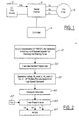
- V_offset is first plotted at zero speed.
- the V_offset is necessary to adjust the starting current to account for stator resistance and starting torque.
- w_rated_l is plotted at Vl (V_max), and a straight line is drawn between the two points, shown as 202 in Figure 4.
- w_rated_h is plotted at Vh (V_max), and a straight line is drawn between the two points, shown as 200 in Figure 4. This gives the profile that is used to determine how a PMSM motor will accelerate to its predetermined speed.
- the PMSM motor is driven from zero speed to a approximately 21,000 rpm, herein designated the turbo warm-up speed, where the industrial turbo engine coupled to the PMSM motor is warmed up for a maximum of 60 seconds.
- the industrial turbo engine is fired at approximately 8,000 rpm and remains coupled to the PMSM and the starter inverter.
- the PMSM motor is then accelerated from approximately 21,000 rpm to approximately 33,000 rpm, or around one-half of the rated speed for the industrial turbo engine.
- the starter inverter When approximately 33,000 rpm is reached, at the turbo uncoupling speed, the starter inverter will shut off and the industrial turbo engine will accelerate on its own to its desired speed, typically around the rated speed of the industrial turbo engine. At the point when the starter inverter is turned off and the turbo engine approaches its rated speed, the turbo engine drives the PMSM to generate electricity. When this happens, the PMSM is being used as a generator.
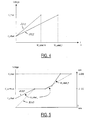
- Figure 5 represents the voltage profile as a function of time (shown as 400 on Figure 5) and the speed profile as a function of time (shown as 500 on Figure 5) for driving the PMSM motor from zero speed to the turbo uncoupling speed according to a preferred embodiment of the invention.
- the starter inverter drives the PMSM coupled to an industrial turbo motor from zero speed to the turbo warm-up speed along the low-speed V/f profile line described above in Figure 4.
- the turbo engine is fired at the turbo starting speed (not shown) at a point between zero speed and the turbo warm-up speed along the low-speed V/f profile.
- the PMSM motor is then held at the turbo warm-up speed at the corresponding voltage (designated V_warmup) until the industrial turbo engine warms up (for a maximum of 60 seconds).
- the PMSM motor is then accelerated along the low-speed V/f profile until it reaches a switching speed.
- the PMSM motor will then accelerate along the high-speed V/f profile described in Figure 4 until it reaches V_max, or the maximum AC voltage allowed for the system.
- the PMSM motor is then accelerated to the turbo uncoupling speed by increasing the frequency while the voltage is maintained at V_max.
- the industrial turbo engine will take over and continue accelerating to the rated speed or desired speed. Note that the switching speed is between V_warmup and V_max.
Abstract
Description
- The present invention relates to turbo engines, and more particularly to a method for controlling high-speed permanent magnet motors that are coupled to industrial turbo engines.
- Permanent magnet synchronous motors (PMSM) are widely used in motion controls, electric vehicles, and industrial turbo generators (ITG). PMSMs are typically coupled with engines to provide assistance to the engines at lower engine speeds. Because a turbo engine cannot start itself at zero speed, PMSMs using a starter inverter are needed to assist the turbo engine in accelerating to about half of its rated speed. At this speed, the turbo engine has sufficient torque to be driven to its rated speed without a PMSM.
- To start a turbo engine, and specifically an industrial turbo engine, a starter inverter drives the PMSM, which is coupled to the turbo engine, to an initial desired speed to warm up the turbo engine. The starter inverter, which converts direct current (DC) into alternating current (AC), takes power from either batteries or a rectified grid. After the turbo engine is warmed, the drive is then increased to a second desired speed, typically about half of the rated speed of the turbo engine. The turbo engine will then take over the process without the aid of the AC motor and continue accelerating to nominal speed.
- An "open-loop" volts per hertz control method is a commonly used AC motor control method. The volts per hertz (V/f) algorithm is used to run the motor at variable speeds. The V/f algorithm is very simple and inexpensive to implement in comparison to more sophisticated AC motor control algorithms. The "open-loop" control method varies the three-phase output frequency by adjusting the slope, or the ratio between frequency and voltage. Normally, a single straight-line V/f ratio is determined that drives the AC motor to the turbo uncoupling speed, where the turbo engine can produce sufficient torque to accelerate on its own to a desired speed without the aid of an AC motor. No sensing equipment is needed, the calculations are simpler and a less powerful, less expensive motor control unit (MCU) can be used.
- One problem with the "open-loop" control method is that due to a possible wide range of DC bus voltages and the short accelerating time, typically about 12 seconds, for an industrial turbo engine to accelerate from 0-33,000 rpm, a single straight-line voltage per hertz ratio calculated by the "open-loop" method does not give a satisfactory dynamic response. In addition, the "open loop" control method often results in larger line current outputs at high speeds, or unacceptable steady state current at low speeds if a short accelerating time is required.
- According to the present invention there is provided a method for driving a rotary machine coupled to a turbo engine at a predetermined DC bus voltage, the method comprising the steps of: controlling the speed of the rotary machine as a function of a voltage-offset value, an actual low-speed rated speed value, and an actual high-speed rated speed value.
- In a method and apparatus embodying the present invention, a permanent magnet synchronous motor (PMSM) is coupled to an industrial turbo engine. A battery or other DC power supply sends a DC voltage to a starter inverter, which modulates the DC bus voltage to a three-phase AC voltage, and sends it to the PMSM. The PMSM controller has a V/f algorithm that determines a V/f profile for the given DC bus voltage to drive the PMSM to a speed at which the industrial turbo engine has sufficient torque to accelerate without the aid of the PMSM motor, typically about one-half of the rated speed of the industrial turbo engine. The algorithm creates a V/f profile along a pathway where steady state and transient current are minimised. The V/f profile created from the V/f algorithm is a function of a calculated voltage-offset value, an actual low-speed rated speed value, and an actual high-speed rated speed value. The algorithm takes into account the wide range of potential DC bus voltages from the battery, which may have different charge levels at different times.
- A method and apparatus embodying the present invention provides a volts per hertz (V/f) profile from zero speed to very high-speeds. The V/f profile factors in the wide range of DC bus values and minimises the line to line current to a permanent magnet generator (PMG) motor.
- The present invention will now be described further, by way of example, with reference to the accompanying drawings, in which:
- Figure 1 is a simplified system diagram for a motor drive system;
- Figure 2 is a logic flow diagram for the method according to a preferred embodiment;
- Figure 3 is a V/f profile subroutine of
Step 30 of Figure 1 for determining the voltage-offset value and the actual speed value for low-speed and high-speed operations that minimise steady state and transient current; - Figure 4 is a V/f profile as determined in
Step 160 of Figure 3; and - Figure 5 is a plot of the voltage change as a function of time for driving the PMSM motor from zero speed to the turbo uncoupling speed and is a plot of the speed change as a function of time for driving the PMSM motor from zero speed to the turbo uncoupling speed.
-
- Figure 1 is a simplified system diagram for a motor drive system. The input to a
starter inverter 4 is a DC power supply 2 (or battery) with a bus voltage level (Vdc). The output of theinverter 4 is a three-phase AC voltage signal (Va, Vb, Vc) to drive a super high-speed permanent magnet (PM)motor 8. A controller 6, preferably microprocessor-based, directs thestarter inverter 4 to drive thePM motor 8 from zero speed to a desired speed in such a way as to minimise transient and steady state current. The controller 6 drives themotor 8 along a V/f profile that is a function of a voltage-offset value, a low-speed rated speed value, and a high-speed rated speed value. The voltage-offset value, the low-speed rated speed value, and the high-speed rated speed value are determined by the controller 6 for a particular DC bus voltage based upon the individual characteristics of themotor 8 and theDC power supply 2. - Figure 2 is a logic flow diagram for the method according to a preferred embodiment. In
Step 10, the characteristics of the PMSM/turbo coupled engine are determined, including the number of poles (p) in the stator. Desired speeds required for the operation are also determined, such as the turbo starting speed (the speed at which the turbo engine is fired, typically around 8,000 rpm), the turbo engine warm-up speed and the turbo uncoupling speed. The desired frequencies (w or f) are then calculated inStep 20 based on this desired speeds indicated inStep 10 from the formula [f=(RPM)(p)/120]. - In
Step 30, a voltage-offset value is calculated, and a V/f profile is determined at low and high-speed operations from this voltage-offset value and from low and high-speed rated speed values. This V/f profile incorporates every possible DC bus voltage value. A more detailed description ofStep 30 is detailed below in Figure 3. - In
Step 40, sinewaves for three-phases (a, b and c) are generated for the V/f profile and are sent to a three-phase inverter inStep 50. The three-phase inverter inStep 50 takes direct current (DC) from either a battery or a rectified power grid (Step 45) and modulates the DC current into an AC current having three-phases, designated Phase A, Phase B and Phase C. The three-phase current is fed into a stator winding of the PM motor inStep 60, which creates the motor action to accelerate the coupled turbo engine (not shown) to a desired speed. - Figure 3 shows the V/f profile subroutine for determining the voltage-offset value and the V/f profile of
Step 30 in Figure 2 for all of the possible DC bus voltages. The V/f profile (algorithm) controls both the frequency and the AC voltage in a proportional fashion up to the nominal operating frequency (or rated frequency (w rated)). Beyond this frequency, the AC voltage is held at its maximum value (V_max) while only the frequency is changed. The low boost voltage (v_offset) at zero speed is mainly dependent on the motor's IR drop and a required starting torque. - First, in
Step 100, the low DC voltage level (Vl) and high DC voltage level (Vh) are determined by known methods for the batteries that supply DC current to the starter inverter. In a preferred embodiment of the present invention, Vl is 300 volts and Vh is 450 volts. - Next, in
Step 110, a voltage-offset value for low DC voltage (Vosl) corresponding to Vl and a high DC voltage-offset (Vosh) are determined by known experimental methods. - Then, in
Step 130, an auto calculated voltage-offset value (V_offset), that is a function of DC bus voltage set in Step 120, is determined as: - Next in
Step 140, optimal rated speed values for low DC bus voltages at low-speed operations (w_rated_1_1) and high-speed operations (w_rated_1_h) are determined by known methods. Also, optimal rated speed values for high DC bus voltages at low-speed operations (w_rated_h_1) and high-speed operations (w_rated_h_h) are determined by known methods. - To determine the V/f profile boundaries for low-speed and high-speed operations, an actual rated speed value for low-speed (w_rated_1) operations and high-speed (w_rated_h) operations must be calculated in
Step 150. The calculations for determining w_rated_l and w_rated_h are: - Next, a V/f profile that incorporates the V_offset value and the two rated speed values calculated above is profiled in
Step 160. A plot of V_offset and the two rated speed values ofStep 160 are shown in Figure 4. Note that the voltage plotted on the y-axis is in terms of AC voltage. To create the profile, V_offset is first plotted at zero speed. The V_offset is necessary to adjust the starting current to account for stator resistance and starting torque. Second, w_rated_l, is plotted at Vl (V_max), and a straight line is drawn between the two points, shown as 202 in Figure 4. Third, w_rated_h is plotted at Vh (V_max), and a straight line is drawn between the two points, shown as 200 in Figure 4. This gives the profile that is used to determine how a PMSM motor will accelerate to its predetermined speed. - In operation, for an industrial turbo engine that is contemplated by the present invention, for any given DC bus voltage, the PMSM motor is driven from zero speed to a approximately 21,000 rpm, herein designated the turbo warm-up speed, where the industrial turbo engine coupled to the PMSM motor is warmed up for a maximum of 60 seconds. The industrial turbo engine is fired at approximately 8,000 rpm and remains coupled to the PMSM and the starter inverter. The PMSM motor is then accelerated from approximately 21,000 rpm to approximately 33,000 rpm, or around one-half of the rated speed for the industrial turbo engine. When approximately 33,000 rpm is reached, at the turbo uncoupling speed, the starter inverter will shut off and the industrial turbo engine will accelerate on its own to its desired speed, typically around the rated speed of the industrial turbo engine. At the point when the starter inverter is turned off and the turbo engine approaches its rated speed, the turbo engine drives the PMSM to generate electricity. When this happens, the PMSM is being used as a generator.
- Figure 5 represents the voltage profile as a function of time (shown as 400 on Figure 5) and the speed profile as a function of time (shown as 500 on Figure 5) for driving the PMSM motor from zero speed to the turbo uncoupling speed according to a preferred embodiment of the invention.
- In Figure 5, for any given DC bus voltage, the starter inverter drives the PMSM coupled to an industrial turbo motor from zero speed to the turbo warm-up speed along the low-speed V/f profile line described above in Figure 4. The turbo engine is fired at the turbo starting speed (not shown) at a point between zero speed and the turbo warm-up speed along the low-speed V/f profile. The PMSM motor is then held at the turbo warm-up speed at the corresponding voltage (designated V_warmup) until the industrial turbo engine warms up (for a maximum of 60 seconds). The PMSM motor is then accelerated along the low-speed V/f profile until it reaches a switching speed. The PMSM motor will then accelerate along the high-speed V/f profile described in Figure 4 until it reaches V_max, or the maximum AC voltage allowed for the system. The PMSM motor is then accelerated to the turbo uncoupling speed by increasing the frequency while the voltage is maintained at V_max. The industrial turbo engine will take over and continue accelerating to the rated speed or desired speed. Note that the switching speed is between V_warmup and V_max.
Claims (15)
- A method for driving a rotary machine coupled to a turbo engine at a predetermined DC bus voltage, the method comprising the steps of:
controlling the speed of the rotary machine as a function of a voltage-offset value, an actual low-speed rated speed value, and an actual high-speed rated speed value. - A method as claimed in claim 1, wherein further comprising the step of determining a voltage-offset value as a function of a minimum voltage-offset value, a maximum voltage-offset value, a minimum DC bus voltage, a maximum DC bus voltage, and the DC bus voltage for the rotary machine.
- A method as claimed in claim 1 or 2, wherein further comprising the step of determining an actual low-speed rated speed value as a function of an optimal low-speed low DC voltage rated speed value, an optimal low-speed high DC voltage rated speed value, a minimum DC bus voltage, a maximum DC bus voltage, and the DC bus voltage for the rotary machine.
- A method as claimed in any one of claims 1 to 3, wherein further comprising the step of determining an actual high-speed rated speed value as a function of an optimal high-speed low DC voltage rated speed value, an optimal high-speed high DC voltage rated speed value, a minimum DC bus voltage, a maximum DC bus voltage, and the DC bus voltage of the rotary machine.
- A method for starting a turbo engine coupled to a rotary machine for a given DC bus voltage, said method comprising the steps of:accelerating the rotary machine to a turbo warm-up speed along a low-speed V/f profile;starting the turbo engine at a turbo starting speed, where said turbo starting speed is less than said turbo warm-up speed;maintaining the rotary machine at said turbo warm-up speed for a predetermined time to warm-up the turbo engine;thereafter, accelerating the rotary machine from said turbo-warm-up speed to a switching speed along said low-speed V/f profile having a first slope;thereafter, accelerating the rotary machine from said switching speed to a second speed along a high-speed V/f profile having a second slope;thereafter, accelerating the rotary machine from said second speed to a turbo uncoupling speed; anduncoupling the rotary machine from the turbo engine; andaccelerating the turbo engine from said turbo uncoupling speed to a desired speed.
- A method as claimed in claim 5, wherein said low-speed V/f profile is a function of a voltage-offset value and an actual low-speed rated speed value.
- A method as claimed in claim 6, further comprising determining said voltage-offset value as a function of a minimum DC bus voltage, a maximum DC bus voltage, a minimum voltage-offset value, a maximum voltage-offset value and said DC bus voltage.
- A method as claimed in claim 6, further comprising determining said actual low-speed rated speed value as a function of an optimal low-speed low DC voltage rated speed value, an optimal low-speed high DC voltage rated speed value, a minimum DC bus voltage, a maximum DC bus voltage, and the given DC bus voltage.
- A method as claimed in claim 5, wherein said switching speed is greater than said turbo warm-up speed and less than said second speed.
- A method as claimed in claim 5, wherein said second speed is greater than said switching speed and less than said turbo uncoupling speed.
- A method as claimed in claim 5, wherein said high-speed V/f profile is a function of a voltage-offset value and an actual high-speed rated speed value.
- A method as claimed in claim 11, further comprising determining said voltage-offset value as a function of a minimum DC bus voltage, a maximum DC bus voltage, a minimum voltage-offset value, a maximum voltage-offset value and said DC bus voltage.
- A method as claimed in claim 11, further comprising determining said actual high-speed rated speed value as a function of an optimal high-speed low DC voltage rated speed value, an optimal high-speed high DC voltage rated speed value, a minimum DC bus voltage, a maximum DC bus voltage, and the given DC bus voltage.
- A method as claimed in claim 5, further comprising accelerating the rotary machine from said second speed to said turbo uncoupling speed at a constant AC voltage value, where said AC voltage value is a maximum allowable voltage corresponding to the given DC bus voltage.
- An apparatus for driving a turbo engine/rotary machine system at a given DC bus voltage from zero speed to a turbo uncoupling speed, said apparatus comprising:a turbo engine;a rotary machine (8) coupled to said turbo engine;a starter inverter (4) coupled to said rotary machine (8) for modulating the given DC bus voltage to form a three-phase AC voltage signal, said three-phase AC voltage signal driving said rotary machine; anda controller (6) coupled to said starter inverter for controlling the rotary machine to the turbo uncoupling speed along a V/f profile, said V/f profile being a function of a voltage-offset value, an actual low-speed rated speed value, and an actual high-speed rated speed value, a turbo warm-up speed, a switching speed, a second speed and the turbo uncoupling speed.
Applications Claiming Priority (2)
| Application Number | Priority Date | Filing Date | Title |
|---|---|---|---|
| US09/495,443 US6307275B1 (en) | 2000-01-31 | 2000-01-31 | Method and apparatus for controlling a high-speed AC permanent magnet synchronous motor coupled to an industrial turbo engine |
| US495443 | 2000-01-31 |
Publications (2)
| Publication Number | Publication Date |
|---|---|
| EP1122879A2 true EP1122879A2 (en) | 2001-08-08 |
| EP1122879A3 EP1122879A3 (en) | 2003-06-04 |
Family
ID=23968664
Family Applications (1)
| Application Number | Title | Priority Date | Filing Date |
|---|---|---|---|
| EP01300774A Withdrawn EP1122879A3 (en) | 2000-01-31 | 2001-01-29 | Method and apparatus for controlling rotary machine coupled to a turbo engine |
Country Status (3)
| Country | Link |
|---|---|
| US (3) | US6307275B1 (en) |
| EP (1) | EP1122879A3 (en) |
| JP (1) | JP4609971B2 (en) |
Cited By (1)
| Publication number | Priority date | Publication date | Assignee | Title |
|---|---|---|---|---|
| WO2006060319A1 (en) * | 2004-11-30 | 2006-06-08 | Honeywell International Inc. | High power density/limited dc ink voltage synchronous motor drive |
Families Citing this family (6)
| Publication number | Priority date | Publication date | Assignee | Title |
|---|---|---|---|---|
| US6307275B1 (en) * | 2000-01-31 | 2001-10-23 | Ford Global Technologies, Inc. | Method and apparatus for controlling a high-speed AC permanent magnet synchronous motor coupled to an industrial turbo engine |
| US7468595B2 (en) * | 2005-07-26 | 2008-12-23 | Eaton Corporation | System and method of controlling the start-up of an adjustable speed motor drive based sinusoidal output power conditioner |
| TWI439041B (en) | 2011-12-19 | 2014-05-21 | Ind Tech Res Inst | Method and apparatus for driving permanent magnet synchronous motor |
| WO2013094432A1 (en) * | 2011-12-22 | 2013-06-27 | 川崎重工業株式会社 | Gas turbine engine provided with heat exchanger, and method for starting gas turbine engine |
| JPWO2013094433A1 (en) * | 2011-12-22 | 2015-04-27 | 川崎重工業株式会社 | Gas turbine engine and starting method thereof |
| CN108443021A (en) * | 2018-03-16 | 2018-08-24 | 哈尔滨工业大学 | A kind of starter of gas turbine generator system |
Citations (4)
| Publication number | Priority date | Publication date | Assignee | Title |
|---|---|---|---|---|
| EP0357183A1 (en) * | 1988-08-01 | 1990-03-07 | General Motors Corporation | Automotive electrical apparatus having a starter/generator induction machine |
| US4949021A (en) * | 1988-11-14 | 1990-08-14 | Sunstrand Corporation | Variable speed constant frequency start system with selectable input power limiting |
| US5428275A (en) * | 1993-05-12 | 1995-06-27 | Sundstrand Corporation | Controlled starting method for a gas turbine engine |
| US5512811A (en) * | 1994-01-21 | 1996-04-30 | Sundstrand Corporation | Starter/generator system having multivoltage generation capability |
Family Cites Families (21)
| Publication number | Priority date | Publication date | Assignee | Title |
|---|---|---|---|---|
| DE2110747B2 (en) | 1971-03-06 | 1975-06-26 | Siemens Ag, 1000 Berlin Und 8000 Muenchen | Starting device for a generator coupled to a turbine |
| US3840799A (en) | 1973-09-11 | 1974-10-08 | Westinghouse Electric Corp | Commutatorless dc motor drive arrangement |
| DE2811123C2 (en) | 1978-03-15 | 1983-09-29 | Barmag Barmer Maschinenfabrik Ag, 5630 Remscheid | Procedure for starting up and ramping up a synchronous motor to operating speed with the aid of a converter |
| US4456830A (en) | 1982-04-22 | 1984-06-26 | Lockheed Corporation | AC Motor-starting for aircraft engines using APU free turbine driven generators |
| US4565957A (en) | 1983-06-30 | 1986-01-21 | Borg-Warner Corporation | Method and system for starting a motor-commutated SCR inverter |
| JPS62123985A (en) * | 1985-11-20 | 1987-06-05 | Mitsubishi Electric Corp | Controller for inverter |
| US4786852A (en) * | 1986-07-18 | 1988-11-22 | Sundstrand Corporation | Inverter operated turbine engine starting system |
| EP0267583B1 (en) | 1986-11-14 | 1992-11-11 | Kabushiki Kaisha Toshiba | Turbine helper drive apparatus |
| US4746850A (en) | 1987-02-12 | 1988-05-24 | Westinghouse Electric Corp. | Start-up system for a synchronous motor drive |
| US4908565A (en) * | 1987-02-18 | 1990-03-13 | Sundstrand Corporation | Power generating system |
| US4772802A (en) * | 1987-08-19 | 1988-09-20 | Sundstrand Corporation | Starting/generating system |
| US5055700A (en) * | 1989-10-16 | 1991-10-08 | Dhyanchand P John | Brushless generator having prime mover start capability |
| US5144564A (en) | 1991-01-08 | 1992-09-01 | University Of Tennessee Research Corp. | Rotor position estimation of a permanent magnet synchronous-machine for high performance drive |
| US5594322A (en) | 1993-05-12 | 1997-01-14 | Sundstrand Corporation | Starter/generator system with variable-frequency exciter control |
| US5430362A (en) * | 1993-05-12 | 1995-07-04 | Sundstrand Corporation | Engine starting system utilizing multiple controlled acceleration rates |
| US5493200A (en) | 1993-05-12 | 1996-02-20 | Sundstrand Corporation | Control for a brushless generator |
| US5581168A (en) | 1993-05-12 | 1996-12-03 | Sundstrand Corporation | Starter/generator system with DC link current control |
| US5363032A (en) * | 1993-05-12 | 1994-11-08 | Sundstrand Corporation | Sensorless start of synchronous machine |
| JPH1023756A (en) * | 1996-06-28 | 1998-01-23 | Mitsubishi Electric Corp | Voltage inverter device and method for controlling it |
| US6037752A (en) * | 1997-06-30 | 2000-03-14 | Hamilton Sundstrand Corporation | Fault tolerant starting/generating system |
| US6307275B1 (en) * | 2000-01-31 | 2001-10-23 | Ford Global Technologies, Inc. | Method and apparatus for controlling a high-speed AC permanent magnet synchronous motor coupled to an industrial turbo engine |
-
2000
- 2000-01-31 US US09/495,443 patent/US6307275B1/en not_active Expired - Lifetime
-
2001
- 2001-01-26 JP JP2001018377A patent/JP4609971B2/en not_active Expired - Fee Related
- 2001-01-29 EP EP01300774A patent/EP1122879A3/en not_active Withdrawn
- 2001-07-06 US US09/900,765 patent/US6492789B2/en not_active Expired - Lifetime
- 2001-07-06 US US09/900,774 patent/US6501244B2/en not_active Expired - Fee Related
Patent Citations (4)
| Publication number | Priority date | Publication date | Assignee | Title |
|---|---|---|---|---|
| EP0357183A1 (en) * | 1988-08-01 | 1990-03-07 | General Motors Corporation | Automotive electrical apparatus having a starter/generator induction machine |
| US4949021A (en) * | 1988-11-14 | 1990-08-14 | Sunstrand Corporation | Variable speed constant frequency start system with selectable input power limiting |
| US5428275A (en) * | 1993-05-12 | 1995-06-27 | Sundstrand Corporation | Controlled starting method for a gas turbine engine |
| US5512811A (en) * | 1994-01-21 | 1996-04-30 | Sundstrand Corporation | Starter/generator system having multivoltage generation capability |
Cited By (1)
| Publication number | Priority date | Publication date | Assignee | Title |
|---|---|---|---|---|
| WO2006060319A1 (en) * | 2004-11-30 | 2006-06-08 | Honeywell International Inc. | High power density/limited dc ink voltage synchronous motor drive |
Also Published As
| Publication number | Publication date |
|---|---|
| EP1122879A3 (en) | 2003-06-04 |
| US6501244B2 (en) | 2002-12-31 |
| US20020047681A1 (en) | 2002-04-25 |
| JP4609971B2 (en) | 2011-01-12 |
| JP2001238489A (en) | 2001-08-31 |
| US20020047682A1 (en) | 2002-04-25 |
| US6307275B1 (en) | 2001-10-23 |
| US6492789B2 (en) | 2002-12-10 |
Similar Documents
| Publication | Publication Date | Title |
|---|---|---|
| US5029263A (en) | Electric start control of a VSCF system | |
| US7227271B2 (en) | Method and apparatus for controlling an engine start system | |
| US4949021A (en) | Variable speed constant frequency start system with selectable input power limiting | |
| US5055764A (en) | Low voltage aircraft engine starting system | |
| US5036267A (en) | Aircraft turbine start from a low voltage battery | |
| US6528967B2 (en) | Permanent magnet brushless electric motor system and method of using same | |
| EP1553275B1 (en) | A method and apparatus for starting a gas turbine using a polyphase electric power generator | |
| US5428275A (en) | Controlled starting method for a gas turbine engine | |
| US7116073B1 (en) | Methods and apparatus for controlling a motor/generator | |
| US7135784B2 (en) | Fast torque control of a belted alternator starter | |
| JP2002507377A (en) | Electrical system for turbine / alternator on common shaft | |
| US5587641A (en) | VSCF start system with precise voltage control | |
| US7135829B1 (en) | Methods and apparatus for controlling a motor/generator | |
| JPH08322298A (en) | Wind power generating apparatus | |
| US6307275B1 (en) | Method and apparatus for controlling a high-speed AC permanent magnet synchronous motor coupled to an industrial turbo engine | |
| EP1753123B1 (en) | Methods and apparatus for controlling a motor/generator | |
| JP3788925B2 (en) | Wind power generator using permanent magnet type synchronous generator and its starting method | |
| US8878498B2 (en) | Method for reducing a voltage ripple due to rotational nonuniformity of a generator driven by an internal combustion engine | |
| US6703808B1 (en) | Active power limiting for starter/alternator in the generation mode | |
| RU2745149C1 (en) | Method of controlling a diesel generator set when an asynchronous motor is turned on | |
| RU2173020C2 (en) | Power system with induction starter-generator | |
| JP4180983B2 (en) | Control device for rotating electrical machine for vehicle | |
| JP2004218467A (en) | Engine drive power generating device | |
| JPH09215102A (en) | Equipment and method for controlling electric car | |
| JP4021192B2 (en) | Control method and apparatus for variable speed generator and variable speed pumped storage power generation system |
Legal Events
| Date | Code | Title | Description |
|---|---|---|---|
| PUAI | Public reference made under article 153(3) epc to a published international application that has entered the european phase |
Free format text: ORIGINAL CODE: 0009012 |
|
| AK | Designated contracting states |
Kind code of ref document: A2 Designated state(s): AT BE CH CY DE DK ES FI FR GB GR IE IT LI LU MC NL PT SE TR |
|
| AX | Request for extension of the european patent |
Free format text: AL;LT;LV;MK;RO;SI |
|
| PUAL | Search report despatched |
Free format text: ORIGINAL CODE: 0009013 |
|
| AK | Designated contracting states |
Designated state(s): AT BE CH CY DE DK ES FI FR GB GR IE IT LI LU MC NL PT SE TR |
|
| AX | Request for extension of the european patent |
Extension state: AL LT LV MK RO SI |
|
| RIC1 | Information provided on ipc code assigned before grant |
Ipc: 7F 02N 11/08 B Ipc: 7H 02P 9/44 B Ipc: 7H 02P 9/08 A |
|
| AKX | Designation fees paid |
Designated state(s): DE FR GB |
|
| STAA | Information on the status of an ep patent application or granted ep patent |
Free format text: STATUS: THE APPLICATION IS DEEMED TO BE WITHDRAWN |
|
| 18D | Application deemed to be withdrawn |
Effective date: 20031205 |