EP0356022B1 - Filterpatronenbefestigung für einen Staubsammler - Google Patents
Filterpatronenbefestigung für einen Staubsammler Download PDFInfo
- Publication number
- EP0356022B1 EP0356022B1 EP89307698A EP89307698A EP0356022B1 EP 0356022 B1 EP0356022 B1 EP 0356022B1 EP 89307698 A EP89307698 A EP 89307698A EP 89307698 A EP89307698 A EP 89307698A EP 0356022 B1 EP0356022 B1 EP 0356022B1
- Authority
- EP
- European Patent Office
- Prior art keywords
- cartridge filter
- cartridge
- walls
- powder collector
- opening
- Prior art date
- Legal status (The legal status is an assumption and is not a legal conclusion. Google has not performed a legal analysis and makes no representation as to the accuracy of the status listed.)
- Expired - Lifetime
Links
Images

Classifications
-
- B—PERFORMING OPERATIONS; TRANSPORTING
- B01—PHYSICAL OR CHEMICAL PROCESSES OR APPARATUS IN GENERAL
- B01D—SEPARATION
- B01D46/00—Filters or filtering processes specially modified for separating dispersed particles from gases or vapours
- B01D46/0002—Casings; Housings; Frame constructions
- B01D46/0005—Mounting of filtering elements within casings, housings or frames
-
- B—PERFORMING OPERATIONS; TRANSPORTING
- B01—PHYSICAL OR CHEMICAL PROCESSES OR APPARATUS IN GENERAL
- B01D—SEPARATION
- B01D46/00—Filters or filtering processes specially modified for separating dispersed particles from gases or vapours
- B01D46/24—Particle separators, e.g. dust precipitators, using rigid hollow filter bodies
- B01D46/2403—Particle separators, e.g. dust precipitators, using rigid hollow filter bodies characterised by the physical shape or structure of the filtering element
- B01D46/2411—Filter cartridges
-
- B—PERFORMING OPERATIONS; TRANSPORTING
- B01—PHYSICAL OR CHEMICAL PROCESSES OR APPARATUS IN GENERAL
- B01D—SEPARATION
- B01D46/00—Filters or filtering processes specially modified for separating dispersed particles from gases or vapours
- B01D46/42—Auxiliary equipment or operation thereof
- B01D46/48—Removing dust other than cleaning filters, e.g. by using collecting trays
-
- B—PERFORMING OPERATIONS; TRANSPORTING
- B01—PHYSICAL OR CHEMICAL PROCESSES OR APPARATUS IN GENERAL
- B01D—SEPARATION
- B01D46/00—Filters or filtering processes specially modified for separating dispersed particles from gases or vapours
- B01D46/56—Filters or filtering processes specially modified for separating dispersed particles from gases or vapours with multiple filtering elements, characterised by their mutual disposition
- B01D46/58—Filters or filtering processes specially modified for separating dispersed particles from gases or vapours with multiple filtering elements, characterised by their mutual disposition connected in parallel
-
- B—PERFORMING OPERATIONS; TRANSPORTING
- B01—PHYSICAL OR CHEMICAL PROCESSES OR APPARATUS IN GENERAL
- B01D—SEPARATION
- B01D2265/00—Casings, housings or mounting for filters specially adapted for separating dispersed particles from gases or vapours
- B01D2265/02—Non-permanent measures for connecting different parts of the filter
- B01D2265/024—Mounting aids
- B01D2265/025—Mounting aids making use of ramps or cams
-
- B—PERFORMING OPERATIONS; TRANSPORTING
- B01—PHYSICAL OR CHEMICAL PROCESSES OR APPARATUS IN GENERAL
- B01D—SEPARATION
- B01D2271/00—Sealings for filters specially adapted for separating dispersed particles from gases or vapours
- B01D2271/02—Gaskets, sealings
- B01D2271/022—Axial sealings
Definitions
- This invention relates to a powder collector for a powder booth, and more particularly, the invention is directed to the sealed mounting of cartridges in the collector.
- the powder booth is well known, and one form of it is described in US-A-4 723 505.
- the powder booth has a chamber through which an object to be finished with powder is conveyed.
- Electrostatic guns fire powder into the atmosphere surrounding the object to be finished, and much of the powder adheres to that object.
- the remainder of the powder is conveyed by airflow and gravity through the powder booth to a collector.
- Collectors generally have a filter medium through which the air from the powder booth is drawn, the powder being arrested by the medium. Reverse pulses are from time to time introduced into the reverse side of the medium to knock the powder off the medium, thereby preventing its being clogged.
- the thus filtered air is then directed through a final filter and into the plant atmosphere.
- the final filter is provided to assure the cleanliness of the air that is introduced into the plant.
- the powder collector In the powder booth of US-A-4 723 505, the powder collector consists of a housing that is mounted on castered wheels so that it can be rolled into and out of position adjacent the powder booth, thereby permitting the quick changeover from one colour powder to another.
- the housing has opposed walls with opposed openings in the walls. Extending across the housing is a triangular tower structure formed of three triangularly-spaced rods, the rods being cantilevered from one end of the housing adjacent the air outlet opening.
- the free end of the tower has a plate and a bolt projecting from the plate, the plate and bolt being located adjacent the opposite opening.
- a hollow cylindrical cartridge is mounted in the collector adjacent each opening by sliding it over the tower structure.
- a plate is bolted onto the projecting nut with the bolt tightening the plate against the cartridge and against the wall of the housing.
- Gaskets are provided at the ends of the cartridge, and a gasket between the plate and the housing wall is provided in order to seal the cartridge within the collector.
- the structure described normally provides a satisfactory seal. However, when a collector is transported from the factory to the finisher, tightened bolts become loosened and leakage can occur. Further, if the housing, which is formed of sheet metal, is manufactured slightly out of true so that the opposed walls are not precisely parallel to one another, the clamping of gaskets is not uniform and leakage can occur.
- a powder collector in accordance with the invention comprises at least one hollow cartridge filter disposed between two opposing walls, each cartridge being open at one end and closed at the other end, one of the walls having an opening or openings, each opening being aligned with a cartridge filter so that the open end of each cartridge filter overlies an opening, and a gasket surrounding each opening to form a seal between the wall and each cartridge filter characterised in that at least one pair of parallel rods underlying each cartridge filter extends between the two walls, each pair of rods providing a support for a cartridge filter, and in that means engageable with the closed end of the cartridge filter are provided for compressing the gasket between the wall and the open end of the cartridge filter.
- the two spaced parallel rods are welded between the opposed walls, the two rods providing a support or saddle onto which the cartridge is placed.
- a third rod is bolted across the top of the cartridge so that the cartridge is surrounded by a preferably equiangular configuration of rods secured to the opposed walls.
- the compressing means is a bolt which is threaded into the closed wall and is engageable with the closed end of a cartridge.
- the bolt is tightened to drive its inner end inwardly against the cartridge, the opposite end of the cartridge, carrying a gasket, is forced against the opposed wall around the discharge opening therein.
- a plate may be mounted on the inner end of the bolt to engage the closed end of the cartridge.
- the present invention facilitates installation, increases structural integrity, reduces the cost of the collector, and in simplifying the collector improves it aesthetically.
- the compressing means may comprise a rod which is slidable in the second wall and a spring to urge the rod against the closed end of this cartridge.
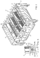
- a powder collector is shown generally at 10 and includes a housing 11 with side walls 15 and 16.
- Side wall 15 has discharge openings 17 and the opposed wall 16 is closed.
- Cartridges 20 are mounted in the collector between the walls 15 and 16 and are preferably formed in two sections.
- Section 21 has a closed end cap 22 and an open end 23.
- the adjacent cartridge section has two open ends 26.
- a circular gasket is placed between the two sections 21 and 25, and a gasket is placed between the open end 26 and the wall 15 so as to seal the cartridge around the opening 17.
- the housing 11 has an open top 28 that may be clamped snugly against an opening in a spray chamber where product is sprayed with powder. Air laden with excess powder flows through the open top 28 of the collector and against the cartridges. The cartridges arrest the flow of powder while the thus cleaned air passes through the openings 17 and onto a final filter, not shown. See US-A-4 723 505, the disclosure for which is specifically incorporated herein for reference, for a description of the complete powder booth.
- a pair of spaced parallel rods 30 extend between the two walls 15 and 16 to form a saddle or support for the cartridge.
- the rods 30 are preferably welded permanently into place between the two walls 15 and 16.
- a third rod 31 has a head on one end and is threaded on the other end so that it can be removably mounted across the span between the two walls 15 and 16.
- the rods surround the opening 17 so that when the cartridge is in position surrounded by the rods, the open end of each cartridge is aligned with a respective opening 17.
- the cartridge 20 is an elongated hollow member made principally of filter material 37. As shown in Fig. 4, the open end of the cartridge is provided with a ring-shaped cap 35, presenting an opening 36 through which air can flow. The opposite end of the cartridge has a closed end cap 22, the end cap 22 having a central recess 41 of about 8" (20 cm) in diameter. A ring-shaped gasket of rectangular cross-section is adhesively-secured to the open end cap 35. The gasket is about 1" (2.5 cm) across and 1 ⁇ 2" (1.3 cm) thick and has an exposed sawtooth surface 43 to provide sealing points. The gasket may be made of silicone rubber of about 80 durometer. Identical gaskets are provided between the cartridge sections 21 and 25 and the cartridge 25 and the housing wall 15.
- a torque nut 50 is welded to the wall 16 around an opening 51 in the wall.
- a threaded rod 55 is threaded into the torque nut 50 and has a head 56 provided at one end for rotating the rod in order to clamp the cartridges.
- the opposite end of the rod is rotatably mounted to a compression plate 60 which is slightly less than 8" (20 cm) in diameter so that it seats in the recess 41 of the end cap 22.
- the cartridges In operation, the cartridges, with closed end caps 22, are placed on the lower rods 30 with the closed end caps adjacent the wall 16.
- Cartridge sections 25 having open ends are placed on the rods 30 with the gasket end of the cartridge section being against the wall 15 so that the gasket surrounds the opening 17.
- the rods 31 are inserted and secured between the two walls 15 and 16.
- the cartridges are securely mounted in a rugged cage formed by the walls 15, 16 and the rods 30 and 31.
- Each threaded rod 55 is rotated inwardly, thereby positioning the compression plate 60 against the end cap 22 to compress the gaskets and to securely seal the cartridge sections against leakage from between the wall of the collector housing and the end of the cartridge.
- the compression sealing means may be a spring-loaded clamping plate instead of the threaded rod 55.
- the clamping plate 60 is mounted on a smooth rod 65.
- a compression spring is mounted between wall 16 and plate 60 to urge the plate against the cartridge.
- the rod carries a transverse pin 66 which can pass through a slot 67 in wall 16.
- To install a cartridge firstly the rod 65 is withdrawn by pulling on handle 68 until the pin 66 passes through slot 67. The handle is then twisted to misalign pin 66 with respect to slot 67, thereby holding the rod in its withdrawn position.
- the cartridge sections 21,25 are inserted and the rod is then returned to its original position.
- the spring pressure on the cartridge 20 is always uniform and does not depend on the degree to which a screw is tightened.
Landscapes
- Chemical & Material Sciences (AREA)
- Chemical Kinetics & Catalysis (AREA)
- Physics & Mathematics (AREA)
- Geometry (AREA)
- Filtering Of Dispersed Particles In Gases (AREA)
- Sampling And Sample Adjustment (AREA)
- Physical Vapour Deposition (AREA)
- Treatment Of Liquids With Adsorbents In General (AREA)
- Separating Particles In Gases By Inertia (AREA)
Claims (8)
- Pulversammler mit mindestens einer hohlen, zwischen zwei gegenüberliegenden Wänden angeordneten Filterpatrone, die an einem Ende offen und an dem anderen Ende geschlossen ist,
bei dem eine der Wände eine Öffnung oder Öffnungen aufweist, die jeweils mit einer Filterpatrone fluchtet/fluchten, so daß das offene Ende jeder Filterpatrone an einer Öffnung liegt,
und bei dem eine Dichtung jede Öffnung umgibt, um eine Abdichtung zwischen der Wand und jeder Filterpatrone zu bilden,
dadurch gekennzeichnet,
daß sich mindestens ein Paar paralleler Stäbe (30) zwischen den zwei Wänden (15, 16) erstreckt, jeweils einer Filterpatrone (20) zugeordnet ist und eine Abstützung für die Filterpatrone (20) bereitstellt, und daß mit dem geschlossenen Ende der Filterpatrone (20) in Eingriff bringbare Mittel (55, 60, 65) zum Zusammendrücken der Dichtung zwischen der Wand (15) und dem offenen Ende der Filterpatrone (20) vorgesehen sind. - Pulversammler nach Anspruch 1,
dadurch gekennzeichnet, daß sich mindestens ein dritter Stab (31) zwischen den Wänden (15, 16) erstreckt, um einen starren, jede Filterpatrone (20) umgebenden Käfig herzustellen, wobei jeder Stab (31) parallel zu einem Stab-Paar (30) und an einer Filterpatrone (20) angeordnet und lösbar an den Wänden (15, 16) befestigt ist. - Pulversammler nach Anspruch 1 oder 2,
dadurch gekennzeichnet, daß die Mittel zum Zusammendrücken eine Schraube (55) aufweisen, die in die zweite Wand (16) der zwei Wände geschraubt und mit dem geschlossenen Ende (22) der Filterpatrone in Eingriff ist. - Pulversammler nach Anspruch 3,
dadurch gekennzeichnet, daß eine Platte (60) drehbar an dem inneren Ende der Schraube (55) befestigt und mit dem geschlossenen Ende (22) der Filterpatrone in Eingriff ist, um die Filterpatrone (20) axial zu bewegen und die Dichtung zusammenzudrücken. - Pulversammler nach Anspruch 1 oder 2,
dadurch gekennzeichnet, daß die Mittel zum Zusammendrücken einen Stab (65) aufweisen, der in der zweiten Wand (16) der zwei Wände verschiebbar ist, und daß eine Druckfeder den Stab (65) gegen das geschlossene Ende (22) der Filterpatrone preßt. - Pulversammler nach einem der vorhergehenden Ansprüche,
dadurch gekennzeichnet, daß die Filterpatrone (20) aus zwei separaten, durchgehend hohlen Teilen (21, 25) gebildet ist und eine Dichtung zwischen den hohlen Teilen vorgesehen ist. - Pulversammler nach einem der vorhergehenden Ansprüche,
dadurch gekennzeichnet, daß die Filterpatrone (20) eine geschlossene Kappe (22) an einem Ende und eine offene Kappe (35) an dem anderen Ende aufweist. - Pulversammler nach einem der vorhergehenden Ansprüche,
dadurch gekennzeichnet, daß die Filterpatrone (20) ein längliches, hohles, im wesentlichen aus einem Filtermaterial (37) gebildetes Teil ist.
Priority Applications (1)
| Application Number | Priority Date | Filing Date | Title |
|---|---|---|---|
| AT89307698T ATE103199T1 (de) | 1988-08-08 | 1989-07-28 | Filterpatronenbefestigung fuer einen staubsammler. |
Applications Claiming Priority (2)
| Application Number | Priority Date | Filing Date | Title |
|---|---|---|---|
| US229431 | 1988-08-08 | ||
| US07/229,431 US4871380A (en) | 1988-08-08 | 1988-08-08 | Cartridge mount for powder collector |
Publications (2)
| Publication Number | Publication Date |
|---|---|
| EP0356022A1 EP0356022A1 (de) | 1990-02-28 |
| EP0356022B1 true EP0356022B1 (de) | 1994-03-23 |
Family
ID=22861226
Family Applications (1)
| Application Number | Title | Priority Date | Filing Date |
|---|---|---|---|
| EP89307698A Expired - Lifetime EP0356022B1 (de) | 1988-08-08 | 1989-07-28 | Filterpatronenbefestigung für einen Staubsammler |
Country Status (8)
| Country | Link |
|---|---|
| US (1) | US4871380A (de) |
| EP (1) | EP0356022B1 (de) |
| JP (1) | JP2810132B2 (de) |
| AT (1) | ATE103199T1 (de) |
| AU (1) | AU605091B2 (de) |
| CA (1) | CA1337475C (de) |
| DE (1) | DE68914063T2 (de) |
| ES (1) | ES2050807T3 (de) |
Families Citing this family (31)
| Publication number | Priority date | Publication date | Assignee | Title |
|---|---|---|---|---|
| US5078084A (en) * | 1990-04-16 | 1992-01-07 | Nordson Corporation | Powder coating system |
| US5306332A (en) * | 1991-05-14 | 1994-04-26 | Air-Gonomics, Inc. | Columnar filtering unit for spray painting |
| DE4207023C2 (de) * | 1992-03-06 | 1994-04-21 | Schlick Roto Jet Masch | Filtervorrichtung mit Gehäuse und in dem Gehäuse befindlichen Filterelementen |
| US5261934A (en) * | 1992-03-17 | 1993-11-16 | Nordson Corporation | Powder collection method and apparatus with isolated filter pulsing and compression mounted cartridges |
| US5223008A (en) * | 1992-08-24 | 1993-06-29 | Flex-Kleen Corp. | Horizontally mounted filter cartridge dust collector |
| US5290330A (en) * | 1993-06-10 | 1994-03-01 | The Johns Hopkins University | HEPA filtration system |
| FR2717706B1 (fr) * | 1994-03-23 | 1996-06-14 | Efficience Technologies Sarl | Cartouche pour un filtre prévu pour éliminer des particules présentes dans un flux d'air sous pression et un filtre destiné à recevoir une telle cartouche. |
| US5803941A (en) * | 1995-01-12 | 1998-09-08 | Donaldson Company, Inc. | Filter element |
| US6027540A (en) * | 1997-03-31 | 2000-02-22 | Destec Energy, Inc. | Apparatus for removal of particulate matter from gas streams |
| JPH10315897A (ja) * | 1997-05-15 | 1998-12-02 | Daicel Chem Ind Ltd | エアバッグ用ガス発生器のクーラント/フィルタ |
| US6676721B1 (en) * | 2000-06-02 | 2004-01-13 | Donaldson Company, Inc. | Multistage air cleaner including pulse cleaning system |
| US6419720B1 (en) | 2000-04-26 | 2002-07-16 | Nordson Corporation | Modular power coating booth |
| US6780247B2 (en) * | 2000-04-26 | 2004-08-24 | Nordson Corporation | Modular powder coating booth |
| MXPA05003691A (es) | 2002-10-07 | 2005-11-17 | James Hardie Int Finance Bv | Material mixto de fibrocemento de densidad media durable. |
| AU2005206522B2 (en) | 2004-01-12 | 2010-03-11 | James Hardie Technology Limited | Composite fiber cement article with radiation curable component |
| US7998571B2 (en) * | 2004-07-09 | 2011-08-16 | James Hardie Technology Limited | Composite cement article incorporating a powder coating and methods of making same |
| ATE531440T1 (de) * | 2005-03-31 | 2011-11-15 | Donaldson Co Inc | Luftreiniger-anordnung |
| WO2007105232A2 (en) * | 2006-03-13 | 2007-09-20 | Nordson India Private Limited | Cartridge in capsule |
| US7404839B2 (en) * | 2006-03-17 | 2008-07-29 | Tdc Filter Manufacturing, Inc. | Filter assembly and adaptor |
| US8993462B2 (en) | 2006-04-12 | 2015-03-31 | James Hardie Technology Limited | Surface sealed reinforced building element |
| US7785384B2 (en) * | 2007-01-09 | 2010-08-31 | Honeywell International Inc. | Pleated diesel particulate filter assembly |
| US8317890B2 (en) | 2008-08-29 | 2012-11-27 | Donaldson Company, Inc. | Filter assembly; components therefor; and, methods |
| ITMI20090582A1 (it) * | 2009-04-09 | 2010-10-10 | Saipem Spa | Filtro per fluidi, in particolare per gas in impianti petrolchimici |
| MX359078B (es) | 2012-01-05 | 2018-09-13 | Bha Altair Llc | Medio a prueba de agua y repelente de sal, y filtro. |
| USD698017S1 (en) | 2012-07-25 | 2014-01-21 | Tdc Filter Manufacturing, Inc. | Filter adaptor |
| US9605628B2 (en) * | 2014-03-06 | 2017-03-28 | Benjamin Lee Woodward | Non-invasive pneumatic filter cleaning apparatus and method |
| JP2016195962A (ja) * | 2015-04-02 | 2016-11-24 | 賢 飯田 | 集じん装置およびカートリッジフィルター |
| US10821391B2 (en) * | 2018-02-22 | 2020-11-03 | Lincoln Global, Inc. | Dust collector |
| US10940423B2 (en) * | 2018-04-19 | 2021-03-09 | Ingersoll-Rand Industrial U.S., Inc. | Compressor system and filter housing |
| IT202100021452A1 (it) * | 2021-08-06 | 2023-02-06 | Ufi Innovation Ct Srl | Assieme filtrazione aria |
| DE102024111993A1 (de) * | 2024-04-29 | 2025-10-30 | Mann+Hummel Gmbh | Rundfilterelement, insbesondere zur Gasfiltration |
Family Cites Families (16)
| Publication number | Priority date | Publication date | Assignee | Title |
|---|---|---|---|---|
| US2521060A (en) * | 1946-04-19 | 1950-09-05 | William W Hallinan | Fil ter |
| DE2638142A1 (de) * | 1976-05-06 | 1977-11-17 | Textron Inc | Filter |
| JPS5624507Y2 (de) * | 1976-12-15 | 1981-06-09 | ||
| US4277260A (en) * | 1979-08-14 | 1981-07-07 | Browning Jesse H | Powder collectors |
| US4298474A (en) * | 1979-12-14 | 1981-11-03 | Peerless Manufacturing Company | Multiple filter vessel |
| JPS5835732B2 (ja) * | 1979-12-26 | 1983-08-04 | 日本シユ−マツハ−株式会社 | 「ろ」過器装置 |
| US4504293A (en) * | 1980-11-06 | 1985-03-12 | Donaldson Company, Inc. | Self-cleaning air filter |
| US4395269B1 (en) * | 1981-09-30 | 1994-08-30 | Donaldson Co Inc | Compact dust filter assembly |
| US4545324A (en) * | 1984-05-09 | 1985-10-08 | Jess Browning | Powder spray booth and interchangeable collectors |
| DE3527766A1 (de) * | 1985-08-02 | 1987-02-12 | Intensiv Filter Gmbh | Einrichtung zum befestigen von filterpatronen in staubfiltern |
| US4723505A (en) * | 1986-03-17 | 1988-02-09 | Nordson Corporation | Powder booth |
| JPS6369521U (de) * | 1986-10-27 | 1988-05-10 | ||
| US4704953A (en) * | 1986-11-12 | 1987-11-10 | Nordson Corporation | Powder spray system |
| US4735638A (en) * | 1986-11-18 | 1988-04-05 | The United States Of America As Represented By The United States Department Of Energy | Filter unit for use at high temperatures |
| US4775398A (en) * | 1987-01-30 | 1988-10-04 | Howeth David Franklin | Structurally improved filter housing and mounting apparatus |
| US4758256A (en) * | 1987-06-25 | 1988-07-19 | Allied-Signal Inc. | Air filter with removable bridge assembly |
-
1988
- 1988-08-08 US US07/229,431 patent/US4871380A/en not_active Expired - Lifetime
-
1989
- 1989-06-21 CA CA000603544A patent/CA1337475C/en not_active Expired - Fee Related
- 1989-06-22 AU AU36773/89A patent/AU605091B2/en not_active Expired - Fee Related
- 1989-07-28 DE DE68914063T patent/DE68914063T2/de not_active Expired - Fee Related
- 1989-07-28 EP EP89307698A patent/EP0356022B1/de not_active Expired - Lifetime
- 1989-07-28 AT AT89307698T patent/ATE103199T1/de not_active IP Right Cessation
- 1989-07-28 ES ES89307698T patent/ES2050807T3/es not_active Expired - Lifetime
- 1989-08-08 JP JP1203993A patent/JP2810132B2/ja not_active Expired - Fee Related
Also Published As
| Publication number | Publication date |
|---|---|
| AU3677389A (en) | 1990-02-08 |
| ATE103199T1 (de) | 1994-04-15 |
| DE68914063D1 (de) | 1994-04-28 |
| DE68914063T2 (de) | 1994-08-11 |
| AU605091B2 (en) | 1991-01-03 |
| ES2050807T3 (es) | 1994-06-01 |
| JP2810132B2 (ja) | 1998-10-15 |
| EP0356022A1 (de) | 1990-02-28 |
| JPH0268107A (ja) | 1990-03-07 |
| CA1337475C (en) | 1995-10-31 |
| US4871380A (en) | 1989-10-03 |
Similar Documents
| Publication | Publication Date | Title |
|---|---|---|
| EP0356022B1 (de) | Filterpatronenbefestigung für einen Staubsammler | |
| US4357151A (en) | Electrostatically augmented cartridge type dust collector and method | |
| US3740934A (en) | Air filtering unit including a clamping assembly | |
| US5395509A (en) | Container for a refrigerant system filter | |
| US4159197A (en) | Suspension gasket seal and system for baghouse filter units | |
| WO1990000434A1 (en) | Filters | |
| US4882047A (en) | Zero-void column end plate for chromatography | |
| AU653695B2 (en) | Powder collection method and apparatus with isolated filter pulsing and compression mounted cartridges | |
| EP0034644B1 (de) | Druckgasanschluss bei Staubgasfiltern | |
| US9815013B2 (en) | Filter element support assembly, quick installation system, and methods | |
| JP2004506504A (ja) | フィルタ構造の装置および方法 | |
| CA2126739A1 (en) | Filter and a Method for Separating Charged Particles from a Liquid Stream | |
| GB2171923A (en) | Refillable filter-drier assembly | |
| EP0105948B1 (de) | Lösbare Klemmverbindung | |
| AU2001283200A1 (en) | A filter construction apparatus and method | |
| AU2001283200A2 (en) | A filter construction apparatus and method | |
| US5580454A (en) | Backwashing filter with increased filtration surface area | |
| US20020121469A1 (en) | Single cartridge filter housing | |
| US4759845A (en) | Plural filter apparatus with filtration gasket | |
| CA2199029A1 (en) | Device for coupling pipe sections | |
| US3954618A (en) | Filter tube holder and filter assembly | |
| EP0234229B1 (de) | Lufttrockner | |
| US3593502A (en) | Mounting for fluid filters | |
| DE69318019T2 (de) | Verbesserungen einer Pulverbeschichtungsvorrichtung | |
| CA2046379A1 (en) | Filtering device, especially for the separation of coarse particles from a lubricant suspension, and process for its use |
Legal Events
| Date | Code | Title | Description |
|---|---|---|---|
| PUAI | Public reference made under article 153(3) epc to a published international application that has entered the european phase |
Free format text: ORIGINAL CODE: 0009012 |
|
| AK | Designated contracting states |
Kind code of ref document: A1 Designated state(s): AT BE CH DE ES FR GB GR IT LI LU NL SE |
|
| 17P | Request for examination filed |
Effective date: 19900407 |
|
| 17Q | First examination report despatched |
Effective date: 19920527 |
|
| GRAA | (expected) grant |
Free format text: ORIGINAL CODE: 0009210 |
|
| AK | Designated contracting states |
Kind code of ref document: B1 Designated state(s): AT BE CH DE ES FR GB GR IT LI LU NL SE |
|
| PG25 | Lapsed in a contracting state [announced via postgrant information from national office to epo] |
Ref country code: SE Free format text: THE PATENT HAS BEEN ANNULLED BY A DECISION OF A NATIONAL AUTHORITY Effective date: 19940323 Ref country code: NL Effective date: 19940323 Ref country code: GR Free format text: LAPSE BECAUSE OF FAILURE TO SUBMIT A TRANSLATION OF THE DESCRIPTION OR TO PAY THE FEE WITHIN THE PRESCRIBED TIME-LIMIT Effective date: 19940323 Ref country code: BE Effective date: 19940323 Ref country code: AT Effective date: 19940323 |
|
| REF | Corresponds to: |
Ref document number: 103199 Country of ref document: AT Date of ref document: 19940415 Kind code of ref document: T |
|
| ET | Fr: translation filed | ||
| REF | Corresponds to: |
Ref document number: 68914063 Country of ref document: DE Date of ref document: 19940428 |
|
| ITF | It: translation for a ep patent filed | ||
| REG | Reference to a national code |
Ref country code: ES Ref legal event code: FG2A Ref document number: 2050807 Country of ref document: ES Kind code of ref document: T3 |
|
| PG25 | Lapsed in a contracting state [announced via postgrant information from national office to epo] |
Ref country code: LU Free format text: LAPSE BECAUSE OF NON-PAYMENT OF DUE FEES Effective date: 19940731 |
|
| NLV1 | Nl: lapsed or annulled due to failure to fulfill the requirements of art. 29p and 29m of the patents act | ||
| PLBE | No opposition filed within time limit |
Free format text: ORIGINAL CODE: 0009261 |
|
| STAA | Information on the status of an ep patent application or granted ep patent |
Free format text: STATUS: NO OPPOSITION FILED WITHIN TIME LIMIT |
|
| 26N | No opposition filed | ||
| PGFP | Annual fee paid to national office [announced via postgrant information from national office to epo] |
Ref country code: ES Payment date: 19990707 Year of fee payment: 11 |
|
| PG25 | Lapsed in a contracting state [announced via postgrant information from national office to epo] |
Ref country code: ES Free format text: LAPSE BECAUSE OF NON-PAYMENT OF DUE FEES Effective date: 20000729 |
|
| REG | Reference to a national code |
Ref country code: GB Ref legal event code: IF02 |
|
| PGFP | Annual fee paid to national office [announced via postgrant information from national office to epo] |
Ref country code: GB Payment date: 20030630 Year of fee payment: 15 |
|
| REG | Reference to a national code |
Ref country code: ES Ref legal event code: FD2A Effective date: 20010810 |
|
| PG25 | Lapsed in a contracting state [announced via postgrant information from national office to epo] |
Ref country code: GB Free format text: LAPSE BECAUSE OF NON-PAYMENT OF DUE FEES Effective date: 20040728 |
|
| GBPC | Gb: european patent ceased through non-payment of renewal fee |
Effective date: 20040728 |
|
| PGFP | Annual fee paid to national office [announced via postgrant information from national office to epo] |
Ref country code: FR Payment date: 20050712 Year of fee payment: 17 |
|
| PGFP | Annual fee paid to national office [announced via postgrant information from national office to epo] |
Ref country code: DE Payment date: 20050714 Year of fee payment: 17 Ref country code: CH Payment date: 20050714 Year of fee payment: 17 |
|
| PG25 | Lapsed in a contracting state [announced via postgrant information from national office to epo] |
Ref country code: LI Free format text: LAPSE BECAUSE OF NON-PAYMENT OF DUE FEES Effective date: 20060731 Ref country code: CH Free format text: LAPSE BECAUSE OF NON-PAYMENT OF DUE FEES Effective date: 20060731 |
|
| PGFP | Annual fee paid to national office [announced via postgrant information from national office to epo] |
Ref country code: IT Payment date: 20060731 Year of fee payment: 18 |
|
| PG25 | Lapsed in a contracting state [announced via postgrant information from national office to epo] |
Ref country code: DE Free format text: LAPSE BECAUSE OF NON-PAYMENT OF DUE FEES Effective date: 20070201 |
|
| REG | Reference to a national code |
Ref country code: CH Ref legal event code: PL |
|
| REG | Reference to a national code |
Ref country code: FR Ref legal event code: ST Effective date: 20070330 |
|
| PG25 | Lapsed in a contracting state [announced via postgrant information from national office to epo] |
Ref country code: FR Free format text: LAPSE BECAUSE OF NON-PAYMENT OF DUE FEES Effective date: 20060731 |
|
| PG25 | Lapsed in a contracting state [announced via postgrant information from national office to epo] |
Ref country code: IT Free format text: LAPSE BECAUSE OF NON-PAYMENT OF DUE FEES Effective date: 20070728 |