EP0355539B1 - Device and method for controlling the lighting distance or the level of a vehicle - Google Patents
Device and method for controlling the lighting distance or the level of a vehicle Download PDFInfo
- Publication number
- EP0355539B1 EP0355539B1 EP89114512A EP89114512A EP0355539B1 EP 0355539 B1 EP0355539 B1 EP 0355539B1 EP 89114512 A EP89114512 A EP 89114512A EP 89114512 A EP89114512 A EP 89114512A EP 0355539 B1 EP0355539 B1 EP 0355539B1
- Authority
- EP
- European Patent Office
- Prior art keywords
- time constant
- vehicle
- signal
- linked
- filtering time
- Prior art date
- Legal status (The legal status is an assumption and is not a legal conclusion. Google has not performed a legal analysis and makes no representation as to the accuracy of the status listed.)
- Expired - Lifetime
Links
Images

Classifications
-
- B—PERFORMING OPERATIONS; TRANSPORTING
- B60—VEHICLES IN GENERAL
- B60Q—ARRANGEMENT OF SIGNALLING OR LIGHTING DEVICES, THE MOUNTING OR SUPPORTING THEREOF OR CIRCUITS THEREFOR, FOR VEHICLES IN GENERAL
- B60Q1/00—Arrangement of optical signalling or lighting devices, the mounting or supporting thereof or circuits therefor
- B60Q1/02—Arrangement of optical signalling or lighting devices, the mounting or supporting thereof or circuits therefor the devices being primarily intended to illuminate the way ahead or to illuminate other areas of way or environments
- B60Q1/04—Arrangement of optical signalling or lighting devices, the mounting or supporting thereof or circuits therefor the devices being primarily intended to illuminate the way ahead or to illuminate other areas of way or environments the devices being headlights
- B60Q1/06—Arrangement of optical signalling or lighting devices, the mounting or supporting thereof or circuits therefor the devices being primarily intended to illuminate the way ahead or to illuminate other areas of way or environments the devices being headlights adjustable, e.g. remotely-controlled from inside vehicle
- B60Q1/08—Arrangement of optical signalling or lighting devices, the mounting or supporting thereof or circuits therefor the devices being primarily intended to illuminate the way ahead or to illuminate other areas of way or environments the devices being headlights adjustable, e.g. remotely-controlled from inside vehicle automatically
- B60Q1/10—Arrangement of optical signalling or lighting devices, the mounting or supporting thereof or circuits therefor the devices being primarily intended to illuminate the way ahead or to illuminate other areas of way or environments the devices being headlights adjustable, e.g. remotely-controlled from inside vehicle automatically due to vehicle inclination, e.g. due to load distribution
- B60Q1/115—Arrangement of optical signalling or lighting devices, the mounting or supporting thereof or circuits therefor the devices being primarily intended to illuminate the way ahead or to illuminate other areas of way or environments the devices being headlights adjustable, e.g. remotely-controlled from inside vehicle automatically due to vehicle inclination, e.g. due to load distribution by electric means
-
- B—PERFORMING OPERATIONS; TRANSPORTING
- B60—VEHICLES IN GENERAL
- B60Q—ARRANGEMENT OF SIGNALLING OR LIGHTING DEVICES, THE MOUNTING OR SUPPORTING THEREOF OR CIRCUITS THEREFOR, FOR VEHICLES IN GENERAL
- B60Q2300/00—Indexing codes for automatically adjustable headlamps or automatically dimmable headlamps
- B60Q2300/10—Indexing codes relating to particular vehicle conditions
- B60Q2300/11—Linear movements of the vehicle
- B60Q2300/114—Vehicle acceleration or deceleration
-
- B—PERFORMING OPERATIONS; TRANSPORTING
- B60—VEHICLES IN GENERAL
- B60Q—ARRANGEMENT OF SIGNALLING OR LIGHTING DEVICES, THE MOUNTING OR SUPPORTING THEREOF OR CIRCUITS THEREFOR, FOR VEHICLES IN GENERAL
- B60Q2300/00—Indexing codes for automatically adjustable headlamps or automatically dimmable headlamps
- B60Q2300/10—Indexing codes relating to particular vehicle conditions
- B60Q2300/11—Linear movements of the vehicle
- B60Q2300/116—Vehicle at a stop
-
- B—PERFORMING OPERATIONS; TRANSPORTING
- B60—VEHICLES IN GENERAL
- B60Q—ARRANGEMENT OF SIGNALLING OR LIGHTING DEVICES, THE MOUNTING OR SUPPORTING THEREOF OR CIRCUITS THEREFOR, FOR VEHICLES IN GENERAL
- B60Q2300/00—Indexing codes for automatically adjustable headlamps or automatically dimmable headlamps
- B60Q2300/10—Indexing codes relating to particular vehicle conditions
- B60Q2300/13—Attitude of the vehicle body
- B60Q2300/132—Pitch
-
- B—PERFORMING OPERATIONS; TRANSPORTING
- B60—VEHICLES IN GENERAL
- B60Q—ARRANGEMENT OF SIGNALLING OR LIGHTING DEVICES, THE MOUNTING OR SUPPORTING THEREOF OR CIRCUITS THEREFOR, FOR VEHICLES IN GENERAL
- B60Q2300/00—Indexing codes for automatically adjustable headlamps or automatically dimmable headlamps
- B60Q2300/20—Indexing codes relating to the driver or the passengers
- B60Q2300/21—Manual control
Definitions
- the invention relates to a method for regulating the lighting range or the level of a vehicle according to the preamble of claim 1 and claim 16, a device according to the preamble of claim 9 and a device for carrying out the method according to the preamble of claim 20.
- Sensors that measure the relative position of the body of a vehicle relative to the vehicle axles or vehicle wheels are connected to an analog multiplexer, which feeds the signals from the sensors to a microprocessor via an analog / digital converter.
- the applied signals are filtered by averaging the signals at a specified time interval. For this, the number of measured values to be included is specified.
- a difference signal corresponding to a headlight setting value is then formed from the mean values for each pair of sensors.
- Each of these differential signals is fed to a digital / analog converter, which is connected to a headlamp actuating device via a downstream operational amplifier.
- actuating elements are moved forwards or backwards and headlight position registers in the microprocessor are counted up or down.
- the difference signal must also exceed a predetermined threshold value before the headlight actuating device is actuated.
- a device for performing a method of the type mentioned which has two sensors that generate signals that depend on the relative position of the body to the wheels. These signals are fed to a difference generator which forms a difference signal which is passed on to a filter.
- the filter In addition to a low-pass filter designed as an RC element, which blocks unwanted frequencies of the differential signal, the filter has filter elements which specify a variable characteristic of the frequency separation as a function of the amplitude of the signals from the sensors.
- the filter elements are designed as threshold value elements, in particular rectifiers, which define an upper and lower amplitude threshold.
- the filtered signal is forwarded to a control device which is connected to control elements for adjusting headlights.
- the amplitude threshold values can only be set permanently to two values and the frequency of the filter can only be changed slightly, which often results in an optimal adaptation of the Can not be set up to different modes of operation of the vehicle.
- the differential signal adjusts the headlights, thereby reducing the service life of the control elements.
- a device for controlling the light range in which a first measured value, which indicates the relative position of the vehicle body to a fixed plane, is determined and stored, and in which a second measured value, which relative position of the vehicle body to the same fixed plane after loading indicates.
- the comparison of the two measured values provides a signal, the size of which is a measure of the required pivoting of the headlights.
- a pendulum or a double pendulum serves as the measuring sensor. The determination of the measured values can be switched on and off by opening and closing the doors or flaps of the vehicle.
- the device has hydraulic suspension or suspension units between the axles and the body of the vehicle, which on the one hand allow suspension and damping of the body movements and on the other hand to adjust the level of the vehicle.
- the device To determine the relative position of the vehicle body to the rear axle and the front axle, the device has a body height sensor on the front axle and the rear axle, each of which supplies a signal to a level control unit. which indicates the position of the body in relation to the axles.
- the level control unit regulates the generation of compressed air and the supply of compressed air to the suspension or suspension units.
- the level control unit is connected to a vehicle speed sensor, so that the time interval for the initiation of level control and thus the filter time constant for averaging the signals from the body height sensors is dependent on the vehicle speed. Below a predefined threshold value for the vehicle speed, the time interval for initiating level control and thus the filter time constant for averaging are shorter than for a vehicle speed above the predetermined threshold value.
- the time interval for initiating level control is also shortened if the level control process was initiated at a driving speed below the specified threshold value with an associated short time interval and the level control process is ended, however, when the vehicle assumes a driving speed above the specified threshold value has, whereby it is achieved that the level of the vehicle is set as possible without great delay in an acceleration process to the predetermined target value.
- air suspension chambers of the suspension or suspension units can be connected to air suspension auxiliary chambers by the level control unit, so that the spring constant is reduced or increased. If the air suspension chambers are not connected to the air suspension auxiliary chambers, a larger spring constant is set.
- the connection and disconnection of the air suspension chambers with and from the air suspension auxiliary chambers for changing the setting of the hardness of the suspension takes place here Magnetic mechanisms on the suspension or suspension units.
- the invention has for its object to provide a method and a device for carrying out the method which is simple and inexpensive to carry out and manufacture, and which enables the headlight range or the level of a vehicle to be adapted to the operating time and the respective different operating modes, and to provide security increased in the operation of the vehicle.
- the filter time constant is increased from shorter times to longer times with increasing operating time after starting or switching on the lighting system or a change in the operating mode of the vehicle, because in this way a control of the lighting range or adapted to the operating time and the respective different operating modes the level of a vehicle is reached, which reduces the risk of dazzling oncoming traffic, improves one's own view and thus increases safety when operating the vehicle.
- a first clock signal generator is connected to the first timing element, because a filter time constant can thus be determined simply and inexpensively.
- the first timing element has a predetermined number of successive first sub-timing elements, as a result of which the filter time constant can be changed easily and the device can be adapted to different operating modes of the vehicle.
- the first sub-time elements specify filter time constants, which increase in the sequence of the first sub-time elements, because as the operating time increases, short-term disturbances are filtered out by increasing the filter time constant, which increases the safety during the operation of the vehicle, since these have short-term effects Malfunctions, no correction of the headlight setting is carried out and thus incorrect setting of the headlights is avoided and the service life of the adjusting elements is increased.
- first sub-time elements are connected to a first switching device and that the first switching device has switches which are connected to the first sub-time elements gives the advantage that that with increasing operating time and with a change in the operating mode of the vehicle, the switching device is actuated by the sub-time elements and these switches in turn switch the sub-time elements on and off, whereby the filter time constant is switched on which corresponds best to the respective operating time and the respective operating mode, which is the Increased safety when operating the vehicle.
- the first sub-time elements of the first time element are electrically conductively connected to the filter, as a result of which the filter time constant acting in each case is supplied simply and inexpensively to the filter as a switching signal which determines the duration of the averaging and the time interval after which a new averaging takes place is started.
- the filtering consists of counting, summing up and storing the difference signal, the counting taking place over the respectively effective filter time constant, because in this way the difference signal is averaged in a simple and inexpensive manner and enables a delayed output by storing the difference signal becomes.
- the counting by dividing the frequency of the difference signal is influenced before the count, which depends on the respectively effective filter time constant, and that after the respective effective filter time constant has expired, the counting is ended and the summed, stored difference signal is output, because the stored difference signal is a fixed measure of the even with filter time constants of different lengths Setting the headlights or the level of the vehicle specifies and the output takes place at a defined time.
- the respectively effective filter time constant is derived from a clock signal by division or multiplication, as a result of which the filter time constants are provided simply and inexpensively.
- the output of the summed, stored difference signal is delayed after the counting is completed by the respectively effective filter time constant, as a result of which the control elements are actuated at longer time intervals, which increases the service life of the control elements. It is advantageous that the accumulated, stored difference signal is output as a constant value until after the expiry of the filter time constant and the delay determined by the filter time constant a new stored signal is output, because thus the adjustment of the headlights or the level of the vehicle up to a new output of a stored signal is kept at a constant value.
- the fact that the shortest filter time constant or a shorter filter time constant than the respectively effective filter time constant is switched on when the lighting system is started or when the lighting system is switched on or when the operating mode of the vehicle is changed, has the advantage that the control of the lighting range or the level of the vehicle is obtained in accordance with the change in the operating mode of the vehicle or the switching on of the lighting system, which increases the safety during the operation of the vehicle.
- differential signal is output directly when the shortest filter time constant is switched on, bypassing the filtering, as a result of which the actuating elements are activated without delay, which is required when the vehicle is loaded or the lighting system is switched on.
- a change in the operating mode is determined by a predetermined threshold value for a negative acceleration of the vehicle, so that when the vehicle brakes heavily and requires the headlights or the level of the vehicle to be readjusted, the shortest or a shorter one Filter time constant is turned on, which makes the Safety in the operation of the vehicle is increased.
- a change in the operating mode of the vehicle is determined by a predetermined threshold value for a positive acceleration of the vehicle, as a result of which an immediate brief readjustment also takes place here.
- a direct output that is switched on after the threshold values have been exceeded can only be switched off when the threshold values are undershot, as a result of which no longer filter time constant is activated in the case of a long-lasting acceleration process, which increases the safety during operation of the vehicle.
- the fact that the direct output only takes place when the threshold values are exceeded for a predetermined time has the advantage that the direct output is not activated with every brief, heavy braking.
- the output difference signal is compared with a periodically changing signal, whereby an output signal is obtained which has a constant pulse-period ratio.
- the signal after the comparison which has a pulse-period ratio, is filtered and fed to a position control loop for adjusting the headlights or the level of the vehicle, because adjustment is thus carried out in a simple and inexpensive manner and interference in the output signal is filtered out will.
- the difference generator is connected on the one hand directly to a second switching device and on the other hand connected to the second switching device via a voltage-frequency converter, a frequency divider, a counter and a memory
- the difference signal formed by the difference generator can be output directly via the second switching device or that the difference signal is filtered, which is realized here in a simple and inexpensive manner by enumerating and storing the difference signal over a predetermined filter time constant is.
- a first terminal is connected to a switch-on identifier, that the switch-on identifier is connected to reset inputs of the first switching device and the second switching device, and that the first terminal is connected to terminal 15 or terminal 56 of the vehicle, which means that at one Switching on the lighting system or the ignition of the vehicle there is a direct output of the difference signal from the difference generator and at the same time the shortest or a shorter filter time constant is switched on, which increases the safety during operation of the vehicle.
- the second terminal is connected to an acceleration signal generator, that the second terminal is electrically conductively connected to a threshold switch and that the threshold switch is electrically conductively connected to the reset inputs of the first timer, the second timer, the first switching device, the second switching device, the counter and the memory is connected, because if a predetermined acceleration value is exceeded, the difference signal is output directly from the difference generator to the control elements until the threshold value is reached again is undershot, whereby a risk of glare or a view restriction when the acceleration process is interrupted by the direct control is avoided.
- the object is achieved in the method according to claim 16 in that the specified time interval and the time over which averaging is determined by a predetermined, variable filter time constant, that the filter time constant with increasing positive and with increasing negative acceleration of the vehicle continuously or is discontinuously reduced to shorter times, that the filter time constant is increased continuously or discontinuously to longer times with decreasing positive and with decreasing negative acceleration, and that with a positive and a negative acceleration equal to zero, the filter time constant has a predetermined limit value.
- the filter time constant has a predetermined limit value, because frequent and unnecessary readjustment of the control elements is avoided, which contributes to protecting and increasing the service life of the control elements and at the same time ensures that the headlight range or level of a vehicle is regulated on the basis of a suitable choice of the predetermined limit value, which does not limit the safety and comfort during operation.
- predetermined ranges of positive and negative acceleration are each assigned a filter time constant, because a particularly simple and inexpensive regulation is thus achieved and moreover it is ensured that the control works sensitively and safely enough over the entire possible acceleration range.
- the filter time constant is increased or decreased by a predetermined factor starting with an acceleration equal to zero with increasing and a decreasing positive or negative acceleration when predetermined acceleration levels are exceeded, there is the advantage of a particularly simple and inexpensive possibility of adapting the filter time constant to predetermined acceleration levels to be able to, which results in a particularly high level of safety and reliability in the regulation.
- the filter time constant depends on the number of values over which the averaging takes place and the sampling rate for the differential signal, because this results in a particularly simple and inexpensive embodiment for the control and the filter time constants can be easily determined when using a microcomputer .
- the filter is connected to an acceleration sensor, which is connected to a vehicle speed sensor, and that the filter has means which assign and switch on filter time constants given by the acceleration sensor to the acceleration signals, because, on the one hand, they are switched off in a particularly simple and inexpensive manner an acceleration signal can be formed from a driving speed signal, which is fed to the filter and, on the other hand, by simply and inexpensively generating an acceleration signal and supplying this acceleration signal to the filter, filter acceleration constants which influence the control can be easily assigned to the acceleration signals.
- the means are formed by at least one memory which assigns the acceleration signals a number of values by means of which averaging results in the advantage of a particularly simple and inexpensive design of the device.
- the filter is connected via a subtractor to a controller, which is connected to a motor for the adjustment of each control element, and that a position signal is formed by a position signal generator, depending on the position of each control element, that the respective Subtractor is supplied because a position control loop is thus formed in a simple and inexpensive manner for the control of each control element, which ensures that each control element assumes the predetermined desired position safely and reliably.
- Figure 1 shows a block diagram of the inventive device according to claim 9.
- a first sensor (F1) and a second sensor (F2) are electrically conductively connected directly to a difference generator (D).
- the first sensor (F1) can be attached to the front axle and the second sensor (F2) to the rear axle of the motor vehicle. Both sensors provide a signal that depends on the relative position of the vehicle body to the front and rear axles. Several pairs of sensors can also be attached to the front and rear axles.
- a difference signal is generated in the difference generator (D).
- the difference generator (D) is connected directly to a second switching device (S2), the output of which is connected to components of the actuating device.
- the difference generator (D) is connected to a filter which makes it possible to regulate the lighting range or the level of a vehicle as a function of different operating modes and the operating time of the vehicle.
- the filter consists of a voltage-to-frequency converter (SF), which converts the analog difference signal coming from the difference generator (D) into a digital frequency signal in order to enable simple and inexpensive processing of the difference signal.
- the voltage-to-frequency converter (SF) is electrically conductively connected to a frequency divider (FT) which increases or decreases the frequency depending on the filter time constant in each case.
- the frequency divider (FT) is connected to a counter (Z), which counts the incoming differential signals.
- the counter (Z) is connected to a memory (SP) which adds up and stores the counted difference signals.
- the memory (SP) can be part of the counter (Z).
- the memory (SP) is electrically conductively connected to the second switching device (S2).
- the device In order to generate a variable filter time constant which acts on the filter, the device according to the invention has a first clock signal generator (T1) which generates a clock signal at preset time intervals.
- the first clock signal generator (T1) is electrically conductively connected to a first timing element (ZG1).
- This first time element (ZG1) has a predetermined number of first sub-time elements, by means of which different filter time constants can be set.
- the first sub-time elements can be connected in a sequential order or can also be connected in parallel.
- the output of the first timing element (ZG1) is on the one hand electrically connected to the counter (Z) in order to determine the time over which the difference signals are counted and on the other hand is connected to a second timing element (ZG2) which determines the time, by which the output of the stored difference signal is delayed.
- the second timing element (ZG2) can have a predetermined number of second sub-timing elements, which follow one another or are connected in parallel to one another and correspond to the first sub-timing elements of the first timing element (ZG1).
- An output of the second timer (ZG2) is connected on the one hand to the memory (SP) and on the other hand to the first switching device (S1), which contains a predetermined number of switches.
- the second timing element (ZG2) has a reset output (RST) in order to be able to reset the first timing element (ZG1) and the second timing element (ZG2) and their sub-timing elements after the respective effective delay time has expired.
- the reset output (RST) is connected to reset inputs of the first and second timing elements (ZG1, ZG2).
- the first switching device (S1) is electrically conductively connected to the first timing element (ZG1), so that the switches of the first switching device (S1) can switch the first sub-timing elements of the first timing element (ZG1) on and off.
- the switching on and off takes place in such a way that the next longer filter time constant is switched on when the vehicle's operating time increases after a filter time constant has expired.
- the first switching device (S1) is connected to the frequency divider (FT) of the filter, so that the frequency division of the filter time constant that is switched on is adapted so that the difference signal applied to the second switching device (S2) is a measure of the setting of the independent of the filter time constant that is switched on Headlights or the level of the vehicle.
- the output of the first timer (ZG1) is connected to the second switching device (S2) in order to switch off the direct output of the difference signal from the difference generator and to switch on the output of the filtered and added up difference signal after the shortest filter time constant has elapsed.
- the second switching device (S2) has a further output which is electrically conductively connected to the memory (SP) in order to be able to transmit a signal for outputting the stored value to it.
- this output of the second switching device (S2) is connected to the reset inputs of the first timing element (ZG1) and the second timing element (ZG2) in order to switch on the shortest filter time constant again.
- the device according to the invention has a first terminal (H), which is connected on the one hand to terminal 15 or terminal 56 of the vehicle and on the other hand is connected to a switch-on identification (E) is.
- the output of the switch-on identification (E) is electrically conductively connected to the first switching device (S1) and to the second switching device (S2).
- the switch-on detection (E) If there is a positive potential at the first terminal (H) after switching on the ignition or switching on the lighting system of the vehicle, the switch-on detection (E) generates a at its output Signal that on the one hand switches on the shortest filter time constant via the first switching device (S1) and on the other hand switches on the direct output of the difference signal from the difference generator via the second switching device (S2).
- the switch-on detection can be implemented as a capacitor and the output of the switch-on detection to the R input or the R inputs of the RS flip-flops must be connected.
- the device To detect the change in the operating mode of the vehicle, the z. B. is determined by an acceleration of the vehicle, the device according to the invention has a second terminal (B) which is electrically conductively connected to an acceleration signal generator and is connected to a threshold switch (SW). If the predetermined threshold value is exceeded, a signal is present at the output of the threshold switch (SW), which on the one hand resets the first timing element (ZG1) and the second timing element (ZG2) via an electrically conductive connection and on the other hand to a third terminal (ST ) is given.
- the signal present at the terminal (ST) acts as a reset signal on the first switching device (S1) and the second switching device (S2) and the memory (SP).
- the direct output of the difference signal from the difference generator (D) to the actuating device is thus switched on for the duration of the threshold value being exceeded. If the threshold value is undershot, the reset signal at the output of the threshold value switch (SW) is switched off, so that the device according to the invention can again initiate the normal course of the regulation.
- the shortest filter time constant is switched on.
- the threshold switch (SW) can have a timer, so that the reset only after a predetermined time after the threshold value has been exceeded device according to the invention and a direct output of the difference signal takes place.
- the output of the second switching device (S2) is connected to a first input of a comparator (K).
- the second input of the comparator (K) is connected to a second clock signal generator (T2).
- the second clock signal generator (T2) supplies a sawtooth signal or a sine signal. Meanwhile, the difference signal from the second switching device (S2) is constantly present at the first input of the comparator (K).
- the output of the comparator (K) is electrically connected to a filter (FI).
- the filter (FI) acts as a rectifier.
- the filter (FI) is electrically conductively connected to one or more position control loops (L), via which the headlight range or the level of the vehicle is set.
- the first timer (ZG1) and the second timer (ZG2) with their sub-timer elements can be designed as counters.
- the difference generator (D), the voltage-frequency converter (SF), the frequency divider (FT), the counter (Z), the memory (SP), the second switching device (S2), the second clock signal generator (T2), the comparator (K); the switch-on identifier (E), the first clock signal generator (T1), the first timer (ZG1), the second timer (ZG2) and the first switching device (S1) can be partially or completely combined in a microprocessor.
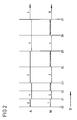
- Figure 2 shows an example of a flow chart of the method according to the invention according to claim 1.
- the arrow marked with the letter X indicates the chronological sequence of the process and the process steps.
- the individual times are marked with the letter number combinations (Z0, Z1, Z2, ).
- Z0, Z1, Z2, ...) At each time (Z0, Z1, Z2, ...) and each time period it is entered whether and which output, characterized by the letter number combinations (A0, A1, A2, 7), is carried out and whether averaging and which averaging takes place, characterized by the letter number combinations (M1, M2, M3 ).
- the device according to the invention is z. B. by a positive potential at the first terminal (H), which is caused by switching on the lighting system or switching on the ignition of the vehicle, switched on via the switch-on device (E).
- the first switching device (S1) switches the first timer (ZG1) to the shortest filter time constant and the second switching device (S2) switches the difference signal from the difference generator (D) directly to the output of the second switching device, which is connected to the comparator (K) to give the difference signal directly to the actuator.
- the difference signal is output directly (A0) to the actuating device.
- the averaging (M1) is carried out via the first filter time constant, which is completed at time (Z1), that is to say when the filter time constant has expired.
- the second switching device (S2) is controlled by the first timing element (ZG1) and switches off the direct output and switches to the output of the stored difference signal.
- the memory (SP) is switched to output and at the same time the first timer (ZG1) and the second timer (ZG2) are reset so that the shortest filter time constant can run again.
- the output (A1) of the averaging (M1) thus takes place from the time (Z1).
- the averaging (M2) takes place via this first shortest filter time constant.
- the counter (Z) receives a signal from the first timing element (ZG1), as a result of which the counting is ended and the averaging is completed.
- the output (A1) continues until the delay time determined by the second timer (ZG2), which here corresponds to the first filter time constant, has elapsed, whereupon a signal from the second timer (ZG2) to the memory (SP) at the start of the output (A2) is given. This corresponds to the time (Z3).
- the second switching element (ZG2) controls the first switching device (S1), which in turn controls the first timing element (ZG1) such that the next longer filter time constant is switched on.
- the first timer (ZG1) has only two first sub-timer elements, so that in addition to the direct output, only two filter time constants can be switched on. For this reason, the next higher one at time (Z5) Filter time constant switched on, but the device remains at the longest possible filter time constant.
- the output (A3) of the averaging (M3) thus takes place over the longest filter time constant plus the delay time up to the point in time (Z7) specified by the second timing element (ZG2).
- the averaging (M4) takes place from the time (Z5) to the time (Z6) and is suspended from the time (Z6) to the time (Z7). This process sequence is then repeated continuously.
- the first filter time constant can be, for example, about 8 seconds, while the second filter time constant can be, for example, about 16 seconds.
- the filter time constants can also be selected to be smaller or larger and can thus be set depending on the requirements.
- the first timing element (ZG1) and the second timing element (ZG2) can have a larger number of first and second sub-timing elements, so that the gradations can be selected to be smaller and more precise regulation can be achieved. It is possible that the shortest filter time constant corresponds to the distance of the clock signals from the first clock signal generator (T1).
- the averaging is not suspended by the second timer (ZG2), so that the output and the averaging take place continuously and thus an approximately dynamic regulation of the headlight range or the level of the vehicle is achieved.
- the change in the operating mode can be a positive and / or negative acceleration of the vehicle.
- the change in the operating mode of the vehicle can also be predetermined by the change between the journey and the position of the vehicle. It can be predetermined by opening and closing the doors and / or flaps of the vehicle or else can also be specified by the driver operating a switch.
- the shortest filter time constant is activated via the first switching device (S1) and the difference signal is switched directly to the output of the second switching device, which is connected to the actuating device, via the second switching device (S2).
- the method is recorded at the point in time (Z0) at which the differential signal is output directly to the actuating device, but no averaging is carried out until the operating mode of the vehicle changes again. This would be e.g. B. closing all doors and / or flaps of the vehicle or starting the journey of the vehicle.
- the device If the change in the operating mode of the vehicle is predetermined by a positive and / or negative acceleration of the vehicle, it is necessary so that the device is not switched to the direct output at each acceleration that a threshold value for the positive and / or negative acceleration is exceeded must be done before the differential signal is output directly. In addition, it may be necessary for the threshold value to be exceeded for a predetermined time before switching over to direct output. In this case too, the device and the method are recorded at time (Z0) until the threshold value is undershot. The procedure then proceeds as described above.
- the filtered difference signal is present at the output as a constant value at the output of the second switching device (S2).
- This constant output signal is compared with a periodically changing signal, which here is, for example, a sawtooth signal, so that after the comparison of the two signals an output signal is obtained which has a constant pulse-period ratio.
- This signal is filtered, the filtering from a Rectification exists, which is carried out to eliminate any interference from the signal.
- the filtered signal is applied to one or more position control loops (L) which control one or more motors contained in actuators, the actuators causing a change in the position of the headlights or the level of the body of the vehicle.
- L position control loops
- the clock generated by the first clock signal generator (T1) and fed to the timing elements has an example of a distance of 0.25 seconds.
- the clock generated by the second clock signal generator (T2), which is passed on to the comparator (K), is here, for example, at a distance of one millisecond.
- the result is a method according to the invention and a device for carrying out this method, in which the best possible adaptation of the control of the headlight range or the level of the vehicle to the operating time or to changes in the operating mode of the vehicle is achieved in a simple and inexpensive manner and the safety at the operation of the vehicle is increased.
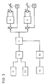
- Figure 3 shows a block diagram of an inventive device for performing the method according to claim 20.
- a first sensor (F1) and a second sensor (F2) are electrically conductively connected to a difference generator (D).
- the first sensor (F1) can be arranged on the front axle and the second sensor (F2) on the rear axle of the motor vehicle.
- the first sensor (F1) delivers a signal that is proportional to the position of the vehicle body relative to the front axle.
- the second sensor (F2) provides a signal that is proportional to the position of the vehicle body relative to the rear axle.
- the difference generator (D) generates a difference signal from these pending signals that is suitable for actuating actuating devices that adjust the actuating elements (SE) to adjust the headlight range or the level of the vehicle.
- the difference generator (D) is followed by a filter (F), which has a mean value generator, which enables the control devices to be controlled with a new, constant control signal only after a predetermined variable filter time constant, thereby increasing the service life of the control devices and the control elements (SE). is increased.
- a filter which has a mean value generator, which enables the control devices to be controlled with a new, constant control signal only after a predetermined variable filter time constant, thereby increasing the service life of the control devices and the control elements (SE). is increased.
- the filter (F) is electrically conductively connected to an acceleration sensor (BG), which in turn is electrically conductively connected to a vehicle speed sensor (FG).
- BG acceleration sensor
- FG vehicle speed sensor
- the vehicle speed sensor (FG) provides the accelerometer (BG) with a signal that is proportional to the vehicle speed.
- the driving speed signal can be formed by a mechanical device or else by an electronic device.
- the acceleration sensor (BG) has a differentiator that forms an acceleration signal from the vehicle speed signal.
- This acceleration signal is fed to the filter (F) which, for. B. has a memory which, depending on the pending acceleration signals from the acceleration sensor (BG), switches on the filter time constants which become effective continuously or in predetermined steps.
- the memory can have also stored a number of values for the pending acceleration signals, which are used to average over the pending acceleration, as a result of which the filter time constants are determined.
- the output of the filter (F) is connected in an electrically conductive manner, for example, to two actuating devices, each of which consists of a subtractor (SB), a controller (R), a motor (M), an actuating element (SE) and a position signal transmitter (LG) are.
- the output of the filter (F) can also be connected to a larger number of actuating devices.
- Each actuator has the following structure.
- the signal formed by the filter (F) is fed to the subtractor (SB). This signal has, for example, a positive sign.
- the subtractor (SB) is connected in an electrically conductive manner to a controller which controls a motor (M). As indicated by a broken line in FIG.
- the motor (M) is connected to an actuating element (SE) which is adjusted in its position in accordance with the control of the motor (M) by the controller (R).
- SE actuating element
- the control element (SE) is connected to a position signal transmitter (LG) which, for. B. can be a potentiometer, but can also be designed as a counting circuit for the movement of the motor (M) or the control element (SE).
- LG position signal transmitter
- the position signal transmitter (LG) is electrically conductively connected to the subtractor, so that a closed position control loop is formed.
- the signal from the position signal generator (LG) is fed to the subtractor (SB) as an example with a negative sign.
- the first sensor (F1) and the second sensor (F2) supply the difference generator (D) with signals which depend on the position of the vehicle body relative to the front and rear axles.
- the filter (F) therefore supplies the filter (F) with a corresponding signal.
- the filter (F) switches on a filter time constant which has a predetermined limit value, that is to say that the greatest filter time constant is switched on in this operating mode of the vehicle.
- This filter time constant can be approximately 1 second, for example, but it can also be a few seconds. This ensures that, for. B.
- the loading range or the level of the vehicle is adjusted with sufficient speed during a loading process in the state of the vehicle.
- an acceleration signal is formed on the basis of the vehicle speed signal from the vehicle speed sensor (FG) by the acceleration sensor (BG), depending on which the filter (F) changes the filter time constants.
- the filter time constant is continuously or discontinuously reduced to shorter times with increasing positive and with increasing negative acceleration of the vehicle and continuously or discontinuously increased to longer times with decreasing positive and with decreasing negative acceleration.
- the filter time constant assumes a very small value at very strong accelerations, which usually occur at low driving speeds and in particular when starting and braking the vehicle, which ensures that the relative movement of the vehicle body to the wheel axles quickly and is safely compensated and the light range so quickly and it is safely regulated that there is neither dazzling oncoming traffic nor a reduction in visibility.
- the change in the filter time constant with the change in the acceleration of the vehicle can take place continuously, but it can also take place in stages.
- a particularly simple embodiment is obtained if predetermined ranges of positive and negative acceleration are each assigned a filter time constant.
- the filter time constants can be stored in a map memory.
- the method has a particularly simple embodiment if, starting with an acceleration equal to zero with increasing and decreasing positive or negative acceleration when predetermined acceleration levels are exceeded, the filter time constant is increased or decreased by a predetermined factor, so that the filter is simpler and less expensive Execution only has to have threshold detection devices which, depending on the acceleration signals present, actuate switching devices which change the filter time constant by a respectively predetermined factor.
- the filter time constant can be determined in such a way that the number of values over which the averaging is varied is varied as a function of the pending acceleration signals, so that the filter time constant is continuous with each change in the acceleration signals from the acceleration sensor or can be changed discontinuously depending on the acceleration signal.
- the mean value to be formed results from the number (n) of values over which the mean is averaged, the unfiltered difference signal and the previously formed mean value (mean value (k-1)) according to the following recursion formula :
- the mean value (mean value (k)) is present at the output of the filter (F) and directly controls the control devices.
Description
Die Erfindung betrifft Verfahren zur Regelung der Leuchtweite oder des Niveaus eines Fahrzeugs gemäß dem Oberbegriff des Anspruchs 1 und des Anspruchs 16, eine Einrichtung gemäß dem Oberbegriff des Anspruchs 9 und eine Einrichtung zur Durchführung des Verfahrens gemäß dem Oberbegriff des Anspruchs 20.The invention relates to a method for regulating the lighting range or the level of a vehicle according to the preamble of
Eine Einrichtung zur Durchführung eines Verfahrens dieser Art ist aus der deutschen Offenlegungsschrift DE-OS 31 10 094 bekannt.A device for carrying out a method of this type is known from the German published application DE-OS 31 10 094.
Fühler, die die relative Stellung der Karosserie eines Fahrzeugs zu den Fahrzeugachsen oder Fahrzeugrädern messen, sind an einem Analog-Multiplexer angeschlossen, der die von den Fühlern anliegenden Signale über einen Analog/Digital-Wandler einem Mikroprozessor zuführt. Eine Filterung der anliegenden Signale erfolgt, indem in einem festgelegten Zeitabstand eine Mittelwertbildung der Signale durchgeführt wird. Dazu wird die Anzahl der einzubeziehenden Meßwerte vorgegeben. Aus den Mittelwerten wird dann für je ein Fühlerpaar ein Differenzsignal gebildet, das einem Scheinwerfereinstellwert entspricht. Jedes dieser Differenzsignale wird einem Digital/Analog-Wandler zugeführt, der über je einen nachgeschalteten Operationsverstärker mit einer Scheinwerferstelleinrichtung verbunden ist. In Abhängigkeit von dem Vorzeichen der Differenzsignale werden somit Stellelemente vor- oder zurückbewegt und Scheinwerferlageregister im Mikroprozessor hoch- oder heruntergezählt. Das Differenzsignal muß zudem einen vorgegebenen Schwellwert überschreiten, bevor die Scheinwerferstelleinrichtung betätigt wird.Sensors that measure the relative position of the body of a vehicle relative to the vehicle axles or vehicle wheels are connected to an analog multiplexer, which feeds the signals from the sensors to a microprocessor via an analog / digital converter. The applied signals are filtered by averaging the signals at a specified time interval. For this, the number of measured values to be included is specified. A difference signal corresponding to a headlight setting value is then formed from the mean values for each pair of sensors. Each of these differential signals is fed to a digital / analog converter, which is connected to a headlamp actuating device via a downstream operational amplifier. Depending on the sign of the difference signals, actuating elements are moved forwards or backwards and headlight position registers in the microprocessor are counted up or down. The difference signal must also exceed a predetermined threshold value before the headlight actuating device is actuated.
Nachteilig erweist sich hierbei, daß die Mittelung nur in einem festgelegten Zeitabstand erfolgt, wodurch eine Anpassung an wechselnde Betriebsbedingungen des Fahrzeugs nicht erfolgt und somit eine Blendgefahr und eine Gefährdung des Gegenverkehrs nicht ausgeschlossen ist. In diesem Zusammenhang erweist sich als nachteilig, wenn wie hier der Zeitabstand für die Mittelung auf z. B. eine Minute festgelegt wird, weil bei diesem Zeitabstand kurzzeitige Änderungen nicht erfaßt und korrigiert werden können.It proves disadvantageous here that the averaging takes place only at a fixed time interval, as a result of which adaptation to changing operating conditions of the vehicle does not take place and thus a risk of glare and a risk to oncoming traffic is not excluded. In this context, it turns out to be disadvantageous if, as here, the time interval for averaging to z. B. a minute is set because short changes at this time interval can not be detected and corrected.
Weiterhin ist nachteilig, daß die Anzahl der bei der Mittelung berücksichtigten Signale experimentell vorgegeben werden, da dies umfangreiche Untersuchungen erfordert, die nicht einfach und kostengünstig durchführbar sind.Another disadvantage is that the number of signals taken into account in the averaging is predetermined experimentally, since this requires extensive investigations that are not easy and inexpensive to carry out.
Aus der deutschen Offenlegungsschrift DE-OS 31 29 891 ist eine Einrichtung zur Durchführung eines Verfahrens der genannten Art vorbekannt, die zwei Fühler aufweist, die Signale erzeugen, die von der relativen Stellung der Karosserie zu den Rädern abhängen. Diese Signale werden einem Differenzbildner zugeführt, der ein Differenzsignal bildet, welches an einen Filter weitergeleitet wird. Der Filter weist neben einem als RC-Glied ausgebildeten Tiefpaßfilter, das unerwünschte Frequenzen des Differenzsignals sperrt, Filterelemente auf, die eine variable Charakteristik der Frequenzabtrennung in Abhängigkeit von der Amplitude der Signale der Fühler vorgeben. Die Filterelemente sind als Schwellwertelemente, insbesondere Gleichrichter, ausgebildet, die eine obere und untere Amplitudenschwelle festlegen. Das gefilterte Signal wird an eine Steuervorrichtung weitergeleitet, die mit Stellelementen zur Einstellung von Scheinwerfern verbunden sind.From the German published application DE-OS 31 29 891 a device for performing a method of the type mentioned is known, which has two sensors that generate signals that depend on the relative position of the body to the wheels. These signals are fed to a difference generator which forms a difference signal which is passed on to a filter. In addition to a low-pass filter designed as an RC element, which blocks unwanted frequencies of the differential signal, the filter has filter elements which specify a variable characteristic of the frequency separation as a function of the amplitude of the signals from the sensors. The filter elements are designed as threshold value elements, in particular rectifiers, which define an upper and lower amplitude threshold. The filtered signal is forwarded to a control device which is connected to control elements for adjusting headlights.
Als nachteilig erweist sich hierbei, daß die Amplitudenschwellwerte nur auf zwei Werte fest einstellbar sind und die Frequenz des Filters nur geringfügig veränderbar ist, wodurch häufig eine optimale Anpassung der Einrichtung an unterschiedliche Betriebsarten des Fahrzeugs nicht erfolgen kann. Zudem wird bei jedem überschreiten der Schwellwerte durch das Differenzsignal eine Einstellung der Scheinwerfer vorgenommen, wodurch die Lebensdauer der Stellelemente herabgesetzt wird.It proves to be disadvantageous here that the amplitude threshold values can only be set permanently to two values and the frequency of the filter can only be changed slightly, which often results in an optimal adaptation of the Can not be set up to different modes of operation of the vehicle. In addition, each time the threshold values are exceeded, the differential signal adjusts the headlights, thereby reducing the service life of the control elements.
Aus der deutschen Offenlegungsschrift DE-OS 29 33 308 ist eine Einrichtung zur Regelung der Leuchtweite bekannt, bei der ein erster Meßwert, der die relative Lage der Fahrzeugkarosserie zu einer festen Ebene angibt, bestimmt und abgespeichert wird und bei der ein zweiter Meßwert, der die relative Lage der Fahrzeugkarosserie zu der gleichen festen Ebene nach einer Beladung angibt, bestimmt wird. Der Vergleich der beiden Meßwerte liefert ein Signal, dessen Größe ein Maß für die erforderliche Verschwenkung der Scheinwerfer ist. Als Meßwertgeber dient dabei ein Pendel oder ein Doppelpendel. Die Bestimmung der Meßwerte ist durch das öffnen und Schließen der Türen oder Klappen des Fahrzeugs ein- und ausschaltbar.From the German patent application DE-OS 29 33 308 a device for controlling the light range is known in which a first measured value, which indicates the relative position of the vehicle body to a fixed plane, is determined and stored, and in which a second measured value, which relative position of the vehicle body to the same fixed plane after loading indicates. The comparison of the two measured values provides a signal, the size of which is a measure of the required pivoting of the headlights. A pendulum or a double pendulum serves as the measuring sensor. The determination of the measured values can be switched on and off by opening and closing the doors or flaps of the vehicle.
Als nachteilig erweist sich hierbei, daß die Einstellung der Scheinwerfer nur im Stand des Fahrzeugs erfolgt und relative Lageänderungen der Fahrzeugkarosserie zu den Radachsen während der Fahrt unberücksichtigt bleiben.It proves to be disadvantageous here that the headlights are adjusted only when the vehicle is stationary and relative changes in position of the vehicle body relative to the wheel axles are not taken into account while driving.
Aus der deutschen Offenlegungsschrift DE-OS 34 18 646 ist ein Verfahren und eine Einrichtung zur Regelung des Niveaus eines Fahrzeugs der genannten Art bekannt.From the German published application DE-OS 34 18 646 a method and a device for regulating the level of a vehicle of the type mentioned is known.
Die Einrichtung weist hydraulische Federungs- bzw. Aufhängungseinheiten zwischen den Achsen und der Karosserie des Fahrzeugs auf, die zum einen eine Federung und Dämpfung der Karosseriebewegungen und zum anderen eine Einstellung des Niveaus des Fahrzeugs ermöglichen. Zur Ermittlung der relativen Stellung der Fahrzeugkarosserie zu der Hinterachse und der Vorderachse weist die Einrichtung an der Vorderachse und der Hinterachse je einen Karosseriehöhenfühler auf, die einer Niveauregulierungseinheit jeweils ein Signal liefern, das die Stellung der Karosserie zu den Achsen angibt. Entsprechend dieser anstehenden Signale von den Karosseriehöhenfühlern, regelt die Niveauregulierungseinheit die Erzeugung von Druckluft und die Zuführung von Druckluft zu den Federungs- bzw. Aufhängungseinheiten. Zudem ist die Niveauregulierungseinheit mit einem Fahrgeschwindigkeitsfühler verbunden, so daß der Zeitabstand für die Einleitung einer Niveauregulierung und damit die Filterzeitkonstante für eine Mittelwertbildung der Signale von den Karosseriehöhenfühlern von der Fahrgeschwindigkeit abhängig ist. Unter einem vorgegebenen Schwellwert für die Fahrgeschwindigkeit ist der Zeitabstand für die Einleitung einer Niveauregulierung und damit die Filterzeitkonstante für eine Mittelwertbildung kürzer als für eine Fahrgeschwindigkeit oberhalb des vorgegebenen Schwellwertes.The device has hydraulic suspension or suspension units between the axles and the body of the vehicle, which on the one hand allow suspension and damping of the body movements and on the other hand to adjust the level of the vehicle. To determine the relative position of the vehicle body to the rear axle and the front axle, the device has a body height sensor on the front axle and the rear axle, each of which supplies a signal to a level control unit. which indicates the position of the body in relation to the axles. In accordance with these pending signals from the body height sensors, the level control unit regulates the generation of compressed air and the supply of compressed air to the suspension or suspension units. In addition, the level control unit is connected to a vehicle speed sensor, so that the time interval for the initiation of level control and thus the filter time constant for averaging the signals from the body height sensors is dependent on the vehicle speed. Below a predefined threshold value for the vehicle speed, the time interval for initiating level control and thus the filter time constant for averaging are shorter than for a vehicle speed above the predetermined threshold value.
Der Zeitabstand für die Einleitung einer Niveauregulierung wird zudem dann verkürzt, wenn der Vorgang der Niveauregulierung bei einer Fahrgeschwindigkeit unterhalb des vorgegebenen Schwellwertes mit einem zugehörigen kurzen Zeitabstand eingeleitet wurde und der Vorgang der Niveauregulierung jedoch beendet wird, wenn das Fahrzeug eine Fahrgeschwindigkeit oberhalb des vorgegebenen Schwellwertes angenommen hat, wodurch erreicht wird, daß das Niveau des Fahrzeugs möglichst ohne große Verzögerung bei einem Beschleunigungsvorgang auf den vorgegebenen Sollwert eingestellt wird.The time interval for initiating level control is also shortened if the level control process was initiated at a driving speed below the specified threshold value with an associated short time interval and the level control process is ended, however, when the vehicle assumes a driving speed above the specified threshold value has, whereby it is achieved that the level of the vehicle is set as possible without great delay in an acceleration process to the predetermined target value.
Dies wird hier dadurch erreicht, daß Luftfederungskammern der Federungs- bzw. Aufhängungseinheiten mit Luftfederungshilfskammern von der Niveauregulierungseinheit in Verbindung gesetzt werden können, so daß die Federkonstante verringert oder erhöht wird. Sind die Luftfederungskammern nicht mit den Luftfederungshilfskammern verbunden, stellt sich eine größere Federkonstante ein. Die Verbindung und Trennung der Luftfederungskammern mit und von den Luftfederungshilfskammern zur Veränderung der Einstellung der Härte der Federung erfolgt hier über Magnetmechanismen an den Federungs- bzw. Aufhängungseinheiten.This is achieved here in that air suspension chambers of the suspension or suspension units can be connected to air suspension auxiliary chambers by the level control unit, so that the spring constant is reduced or increased. If the air suspension chambers are not connected to the air suspension auxiliary chambers, a larger spring constant is set. The connection and disconnection of the air suspension chambers with and from the air suspension auxiliary chambers for changing the setting of the hardness of the suspension takes place here Magnetic mechanisms on the suspension or suspension units.
Als nachteilig erweist sich hierbei, daß nur ein Schwellwert für die Fahrgeschwindigkeit vorgegeben wird, weil somit die Zeitabstände für die Einleitung eines Niveauregulierungsvorgangs, durch die Vorgabe von nur zwei Zeitabständen, nur ungenügend den jeweiligen Fahrgeschwindigkeiten angepaßt sind und der Übergang von dem einen Zeitabstand zu dem anderen Zeitabstand sehr groß ist.It proves to be disadvantageous that only a threshold value for the driving speed is specified, because the time intervals for initiating a level control process are only insufficiently adapted to the respective driving speeds due to the specification of only two time intervals, and the transition from one time interval to the other other time interval is very large.
Dadurch, daß der geringste Zeitabstand für die Einleitung eines Niveauregulierungsvorgangs hier auf 1,5 sec. festgelegt ist, ergibt sich insbesondere der Nachteil, daß selbst bei sehr langsamen Fahrgeschwindigkeiten große und schnell ablaufende Änderungen des Niveaus durch die Regeleinrichtung nicht ausgeglichen werden können und somit nur eine quasi-statische Regelung des Niveaus des Fahrzeugs ermöglicht wird, die auf Änderungen der Betriebsart und des Fahrzustands des Fahrzeugs nicht reagieren kann.The fact that the smallest time interval for initiating a level regulation process is set at 1.5 seconds here results in particular in the disadvantage that large and rapid changes in the level cannot be compensated for by the control device, and thus only at very slow driving speeds a quasi-static regulation of the level of the vehicle is made possible, which cannot react to changes in the operating mode and the driving state of the vehicle.
Die Erfindung hat die Aufgabe, ein Verfahren und eine Einrichtung zur Durchführung des Verfahrens zu schaffen, das einfach und kostengünstig durchführbar und herstellbar ist, daß eine an die Betriebsdauer und die jeweiligen unterschiedlichen Betriebsarten angepaßte Regelung der Leuchtweite oder des Niveaus eines Fahrzeugs ermöglicht und die Sicherheit bei dem Betrieb des Fahrzeugs erhöht.The invention has for its object to provide a method and a device for carrying out the method which is simple and inexpensive to carry out and manufacture, and which enables the headlight range or the level of a vehicle to be adapted to the operating time and the respective different operating modes, and to provide security increased in the operation of the vehicle.
Die Aufgabe wird erfindungsgemäß durch die Merkmale des kennzeichnenden Teils des Anspruchs 1 und des Anspruchs 9 gelöst.The object is achieved by the features of the characterizing part of
Dadurch, daß der festgelegte Zeitabstand und die Zeit, über die gemittelt wird, durch eine vorgegebene veränderliche Filterzeitkonstante bestimmt ist, ergibt sich der Vorteil, daß das Verfahren einfach und kostengünstig durchführbar ist und leicht an unterschiedliche Anforderungen anpaßbar ist.The fact that the specified time interval and the time over which averaging is determined by a predetermined variable filter time constant results in the advantage that the method can be carried out simply and inexpensively and can be easily adapted to different requirements.
Vorteilhaft ist es, daß mit fortschreitender Betriebsdauer nach einem Start oder einem Einschalten der Beleuchtungsanlage oder einer Änderung der Betriebsart des Fahrzeugs die Filterzeitkonstante von kürzeren Zeiten auf längere Zeiten erhöht wird, weil so eine an die Betriebsdauer und die jeweiligen unterschiedlichen Betriebsarten angepaßten Regelung der Leuchtweite oder des Niveaus eines Fahrzeugs erreicht wird, die die Blendgefahr des Gegenverkehrs herabsetzt, die eigene Sicht verbessert und somit die Sicherheit bei dem Betrieb des Fahrzeugs erhöht.It is advantageous that the filter time constant is increased from shorter times to longer times with increasing operating time after starting or switching on the lighting system or a change in the operating mode of the vehicle, because in this way a control of the lighting range or adapted to the operating time and the respective different operating modes the level of a vehicle is reached, which reduces the risk of dazzling oncoming traffic, improves one's own view and thus increases safety when operating the vehicle.
Es ist von Vorteil, daß ein erster Taktsignalgeber mit dem ersten Zeitglied verbunden ist, weil somit einfach und kostengünstig eine Filterzeitkonstante festlegbar ist.It is advantageous that a first clock signal generator is connected to the first timing element, because a filter time constant can thus be determined simply and inexpensively.
In diesem Zusammenhang ist es vorteilhaft, daß das erste Zeitglied über eine vorgegebene Anzahl aufeinanderfolgende erste Unterzeitglieder verfügt, wodurch die Filterzeitkonstante einfach verändert werden kann und eine Anpassung der Einrichtung an unterschiedliche Betriebsarten des Fahrzeugs möglich ist.In this context, it is advantageous that the first timing element has a predetermined number of successive first sub-timing elements, as a result of which the filter time constant can be changed easily and the device can be adapted to different operating modes of the vehicle.
Vorteilhaft ist es, daß die ersten Unterzeitglieder Filterzeitkonstanten vorgeben, die in der Aufeinanderfolge der ersten Unterzeitglieder ansteigen, weil so mit steigender Betriebsdauer durch ein Erhöhen der Filterzeitkonstante kurzzeitige Störungen herausgefiltert werden, wodurch die Sicherheit bei dem Betrieb des Fahrzeugs erhöht wird, da bei diesen kurzzeitigen Störungen keine Korrektur der Scheinwerfereinstellung vorgenommen wird und somit eine Fehleinstellung der Scheinwerfer vermieden wird und die Lebensdauer der Stellelemente heraufgesetzt wird.It is advantageous that the first sub-time elements specify filter time constants, which increase in the sequence of the first sub-time elements, because as the operating time increases, short-term disturbances are filtered out by increasing the filter time constant, which increases the safety during the operation of the vehicle, since these have short-term effects Malfunctions, no correction of the headlight setting is carried out and thus incorrect setting of the headlights is avoided and the service life of the adjusting elements is increased.
Dadurch, daß die ersten Unterzeitglieder mit einer ersten Schalteinrichtung verbunden sind und daß die erste Schalteinrichtung Schalter aufweist, die mit den ersten Unterzeitgliedern verbunden sind, ergibt sich der Vorteil, daß mit zunehmender Betriebsdauer und bei einer Änderung der Betriebsart des Fahrzeugs die Schalteinrichtung von den Unterzeitgliedern angesteuert wird und diese Schalter wiederum die Unterzeitglieder einschalten und ausschalten, wodurch jeweils die Filterzeitkonstante eingeschaltet wird, die der jeweiligen Betriebsdauer und der jeweiligen Betriebsart am besten entspricht, was die Sicherheit bei dem Betrieb des Fahrzeugs erhöht.The fact that the first sub-time elements are connected to a first switching device and that the first switching device has switches which are connected to the first sub-time elements gives the advantage that that with increasing operating time and with a change in the operating mode of the vehicle, the switching device is actuated by the sub-time elements and these switches in turn switch the sub-time elements on and off, whereby the filter time constant is switched on which corresponds best to the respective operating time and the respective operating mode, which is the Increased safety when operating the vehicle.
Vorteilhaft ist es, daß die ersten Unterzeitglieder des ersten Zeitglieds elektrisch leitend mit dem Filter verbunden sind, wodurch einfach und kostengünstig die jeweils wirkende Filterzeitkonstante dem Filter als Schaltsignal zugeführt wird, das die Dauer der Mittelwertbildung und den Zeitabstand bestimmt, nach dessen Ablauf eine neue Mittelwertbildung begonnen wird.It is advantageous that the first sub-time elements of the first time element are electrically conductively connected to the filter, as a result of which the filter time constant acting in each case is supplied simply and inexpensively to the filter as a switching signal which determines the duration of the averaging and the time interval after which a new averaging takes place is started.
Weitere vorteilhafte Ausgestaltungen und Weiterbildungen des erfindungsgemäßen Verfahrens und der Einrichtung zur Durchführung des Verfahrens ergeben sich aus den Unteransprüchen.Further advantageous refinements and developments of the method according to the invention and the device for carrying out the method result from the subclaims.
Dadurch, daß nach der Differenzbildung der Signale von der Vorderachse und der Hinterachse eine Spannungs-Frequenzumsetzung erfolgt, ergibt sich der Vorteil, daß das Differenzsignal als ein digitales Frequenzsignal vorliegt und somit einfach weiter verarbeitbar ist.The fact that, after the difference between the signals from the front axle and the rear axle, a voltage-frequency conversion takes place, there is the advantage that the difference signal is present as a digital frequency signal and is therefore easy to process further.
Vorteilhaft ist, daß die Filterung aus einer Zählung, Aufsummierung und Speicherung des Differenzsignals besteht, wobei die Zählung über die jeweils wirksame Filterzeitkonstante erfolgt, weil so auf einfache und kostengünstige Weise eine Mittelung des Differenzsignals durchgeführt wird und durch die Abspeicherung des Differenzsignals eine verspätete Ausgabe ermöglicht wird. In diesem Zusammenhang erweist sich als vorteilhaft, daß die Zählung durch eine Teilung der Frequenz des Differenzsignals vor der Zählung beeinflußt wird, die von der jeweils wirksamen Filterzeitkonstante abhängt, und daß nach Ablauf der jeweils wirksamen Filterzeitkonstante die Zählung beendet wird und das aufsummierte, gespeicherte Differenzsignal ausgegeben wird, weil so das abgespeicherte Differenzsignal auch bei unterschiedlich langen Filterzeitkonstanten ein festes Maß für die Einstellung der Scheinwerfer oder des Niveaus des Fahrzeugs vorgibt und die Ausgabe zu einem definierten Zeitpunkt erfolgt.It is advantageous that the filtering consists of counting, summing up and storing the difference signal, the counting taking place over the respectively effective filter time constant, because in this way the difference signal is averaged in a simple and inexpensive manner and enables a delayed output by storing the difference signal becomes. In this context, it proves advantageous that the counting by dividing the frequency of the difference signal is influenced before the count, which depends on the respectively effective filter time constant, and that after the respective effective filter time constant has expired, the counting is ended and the summed, stored difference signal is output, because the stored difference signal is a fixed measure of the even with filter time constants of different lengths Setting the headlights or the level of the vehicle specifies and the output takes place at a defined time.
Weiterhin ist es vorteilhaft, daß die jeweils wirksame Filterzeitkonstante aus einem Taktsignal durch Teilung oder Multiplikation abgeleitet wird, wodurch die Filterzeitkonstanten einfach und kostengünstig bereitgestellt werden.It is also advantageous that the respectively effective filter time constant is derived from a clock signal by division or multiplication, as a result of which the filter time constants are provided simply and inexpensively.
Dadurch, daß nach Ablauf einer Filterzeitkonstante die nächst längere Filterzeitkonstante wirksam geschaltet wird, ergibt sich der Vorteil, daß in Abhängigkeit von der Betriebsdauer des Fahrzeugs die Mittelung in vorgegebenen, länger werdenden Zeitabschnitten erfolgt, was zu einer Schonung der Stellelemente beiträgt und die Sicherheit bei dem Betrieb des Fahrzeugs erhöht.The fact that after the expiration of a filter time constant the next longer filter time constant is activated, there is the advantage that, depending on the operating time of the vehicle, the averaging takes place in predetermined, longer periods of time, which contributes to the protection of the control elements and the safety Operation of the vehicle increased.
Vorteilhaft ist es, daß die Ausgabe des aufsummierten, gespeicherten Differenzsignals nach abgeschlossener Zählung um die jeweils wirksame Filterzeitkonstante verzögert erfolgt, wodurch die Ansteuerung der Stellelemente in längeren Zeitabständen erfolgt, was die Lebensdauer der Stellelemente erhöht. Es ist von Vorteil, daß das aufsummierte, gespeicherte Differenzsignal als konstanter Wert ausgegeben wird, bis nach dem Ablauf der Filterzeitkonstante und der durch die Filterzeitkonstante bestimmten Verzögerung ein neues gespeichertes Signal ausgegeben wird, weil somit die Einstellung der Scheinwerfer oder des Niveaus des Fahrzeugs bis zu einer neuen Ausgabe eines abgespeicherten Signals auf einen konstanten Wert gehalten wird.It is advantageous that the output of the summed, stored difference signal is delayed after the counting is completed by the respectively effective filter time constant, as a result of which the control elements are actuated at longer time intervals, which increases the service life of the control elements. It is advantageous that the accumulated, stored difference signal is output as a constant value until after the expiry of the filter time constant and the delay determined by the filter time constant a new stored signal is output, because thus the adjustment of the headlights or the level of the vehicle up to a new output of a stored signal is kept at a constant value.
Dadurch, daß bei einem Start oder bei einem Einschalten der Beleuchtungsanlage oder bei einer Änderung der Betriebsart des Fahrzeugs die kürzeste Filterzeitkonstante oder eine kürzere Filterzeitkonstante als die jeweils wirksame Filterzeitkonstante eingeschaltet wird, ergibt sich der Vorteil, daß die Regelung der Leuchtweite oder des Niveaus des Fahrzeugs entsprechend der Änderung der Betriebsart des Fahrzeugs oder dem Einschalten der Beleuchtungsanlage schneller erfolgt, wodurch die Sicherheit bei dem Betrieb des Fahrzeugs erhöht wird.The fact that the shortest filter time constant or a shorter filter time constant than the respectively effective filter time constant is switched on when the lighting system is started or when the lighting system is switched on or when the operating mode of the vehicle is changed, has the advantage that the control of the lighting range or the level of the vehicle is obtained in accordance with the change in the operating mode of the vehicle or the switching on of the lighting system, which increases the safety during the operation of the vehicle.
Vorteilhaft ist es, daß das Differenzsignal bei dem Einschalten der kürzesten Filterzeitkonstante unter Umgehung der Filterung direkt ausgegeben wird, wodurch eine unverzögerte Ansteuerung der Stellelemente erreicht wird, die bei Beladungsänderungen des Fahrzeugs oder bei Einschalten der Beleuchtungsanlage erforderlich ist.It is advantageous that the differential signal is output directly when the shortest filter time constant is switched on, bypassing the filtering, as a result of which the actuating elements are activated without delay, which is required when the vehicle is loaded or the lighting system is switched on.
In diesem Zusammenhang ist es vorteilhaft, daß nach dem Ablauf dieser Filterzeitkonstante, während der gleichzeitig eine Filterung erfolgte, dieselbe Filterzeitkonstante nocheinmal eingeschaltet wird und gleichzeitig eine Ausgabe des gefilterten gespeicherten Differenzsignals erfolgt, weil auf diese Weise dafür gesorgt wird, daß die Stellelemente durch einen konstanten Ausgabewert angesteuert werden und gleichzeitig eine neue Mittelung über die gleiche Filterzeitkonstante erfolgt, deren abgespeicherter Wert mit Verzögerung ausgegeben wird, wobei durch die gewählte kurze Filterzeitkonstante eine möglichst schnelle Regelung gewährleistet wird.In this context, it is advantageous that after the expiry of this filter time constant, during which filtering has taken place, the same filter time constant is switched on again and at the same time the filtered stored difference signal is output, because this ensures that the control elements are controlled by a constant Output value are controlled and at the same time a new averaging takes place over the same filter time constant, the stored value of which is output with a delay, with the selected short filter time constant ensuring the fastest possible regulation.
Es ist von Vorteil, wenn eine Änderung der Betriebsart durch einen vorgegebenen Schwellwert für eine negative Beschleunigung des Fahrzeugs bestimmt ist, wodurch bei einem starken Abbremsen des Fahrzeugs, das eine Nachregelung der Einstellung der Scheinwerfer oder des Niveaus des Fahrzeugs erfordert, die kürzeste oder eine kürzere Filterzeitkonstante eingeschaltet wird, wodurch die Sicherheit bei dem Betrieb des Fahrzeugs erhöht wird. In diesem Zusammenhang ist es vorteilhaft, daß eine Änderung der Betriebsart des Fahrzeugs durch einen vorgegebenen Schwellwert für eine positive Beschleunigung des Fahrzeugs bestimmt ist, wodurch auch hier eine sofortige kurzzeitige Nachregelung erfolgt. Man kann eine nach dem überschreiten der Schwellwerte eingeschaltete direkte Ausgabe erst dann abschalten, wenn die Schwellwerte unterschritten werden, wodurch bei einem langanhaltenden Beschleunigungsvorgang keine längere Filterzeitkonstante aktiviert wird, was die Sicherheit bei dem Betrieb des Fahrzeugs erhöht. Dadurch, daß die direkte Ausgabe erst dann erfolgt, wenn die Schwellwerte über eine vorgegebene Zeit überschritten werden, ergibt sich der Vorteil, daß nicht bei jeder kurzzeitigen starken Bremsung die direkte Ausgabe eingeschaltet wird.It is advantageous if a change in the operating mode is determined by a predetermined threshold value for a negative acceleration of the vehicle, so that when the vehicle brakes heavily and requires the headlights or the level of the vehicle to be readjusted, the shortest or a shorter one Filter time constant is turned on, which makes the Safety in the operation of the vehicle is increased. In this context, it is advantageous that a change in the operating mode of the vehicle is determined by a predetermined threshold value for a positive acceleration of the vehicle, as a result of which an immediate brief readjustment also takes place here. A direct output that is switched on after the threshold values have been exceeded can only be switched off when the threshold values are undershot, as a result of which no longer filter time constant is activated in the case of a long-lasting acceleration process, which increases the safety during operation of the vehicle. The fact that the direct output only takes place when the threshold values are exceeded for a predetermined time has the advantage that the direct output is not activated with every brief, heavy braking.
Es ist von Vorteil, daß das ausgegebene Differenzsignal mit einem periodisch sich ändernden Signal verglichen wird, wodurch man ein Ausgangssignal erhält, das ein konstantes Puls-Periodenverhältnis aufweist.It is advantageous that the output difference signal is compared with a periodically changing signal, whereby an output signal is obtained which has a constant pulse-period ratio.
Dadurch, daß die Information des Signals nach dem Vergleich in dem Flankenabstand des entstandenen Puls-Periodenverhältnisses liegt, ergibt sich der Vorteil, daß das Signal, welches an den Stellelementen anliegt, unabhängig von der Spannungsamplitude ist und somit mögliche Fehleinstellungen vermieden werden, die durch Schwankungen der Spannung hervorgerufen werden könnten.The fact that the information of the signal after the comparison lies in the edge spacing of the pulse-period ratio that has arisen has the advantage that the signal which is present on the actuating elements is independent of the voltage amplitude and thus possible incorrect settings which are caused by fluctuations are avoided the tension could be caused.
Vorteilhaft ist es, daß das nach dem Vergleich vorliegende, ein Puls-Periodenverhältnis aufweisende Signal gefiltert wird und einem Lageregelkreis zur Einstellung der Scheinwerfer oder des Niveaus des Fahrzeugs zugeführt wird, weil somit auf einfache und kostengünstige Weise eine Einstellung vorgenommen wird und Störungen des Ausgangssignals herausgefiltert werden.It is advantageous that the signal after the comparison, which has a pulse-period ratio, is filtered and fed to a position control loop for adjusting the headlights or the level of the vehicle, because adjustment is thus carried out in a simple and inexpensive manner and interference in the output signal is filtered out will.
Dadurch, daß der erste Fühler und der zweite Fühler mit dem Differenzbildner verbunden sind, daß der Differenzbildner zum einen direkt mit einer zweiten Schalteinrichtung verbunden ist und zum anderen über einen Spannungs-Frequenzumsetzer, einen Frequenzteiler, einen Zähler und einen Speicher mit der zweiten Schalteinrichtung verbunden ist, ergibt sich der Vorteil, daß das vom Differenzbildner gebildete Differenzsignal zum einen direkt über die zweite Schalteinrichtung ausgegeben werden kann oder aber eine Filterung des Differenzsignals erfolgt, die hier auf einfache und kostengünstige Weise durch ein Aufzählen und Abspeichern des Differenzsignals über eine vorgegebene Filterzeitkonstante realisiert ist.Characterized in that the first sensor and the second sensor are connected to the difference generator, that the difference generator is connected on the one hand directly to a second switching device and on the other hand connected to the second switching device via a voltage-frequency converter, a frequency divider, a counter and a memory there is the advantage that the difference signal formed by the difference generator can be output directly via the second switching device or that the difference signal is filtered, which is realized here in a simple and inexpensive manner by enumerating and storing the difference signal over a predetermined filter time constant is.
Es ist von Vorteil, daß eine erste Klemme mit einer Einschalterkennung verbunden ist, daß die Einschalterkennung mit Rücksetzeingängen der ersten Schalteinrichtung und der zweiten Schalteinrichtung verbunden ist und daß die erste Klemme mit der Klemme 15 oder der Klemme 56 des Fahrzeugs verbunden ist, wodurch bei einem Einschalten der Beleuchtungsanlage oder der Zündung des Fahrzeugs eine direkte Ausgabe des Differenzsignals von dem Differenzbildner erfolgt und gleichzeitig die kürzeste oder eine kürzere Filterzeitkonstante eingeschaltet wird, was die Sicherheit bei dem Betrieb des Fahrzeugs erhöht.It is advantageous that a first terminal is connected to a switch-on identifier, that the switch-on identifier is connected to reset inputs of the first switching device and the second switching device, and that the first terminal is connected to terminal 15 or terminal 56 of the vehicle, which means that at one Switching on the lighting system or the ignition of the vehicle there is a direct output of the difference signal from the difference generator and at the same time the shortest or a shorter filter time constant is switched on, which increases the safety during operation of the vehicle.
In diesem Zusammenhang ist es vorteilhaft, daß die zweite Klemme mit einem Beschleunigungssignalgeber verbunden ist, daß die zweite Klemme elektrisch leitend mit einem Schwellwertschalter verbunden ist und daß der Schwellwertschalter elektrisch leitend mit den Rücksetzeingängen des ersten Zeitglieds, des zweiten Zeitglieds, der ersten Schalteinrichtung, der zweiten Schalteinrichtung, des Zählers und des Speichers verbunden ist, weil somit bei einem Überschreiten eines vorgegebenen Beschleunigungswertes solange eine direkte Ausgabe des Differenzsignals von dem Differenzbildner an die Stellelemente erfolgt, bis der Schwellwert wieder unterschritten wird, wodurch eine Blendgefahr oder eine Sichteinschränkung bei einem Abbrechen des Beschleunigungsvorganges durch die direkte Regelung vermieden wird.In this context, it is advantageous that the second terminal is connected to an acceleration signal generator, that the second terminal is electrically conductively connected to a threshold switch and that the threshold switch is electrically conductively connected to the reset inputs of the first timer, the second timer, the first switching device, the second switching device, the counter and the memory is connected, because if a predetermined acceleration value is exceeded, the difference signal is output directly from the difference generator to the control elements until the threshold value is reached again is undershot, whereby a risk of glare or a view restriction when the acceleration process is interrupted by the direct control is avoided.
Dadurch, daß der Differenzbildner, der Spannungs-Frequenzumsetzer, der Frequenzteiler, der Zähler, der Speicher, die zweite Schalteinrichtung, der zweite Taktsignalgeber, der Komparator, die Einschalterkennung, der erste Taktsignalgeber, das erste Zeitglied, das zweite Zeitglied und die erste Schalteinrichtung teilweise oder ganz in einen Mikroprozessor zusammengefaßt sind, ergibt sich der Vorteil, daß die Einrichtung einfach und kostengünstig herstellbar und realisierbar ist.Characterized in that the difference generator, the voltage-frequency converter, the frequency divider, the counter, the memory, the second switching device, the second clock signal generator, the comparator, the switch-on detection, the first clock signal generator, the first timer, the second timer and the first switching device partially or are combined entirely in a microprocessor, there is the advantage that the device can be produced and implemented simply and inexpensively.
Die Aufgabe wird erfindungsgemäß bei dem Verfahren gemäß Anspruch 16 dadurch gelöst, daß der festgelegte Zeitabstand und die Zeit, über die gemittelt wird, durch eine vorgegebene, veränderliche Filterzeitkonstante bestimmt ist, daß die Filterzeitkonstante mit zunehmender positiver und mit zunehmender negativer Beschleunigung des Fahrzeugs kontinuierlich oder diskontinuierlich auf kürzere Zeiten verkleinert wird, daß die Filterzeitkonstante mit abnehmender positiver und mit abnehmender negativer Beschleunigung kontinuierlich oder diskontinuierlich auf längere Zeiten erhöht wird und daß bei einer positiven und einer negativen Beschleunigung gleich Null die Filterzeitkonstante einen vorgegebenen Grenzwert aufweist.The object is achieved in the method according to claim 16 in that the specified time interval and the time over which averaging is determined by a predetermined, variable filter time constant, that the filter time constant with increasing positive and with increasing negative acceleration of the vehicle continuously or is discontinuously reduced to shorter times, that the filter time constant is increased continuously or discontinuously to longer times with decreasing positive and with decreasing negative acceleration, and that with a positive and a negative acceleration equal to zero, the filter time constant has a predetermined limit value.
Es ist von Vorteil, daß der festgelegte Zeitabstand und die Zeit, über die gemittelt wird, durch eine vorgegebene, veränderliche Filterzeitkonstante bestimmt ist, weil somit das Verfahren einfach und kostengünstig durchführbar ist und leicht an unterschiedliche Anforderungen anpaßbar ist.It is advantageous that the defined time interval and the time over which the averaging is determined by a predetermined, variable filter time constant, because the method is thus simple and inexpensive to carry out and can be easily adapted to different requirements.
Dadurch, daß die Filterzeitkonstante mit zunehmender positiver und mit zunehmender negativer Beschleunigung des Fahrzeugs kontinuierlich oder diskontinuierlich auf kürzere Zeiten verkleinert wird, daß die Filterzeitkonstante mit abnehmender positiver und mit abnehmender negativer Beschleunigung kontinuierlich oder diskontinuierlich auf längere Zeiten erhöht wird, ergibt sich der Vorteil, daß für alle Änderungen der Betriebsart des Fahrzeugs, die mit einer Änderung der Beschleunigung verbunden sind, die Regelung der Leuchtweite oder des Niveaus des Fahrzeugs diesen Änderungen einfach und kostengünstig angepaßt wird, wodurch erreicht wird, daß neben einer Schonung der verwendeten Stellelemente bei einem Leuchtweiteregler eine Blendung des Gegenverkehrs ausgeschaltet wird und sichergestellt wird, daß die Fahrbahn ohne Sehweiteverluste gut ausgeleuchtet wird. Bei der Regelung des Niveaus eines Fahrzeugs wird vorteilhaft, wie bei der Leuchtweiteregelung, immer dann schnell geregelt, wenn hohe Beschleunigungswerte vorliegen, die die Lage der Fahrzeugkarosserie stärker verändern als bei niedrigen Beschleunigungswerten. Insbesondere bei niedrigen Geschwindigkeiten, bei denen sich Beschleunigungsvorgänge stärker auf die Lage der Fahrzeugkarosserie zu der Straße auswirken, wird somit erreicht, daß die Regelung bei starken Beschleunigungen schneller die Stellelemente nachregelt.The fact that the filter time constant with increasing positive and with increasing negative acceleration of the vehicle continuously or discontinuously to shorter Times are reduced, that the filter time constant with decreasing positive and with decreasing negative acceleration is increased continuously or discontinuously to longer times, there is the advantage that for all changes in the operating mode of the vehicle, which are associated with a change in the acceleration, the regulation of Headlight range or the level of the vehicle is easily and inexpensively adapted to these changes, whereby it is achieved that in addition to protecting the control elements used with a headlamp range control, glare to oncoming traffic is switched off and it is ensured that the road is well illuminated without loss of vision. When regulating the level of a vehicle, it is advantageous, as with headlamp leveling, to regulate quickly whenever there are high acceleration values which change the position of the vehicle body more than at low acceleration values. In particular at low speeds, at which acceleration processes have a greater effect on the position of the vehicle body relative to the road, it is thus achieved that the control system adjusts the actuating elements more quickly at high accelerations.
In diesem Zusammenhang ist es vorteilhaft, daß bei einer positiven und einer negativen Beschleunigung gleich Null die Filterzeitkonstante einen vorgegebenen Grenzwert aufweist, weil somit ein häufiges und unnötiges Nachregeln der Stellelemente vermieden wird, was zu einer Schonung und Erhöhung der Lebensdauer der Stellelemente beiträgt und zudem gleichzeitig sicherstellt, daß aufgrund einer geeigneten Wahl des vorgegebenen Grenzwerts eine Regelung der Leuchtweite oder des Niveaus eines Fahrzeugs erfolgt, die die Sicherheit und den Komfort bei dem Betrieb nicht einschränkt.In this context, it is advantageous that with a positive and a negative acceleration equal to zero, the filter time constant has a predetermined limit value, because frequent and unnecessary readjustment of the control elements is avoided, which contributes to protecting and increasing the service life of the control elements and at the same time ensures that the headlight range or level of a vehicle is regulated on the basis of a suitable choice of the predetermined limit value, which does not limit the safety and comfort during operation.
Es ist vorteilhaft, daß vorgegebenen Bereichen positiver und negativer Beschleunigung je eine Filterzeitkonstante zugeordnet wird, weil somit eine besonders einfache und kostengünstige Regelung erreicht wird und zudem sichergestellt wird, daß die Regelung über den gesamten möglichen Beschleunigungsbereich feinfühlig und sicher genug arbeitet.It is advantageous that predetermined ranges of positive and negative acceleration are each assigned a filter time constant, because a particularly simple and inexpensive regulation is thus achieved and moreover it is ensured that the control works sensitively and safely enough over the entire possible acceleration range.
Dadurch, daß beginnend mit einer Beschleunigung gleich Null bei einer zunehmenden und einer abnehmenden positiven oder negativen Beschleunigung bei dem überschreiten vorgegebener Beschleunigungsstufen die Filterzeitkonstante um einen vorgegebenen Faktor erhöht oder erniedrigt wird, ergibt sich der Vorteil einer besonders einfachen und kostengünstigen Möglichkeit die Filterzeitkonstante vorgegebenen Beschleunigungsstufen anpassen zu können, woraus sich eine besonders hohe Sicherheit und Zuverlässigkeit bei der Regelung ergibt.Because the filter time constant is increased or decreased by a predetermined factor starting with an acceleration equal to zero with increasing and a decreasing positive or negative acceleration when predetermined acceleration levels are exceeded, there is the advantage of a particularly simple and inexpensive possibility of adapting the filter time constant to predetermined acceleration levels to be able to, which results in a particularly high level of safety and reliability in the regulation.
Es ist vorteilhaft, daß die Filterzeitkonstante von der Anzahl der Werte, über die gemittelt wird, und der Abtastrate für das Differenzsignal abhängt, weil sich somit eine besonders einfache und kostengünstige Ausführungsform für die Regelung ergibt und bei der Verwendung eines Mikrorechners die Filterzeitkonstanten einfach festlegbar sind.It is advantageous that the filter time constant depends on the number of values over which the averaging takes place and the sampling rate for the differential signal, because this results in a particularly simple and inexpensive embodiment for the control and the filter time constants can be easily determined when using a microcomputer .
Es ist von Vorteil, daß der Filter mit einem Beschleunigungsgeber verbunden ist, der mit einem Fahrgeschwindigkeitsgeber verbunden ist und daß der Filter Mittel aufweist, die den Beschleunigungssignalen von dem Beschleunigungsgeber vorgegebene Filterzeitkonstanten zuweisen und einschalten, weil somit zum einen auf besonders einfache und kostengünstige Weise aus einem Fahrgeschwindigkeitssignal ein Beschleunigungssignal gebildet werden kann, das dem Filter zugeführt wird und zum anderen durch die einfache und kostengünstige Erzeugung eines Beschleunigungssignals und der Zuführung dieses Beschleungigungssignals zu dem Filter auf einfache Weise den Beschleunigungssignalen Filterzeitkonstanten zugewiesen werden können, die die Regelung beeinflussen.It is advantageous that the filter is connected to an acceleration sensor, which is connected to a vehicle speed sensor, and that the filter has means which assign and switch on filter time constants given by the acceleration sensor to the acceleration signals, because, on the one hand, they are switched off in a particularly simple and inexpensive manner an acceleration signal can be formed from a driving speed signal, which is fed to the filter and, on the other hand, by simply and inexpensively generating an acceleration signal and supplying this acceleration signal to the filter, filter acceleration constants which influence the control can be easily assigned to the acceleration signals.
Dadurch, daß die Mittel durch mindestens einen Speicher gebildet werden, der den Beschleunigungssignalen eine Anzahl Werte, über die gemittelt wird, zuweist, ergibt sich der Vorteil einer besonders einfachen und kostengünstigen Ausbildung der Einrichtung.The fact that the means are formed by at least one memory which assigns the acceleration signals a number of values by means of which averaging results in the advantage of a particularly simple and inexpensive design of the device.
Es ist von Vorteil, daß der Filter über je einen Subtrahierer mit je einem Regler verbunden ist, der mit je einem Motor zur Verstellung je eines Stellelements verbunden ist und daß entsprechend der Lage jedes Stellelements von je einem Lagesignalgeber ein Lagesignal gebildet wird, daß dem jeweiligen Subtrahierer zugeführt wird, weil somit auf einfache und kostengünstige Weise für die Ansteuerung jedes Stellelements ein Lageregelkreis gebildet wird, der sicherstellt, daß jedes Stellelement die vorgegebene gewünschte Lage sicher und zuverlässig einnimmt.It is advantageous that the filter is connected via a subtractor to a controller, which is connected to a motor for the adjustment of each control element, and that a position signal is formed by a position signal generator, depending on the position of each control element, that the respective Subtractor is supplied because a position control loop is thus formed in a simple and inexpensive manner for the control of each control element, which ensures that each control element assumes the predetermined desired position safely and reliably.
Die erfindungsgemäßen Verfahren und Einrichtungen zur Durchführung der Verfahren werden im folgenden anhand der Zeichnungen näher beschrieben.The methods and devices according to the invention for performing the methods are described in more detail below with reference to the drawings.
Es zeigen
Figur 1 ein Blockschaltbild einer erfindungsgemäßen Einrichtung,Figur 2 beispielhaft ein Ablaufdiagramm des erfindungsgemäßen Verfahrens entsprechend Figur 1,Figur 3 ein Blockschaltbild eines weiteren Ausführungsbeispiels.
- FIG. 1 shows a block diagram of a device according to the invention,
- FIG. 2 shows an example of a flow chart of the method according to the invention corresponding to FIG. 1,
- Figure 3 is a block diagram of another embodiment.
Figur 1 zeigt ein Blockschaltbild der erfindungsgemäßen Einrichtung nach Anspruch 9. Ein erster Fühler (F1) und ein zweiter Fühler (F2) sind elektrisch leitend direkt mit einem Differenzbildner (D) verbunden. Der erste Fühler (F1) kann dabei an der Vorderachse und der zweite Fühler (F2) an der Hinterachse des Kraftfahrzeugs angebracht sein. Beide Fühler liefern ein Signal, das von der relativen Stellung der Fahrzeugkarosserie zu der Vorderachse und der Hinterachse abhängt. Es können dabei auch mehrere Fühlerpaare an der Vorderachse und der Hinterachse angebracht sein. In dem Differenzbildner (D) wird ein Differenzsignal erzeugt. Um eine direkte Ausgabe des Differenzsignals an eine Stelleinrichtung zu gewährleisten, ist der Differenzbildner (D) direkt mit einer zweiten Schalteinrichtung (S2) verbunden, deren Ausgang mit Bauteilen der Stelleinrichtung verbunden ist.Figure 1 shows a block diagram of the inventive device according to claim 9. A first sensor (F1) and a second sensor (F2) are electrically conductively connected directly to a difference generator (D). The first sensor (F1) can be attached to the front axle and the second sensor (F2) to the rear axle of the motor vehicle. Both sensors provide a signal that depends on the relative position of the vehicle body to the front and rear axles. Several pairs of sensors can also be attached to the front and rear axles. A difference signal is generated in the difference generator (D). In order to ensure a direct output of the difference signal to an actuating device, the difference generator (D) is connected directly to a second switching device (S2), the output of which is connected to components of the actuating device.
Um eine Filterung des Differenzsignals durchführen zu können, ist der Differenzbildner (D) mit einem Filter verbunden, der es ermöglicht, die Leuchtweite oder das Niveau eines Fahrzeugs in Abhängigkeit von unterschiedlichen Betriebsarten und der Betriebsdauer des Fahrzeugs zu regeln.In order to be able to filter the difference signal, the difference generator (D) is connected to a filter which makes it possible to regulate the lighting range or the level of a vehicle as a function of different operating modes and the operating time of the vehicle.
Der Filter besteht dazu, aus einem Spannungs-Frequenzumsetzer (SF), der das von dem Differenzbildner (D) kommende analoge Differenzsignal in ein digitales Frequenzsignal umwandelt, um eine einfache und kostengünstige Verarbeitung des Differenzsignals zu ermöglichen. Der Spannungs-Freuqenzumsetzer (SF) ist elektrisch leitend mit einem Frequenzteiler (FT) verbunden, der in Abhängigkeit von der jeweils wirkenden Filterzeitkonstante die Frequenz erhöht oder erniedrigt. Der Frequenzteiler (FT) ist mit einem Zähler (Z) verbunden, der die einlaufenden Differenzsignale zählt. Der Zähler (Z) ist mit einem Speicher (SP) verbunden, der die gezählten Differenzsignale aufsummiert und abspeichert. Der Speicher (SP) kann dabei Teil des Zählers (Z) sein. Der Speicher (SP) ist elektrisch leitend mit der zweiten Schalteinrichtung (S2) verbunden.The filter consists of a voltage-to-frequency converter (SF), which converts the analog difference signal coming from the difference generator (D) into a digital frequency signal in order to enable simple and inexpensive processing of the difference signal. The voltage-to-frequency converter (SF) is electrically conductively connected to a frequency divider (FT) which increases or decreases the frequency depending on the filter time constant in each case. The frequency divider (FT) is connected to a counter (Z), which counts the incoming differential signals. The counter (Z) is connected to a memory (SP) which adds up and stores the counted difference signals. The memory (SP) can be part of the counter (Z). The memory (SP) is electrically conductively connected to the second switching device (S2).
Zur Erzeugung einer veränderlichen Filterzeitkonstante, die auf den Filter einwirkt, weist die erfindungsgemäße Einrichtung einen ersten Taktsignalgeber (T1) auf, der in voreingestellten Zeitabständen ein Taktsignal erzeugt. Der erste Taktsignalgeber (T1) ist elektrisch leitend mit einem ersten Zeitglied (ZG1) verbunden. Dieses erste Zeitglied (ZG1) verfügt über eine vorgegebene Anzahl erste Unterzeitglieder, durch die unterschiedliche Filterzeitkonstanten einstellbar sind. Die ersten Unterzeitglieder können dabei in einer aufeinanderfolgenden Reihenfolge geschaltet sein oder aber auch parallel zueinander geschaltet sein.In order to generate a variable filter time constant which acts on the filter, the device according to the invention has a first clock signal generator (T1) which generates a clock signal at preset time intervals. The first clock signal generator (T1) is electrically conductively connected to a first timing element (ZG1). This first time element (ZG1) has a predetermined number of first sub-time elements, by means of which different filter time constants can be set. The first sub-time elements can be connected in a sequential order or can also be connected in parallel.
Der Ausgang des ersten Zeitglieds (ZG1) ist zum einen elektrisch leitend mit dem Zähler (Z) verbunden, um die Zeit zu bestimmen, über die die Differenzsignale gezählt werden und zum anderen mit einem zweiten Zeitglied (ZG2) verbunden, das die Zeit bestimmt, um die die Ausgabe des abgespeicherten Differenzsignals verzögert erfolgt. Das zweite Zeitglied (ZG2) kann dabei über eine vorgegebene Anzahl zweite Unterzeitglieder verfügen, die aufeinanderfolgen oder parallel zueinander geschaltet sind und den ersten Unterzeitgliedern des ersten Zeitglieds (ZG1) entsprechen.The output of the first timing element (ZG1) is on the one hand electrically connected to the counter (Z) in order to determine the time over which the difference signals are counted and on the other hand is connected to a second timing element (ZG2) which determines the time, by which the output of the stored difference signal is delayed. The second timing element (ZG2) can have a predetermined number of second sub-timing elements, which follow one another or are connected in parallel to one another and correspond to the first sub-timing elements of the first timing element (ZG1).
Ein Ausgang des zweiten Zeitgliedes (ZG2) ist zum einen mit dem Speicher (SP) verbunden und zum anderen mit der ersten Schalteinrichtung (S1) verbunden, die eine vorgegebene Anzahl von Schaltern enthält.An output of the second timer (ZG2) is connected on the one hand to the memory (SP) and on the other hand to the first switching device (S1), which contains a predetermined number of switches.
Zudem weist das zweite Zeitglied (ZG2) einen Rücksetzausgang (RST) auf, um nach Ablauf der jeweils wirkenden Verzögerungszeit das erste Zeitglied (ZG1) und das zweite Zeitglied (ZG2) und deren Unterzeitglieder zurücksetzen zu können. Zu diesem Zweck ist der Rücksetzausgang (RST) mit Rücksetzeingängen des ersten und zweiten Zeitglieds (ZG1, ZG2) verbunden.In addition, the second timing element (ZG2) has a reset output (RST) in order to be able to reset the first timing element (ZG1) and the second timing element (ZG2) and their sub-timing elements after the respective effective delay time has expired. For this purpose, the reset output (RST) is connected to reset inputs of the first and second timing elements (ZG1, ZG2).
Die erste Schalteinrichtung (S1) ist elektrisch leitend mit dem ersten Zeitglied (ZG1) verbunden, damit die Schalter der ersten Schalteinrichtung (S1) die ersten Unterzeitglieder des ersten Zeitgliedes (ZG1) ein- und ausschalten können.The first switching device (S1) is electrically conductively connected to the first timing element (ZG1), so that the switches of the first switching device (S1) can switch the first sub-timing elements of the first timing element (ZG1) on and off.
Die Ein- und Ausschaltung erfolgt dabei so, daß bei zunehmender Betriebsdauer des Fahrzeugs nach Ablauf einer Filterzeitkonstante die nächstlängere Filterzeitkonstante eingeschaltet wird. Die erste Schalteinrichtung (S1) ist mit dem Frequenzteiler (FT) des Filters verbunden, damit die Frequenzteilung der jeweils eingeschalteten Filterzeitkonstanten angepaßt wird, so daß das an der zweiten Schalteinrichtung (S2) anliegende Differenzssignal unabhängig von der eingeschalteten Filterzeitkonstanten ein Maß für die Einstellung der Scheinwerfer oder des Niveaus des Fahrzeugs vorgibt.The switching on and off takes place in such a way that the next longer filter time constant is switched on when the vehicle's operating time increases after a filter time constant has expired. The first switching device (S1) is connected to the frequency divider (FT) of the filter, so that the frequency division of the filter time constant that is switched on is adapted so that the difference signal applied to the second switching device (S2) is a measure of the setting of the independent of the filter time constant that is switched on Headlights or the level of the vehicle.
Der Ausgang des ersten Zeitglieds (ZG1) ist mit der zweiten Schalteinrichtung (S2) verbunden, um nach Ablauf der kürzesten Filterzeitkonstanten die direkte Ausgabe des Differenzsignals von dem Differenzbildner abzuschalten und die Ausgabe des gefilterten und aufsummierten Differenzsignals einzuschalten. Zu diesem Zweck weist die zweite Schalteinrichtung (S2) einen weiteren Ausgang auf, der mit dem Speicher (SP) elektrisch leitend verbunden ist, um diesem ein Signal zur Ausgabe des gespeicherten Wertes übermitteln zu können. Zudem ist dieser Ausgang der zweiten Schalteinrichtung (S2) mit den Rücksetzeingängen des ersten Zeitglieds (ZG1) und des zweiten Zeitglieds (ZG2) verbunden, um die kürzeste Filterzeitkonstante nochmals einzuschalten.The output of the first timer (ZG1) is connected to the second switching device (S2) in order to switch off the direct output of the difference signal from the difference generator and to switch on the output of the filtered and added up difference signal after the shortest filter time constant has elapsed. For this purpose, the second switching device (S2) has a further output which is electrically conductively connected to the memory (SP) in order to be able to transmit a signal for outputting the stored value to it. In addition, this output of the second switching device (S2) is connected to the reset inputs of the first timing element (ZG1) and the second timing element (ZG2) in order to switch on the shortest filter time constant again.
Zur Erkennung der Einschaltung der Zündung oder der Einschaltung der Beleuchtungsanlage des Fahrzeugs weist die erfindungsgemäße Einrichtung eine erste Klemme (H) auf, die zum einen mit der Klemme 15 oder der Klemme 56 des Fahrzeugs verbunden ist und zum anderen mit einer Einschalterkennung (E) verbunden ist. Der Ausgang der Einschalterkennung (E) ist zum einen mit der ersten Schalteinrichtung (S1) und zum anderen mit der zweiten Schalteinrichtung (S2) elektrisch leitend verbunden. Liegt an der ersten Klemme (H) nach dem Einschalten der Zündung oder dem Einschalten der Beleuchtungsanlage des Fahrzeugs ein positives Potential an, so erzeugt die Einschalterkennung (E) an ihrem Ausgang ein Signal, daß zum einen über die erste Schalteinrichtung (S1) die kürzeste Filterzeitkonstante einschaltet und zum anderen über die zweite Schalteinrichtung (S2) die direkte Ausgabe des Differenzsignals von dem Differenzbildner einschaltet.To detect the switching on of the ignition or the switching on of the lighting system of the vehicle, the device according to the invention has a first terminal (H), which is connected on the one hand to terminal 15 or terminal 56 of the vehicle and on the other hand is connected to a switch-on identification (E) is. The output of the switch-on identification (E) is electrically conductively connected to the first switching device (S1) and to the second switching device (S2). If there is a positive potential at the first terminal (H) after switching on the ignition or switching on the lighting system of the vehicle, the switch-on detection (E) generates a at its output Signal that on the one hand switches on the shortest filter time constant via the first switching device (S1) and on the other hand switches on the direct output of the difference signal from the difference generator via the second switching device (S2).
Ist die erste Schalteinrichtung (S1) und die zweite Schalteinrichtung (S2) jeweils aus einem oder mehreren RS-Flip-Flops aufgebaut, die C-MOS-Schalter schalten, so kann die Einschalterkennung als ein Kondensator ausgeführt sein und der Ausgang der Einschalterkennung an den R-Eingang oder die R-Eingänge der RS-Flip-Flops angeschlossen sein.If the first switching device (S1) and the second switching device (S2) are each made up of one or more RS flip-flops that switch C-MOS switches, the switch-on detection can be implemented as a capacitor and the output of the switch-on detection to the R input or the R inputs of the RS flip-flops must be connected.
Zur Erkennung der Änderung der Betriebsart des Fahrzeugs, die z. B. durch eine Beschleunigung des Fahrzeugs bestimmt ist, weist die erfindungsgemäße Einrichtung eine zweite Klemme (B) auf, die zum einen elektrisch leitend mit einem Beschleunigungssignalgeber verbunden ist und zum anderen mit einem Schwellwertschalter (SW) verbunden ist. Bei einem überschreiten des vorgegebenen Schwellwertes liegt an dem Ausgang des Schwellwertschalters (SW) ein Signal an, das zum einen über eine elektrisch leitende Verbindung das erste Zeitglied (ZG1) und das zweite Zeitglied (ZG2) zurücksetzt und zum anderen auf eine dritte Klemme (ST) gegeben wird. Das an der Klemme (ST) anliegende Signal wirkt als Rücksetzsignal auf die erste Schalteinrichtung (S1) und die zweite Schalteinrichtung (S2) und den Speicher (SP). Für die Dauer des überschreitens des Schwellwertes ist somit die direkte Ausgabe des Differenzsignals vom Differenzbildner (D) an die Stelleinrichtung eingeschaltet. Bei Unterschreiten des Schwellwertes wird das Rücksetzsignal am Ausgang des Schwellwertschalters (SW) abgeschaltet, damit die erfindungsgemäße Einrichtung wieder den normalen Ablauf der Regelung einleiten kann. Die kürzeste Filterzeitkonstante wird dabei eingeschaltet.To detect the change in the operating mode of the vehicle, the z. B. is determined by an acceleration of the vehicle, the device according to the invention has a second terminal (B) which is electrically conductively connected to an acceleration signal generator and is connected to a threshold switch (SW). If the predetermined threshold value is exceeded, a signal is present at the output of the threshold switch (SW), which on the one hand resets the first timing element (ZG1) and the second timing element (ZG2) via an electrically conductive connection and on the other hand to a third terminal (ST ) is given. The signal present at the terminal (ST) acts as a reset signal on the first switching device (S1) and the second switching device (S2) and the memory (SP). The direct output of the difference signal from the difference generator (D) to the actuating device is thus switched on for the duration of the threshold value being exceeded. If the threshold value is undershot, the reset signal at the output of the threshold value switch (SW) is switched off, so that the device according to the invention can again initiate the normal course of the regulation. The shortest filter time constant is switched on.
Der Schwellwertschalter (SW) kann dabei über ein Zeitglied verfügen, damit erst nach einer vorgegebenen Zeit nach dem überschreiten des Schwellwertes ein Rücksetzen der erfindinngsgemäßen Einrichtung und eine direkte Ausgabe des Differenzsignals erfolgt.The threshold switch (SW) can have a timer, so that the reset only after a predetermined time after the threshold value has been exceeded device according to the invention and a direct output of the difference signal takes place.
Um das abgespeicherte Differenzsignal oder das Differenzsignal vom Differenzbildner (D) an die Stelleinrichtung weiterleiten zu können, ist der Ausgang der zweiten Schalteinrichtung (S2) mit einem ersten Eingang eines Komparators (K) verbunden. Um an dem Ausgang des Komparators (K) ein Ausgangssignal mit konstantem Puls-Periodenverhältnis zu erzeugen, ist der zweite Eingang des Komparators (K) mit einem zweiten Taktsignalgeber (T2) verbunden. Der zweite Taktsignalgeber (T2) liefert ein Sägezahnsignal oder ein Sinussignal. An dem ersten Eingang des Komparators (K) liegt währenddessen das Differenzsignal von der zweiten Schalteinrichtung (S2) konstant an.In order to be able to forward the stored difference signal or the difference signal from the difference generator (D) to the actuating device, the output of the second switching device (S2) is connected to a first input of a comparator (K). In order to generate an output signal with a constant pulse-period ratio at the output of the comparator (K), the second input of the comparator (K) is connected to a second clock signal generator (T2). The second clock signal generator (T2) supplies a sawtooth signal or a sine signal. Meanwhile, the difference signal from the second switching device (S2) is constantly present at the first input of the comparator (K).
Der Ausgang des Komparators (K) ist elektrisch leitend mit einem Filter (FI) verbunden. Um eventuell auftretende Störungen des von dem Komparator (K) kommenden Ausgangssignals herauszufiltern, wirkt der Filter (FI) als Gleichrichter. Der Filter (FI) ist elektrisch leitend mit einem oder mehreren Lageregelkreisen (L) verbunden, über die die Leuchtweite oder das Niveau des Fahrzeugs eingestellt wird. Um eine einfache und kostengünstige Realisierung der erfindungsgemäßen Einrichtung zu ermöglichen, können das erste Zeitglied (ZG1) und das zweite Zeitglied (ZG2) mit deren Unterzeitgliedern als Zähler ausgebildet sein. Aus dem gleichen Grund können der Differenzbildner (D), der Spannungs-Frequenzumsetzer (SF) der Frequenzteiler (FT), der Zähler (Z), der Speicher (SP), die zweite Schalteinrichtung (S2), der zweite Taktsignalgeber (T2), der Komparator (K); die Einschalterkennung (E), der erste Taktsignalgeber (T1), das erste Zeitglied (ZG1), das zweite Zeitglied (ZG2) und die erste Schalteinrichtung (S1) teilweise oder ganz in einem Mikroprozessor zusammengefaßt sein.The output of the comparator (K) is electrically connected to a filter (FI). In order to filter out any disturbances of the output signal coming from the comparator (K), the filter (FI) acts as a rectifier. The filter (FI) is electrically conductively connected to one or more position control loops (L), via which the headlight range or the level of the vehicle is set. In order to enable a simple and inexpensive implementation of the device according to the invention, the first timer (ZG1) and the second timer (ZG2) with their sub-timer elements can be designed as counters. For the same reason, the difference generator (D), the voltage-frequency converter (SF), the frequency divider (FT), the counter (Z), the memory (SP), the second switching device (S2), the second clock signal generator (T2), the comparator (K); the switch-on identifier (E), the first clock signal generator (T1), the first timer (ZG1), the second timer (ZG2) and the first switching device (S1) can be partially or completely combined in a microprocessor.
Im folgenden wird kurz anhand der Figur 2 unter Zuhilfenahme der in Figur 1 dargestellten Einrichtung an einem einfachen Beispiel der Ablauf des erfindungsgemäßen Verfahrens erläutert.The following is a brief reference to FIG. 2 with the aid of the device shown in FIG Example of the sequence of the method according to the invention explained.
Figur 2 zeigt beispielhaft ein Ablaufdiagramm des erfindungsgemäßen Verfahrens nach Anspruch 1.Figure 2 shows an example of a flow chart of the method according to the invention according to
Der mit dem Buchstaben X gekennzeichnete Pfeil gibt den zeitlichen Ablauf des Verfahrens und der Verfahrensschritte an. Die einzelnen Zeiten sind mit den Buchstabenzahlenkombinationen (Z0, Z1, Z2, ...) gekennzeichnet. Zu jeder Zeit (Z0, Z1, Z2, ...) und jedem Zeitabschnitt ist aufgetragen, ob und welche Ausgabe, gekennzeichnet durch die Buchstabenzahlenkombinationen (A0, A1, A2, ...), erfolgt und ob eine Mittelung und welche Mittelung, gekennzeichnet durch die Buchstabenzahlenkombinationen (M1, M2, M3 ...), durchgeführt wird.The arrow marked with the letter X indicates the chronological sequence of the process and the process steps. The individual times are marked with the letter number combinations (Z0, Z1, Z2, ...). At each time (Z0, Z1, Z2, ...) and each time period it is entered whether and which output, characterized by the letter number combinations (A0, A1, A2, ...), is carried out and whether averaging and which averaging takes place, characterized by the letter number combinations (M1, M2, M3 ...).
Zu dem Zeitpunkt (Z0) wird die erfindungsgemäße Einrichtung z. B. durch ein positives Potential an der ersten Klemme (H), das durch ein Einschalten der Beleuchtungsanlage oder ein Einschalten der Zündung des Fahrzeugs entsteht, über die Einschalteinrichtung (E) eingeschaltet. Die erste Schalteinrichtung (S1) schaltet dabei das erste Zeitglied (ZG1) auf die kürzeste Filterzeitkonstante und die zweite Schalteinrichtung (S2) schaltet das Differenzsignal vom Differenzbildner (D) direkt auf den Ausgang der zweiten Schalteinrichtung, der mit dem Komparator (K) verbunden ist, um das Differenzsignal direkt auf die Stelleinrichtung zu geben.At the time (Z0) the device according to the invention is z. B. by a positive potential at the first terminal (H), which is caused by switching on the lighting system or switching on the ignition of the vehicle, switched on via the switch-on device (E). The first switching device (S1) switches the first timer (ZG1) to the shortest filter time constant and the second switching device (S2) switches the difference signal from the difference generator (D) directly to the output of the second switching device, which is connected to the comparator (K) to give the difference signal directly to the actuator.
Bis zum Ablauf der ersten Filterzeitkonstante, das heißt dem Zeitpunkt (Z1) auf der Zeitskala, erfolgt eine direkte Ausgabe (A0) des Differenzsignals an die Stelleinrichtung. Gleichzeitig wird über die erste Filterzeitkonstante die Mittelung (M1) vorgenommen, die zum Zeitpunkt (Z1), das heißt mit Ablauf der Filterzeitkonstante abgeschlossen ist.Until the first filter time constant has expired, that is to say the time (Z1) on the time scale, the difference signal is output directly (A0) to the actuating device. At the same time, the averaging (M1) is carried out via the first filter time constant, which is completed at time (Z1), that is to say when the filter time constant has expired.
Zu dem Zeitpunkt (Z1) wird die zweite Schalteinrichtung (S2) von dem ersten Zeitglied (ZG1) angesteuert und schaltet die direkte Ausgabe ab und schaltet auf die Ausgabe des gespeicherten Differenzsignals. Der Speicher (SP) wird auf Ausgabe geschaltet und gleichzeitig werden das erste Zeitglied (ZG1) und das zweite Zeitglied (ZG2) zurückgesetzt, so daß die kürzeste Filterzeitkonstante noch einmal ablaufen kann.At the time (Z1), the second switching device (S2) is controlled by the first timing element (ZG1) and switches off the direct output and switches to the output of the stored difference signal. The memory (SP) is switched to output and at the same time the first timer (ZG1) and the second timer (ZG2) are reset so that the shortest filter time constant can run again.
Ab dem Zeitpunkt (Z1) erfolgt somit die Ausgabe (A1) der Mittelung (M1). Gleichzeitig erfolge die Mittelung (M2) über diese erste kürzeste Filterzeitkonstante. Nach Ablauf dieser Filterzeitkonstante zu der Zeit (Z2) erhält der Zähler (Z) von dem ersten Zeitglied (ZG1) ein Signal, wodurch das Zählen beendet wird und die Durchführung der Mittelung abgeschlossen wird. Die Ausgabe (A1) wird jedoch fortgesetzt bis die durch das zweite Zeitglied (ZG2) bestimmte Verzögerungszeit, die hier der ersten Filterzeitkonstante entspricht, abgelaufen ist, woraufhin von dem zweiten Zeitglied (ZG2) ein Signal an den Speicher (SP) zum Beginn der Ausgabe (A2) gegeben wird. Dies entspricht dem Zeitpunkt (Z3). Gleichzeitig wird von dem zweiten Zeitglied (ZG2) die erste Schalteinrichtung (S1) angesteuert, die wiederum das erste Zeitglied (ZG1) derart ansteuert, daß die nächst längere Filterzeitkonstante eingeschaltet wird.The output (A1) of the averaging (M1) thus takes place from the time (Z1). At the same time, the averaging (M2) takes place via this first shortest filter time constant. After this filter time constant has expired at the time (Z2), the counter (Z) receives a signal from the first timing element (ZG1), as a result of which the counting is ended and the averaging is completed. However, the output (A1) continues until the delay time determined by the second timer (ZG2), which here corresponds to the first filter time constant, has elapsed, whereupon a signal from the second timer (ZG2) to the memory (SP) at the start of the output (A2) is given. This corresponds to the time (Z3). At the same time, the second switching element (ZG2) controls the first switching device (S1), which in turn controls the first timing element (ZG1) such that the next longer filter time constant is switched on.
Von dem Zeitpunkt (Z2) bis zum Zeitpunkt (Z3) wird somit die Mittelung ausgesetzt. Ab dem Zeitpunkt (Z3) erfolgt die Ausgabe (A2) der Mittelung (M2) und gleichzeitig erfolgt die Mittelung (M3). Zwischen dem Zeitpunkt (Z4) und dem Zeitpunkt (Z5) wird wiederum die Mittelung ausgesetzt, während die Ausgabe (A2) fortgesetzt wird.From time (Z2) to time (Z3), the averaging is thus suspended. From time (Z3) the averaging (M2) is output (A2) and at the same time the averaging (M3) takes place. Between the time (Z4) and the time (Z5), the averaging is again suspended while the output (A2) continues.
Bei dem hier ausgeführten Ausführungsbeispiel verfügt das erste Zeitglied (ZG1) lediglich über zwei erste Unterzeitglieder, so daß neben der direkten Ausgabe nur zwei Filterzeitkonstanten eingeschaltet werden können. Aus diesem Grund wird zum Zeitpunkt (Z5) keine nächst höhere Filterzeitkonstante eingeschaltet, sondern die Einrichtung verbleibt bei der längst möglichen Filterzeitkonstante. Die Ausgabe (A3) der Mittelung (M3) erfolgt somit über die längste Filterzeitkonstante plus die durch das zweite Zeitglied (ZG2) vorgegebene Verzögerungszeit bis zum Zeitpunkt (Z7). Die Mittelung (M4) erfolgt vom Zeitpunkt (Z5) bis zum Zeitpunkt (Z6) und wird vom Zeitpunkt (Z6) bis zum Zeitpunkt (Z7) ausgesetzt. Dieser aufgeführte Verfahrensablauf wiederholt sich dann fortwährend. Die erste Filterzeitkonstante kann hier beispielhaft etwa 8 Sekunden betragen, während die zweite Filterzeitkonstante hier beispielhaft etwa 16 Sekunden betragen kann. Die Filterzeitkonstanten können dabei auch kleiner oder größer gewählt werden und somit je nach den Anforderungen eingestellt werden. Bei einem anderen Ausführungsbeispiel können das erste Zeitglied (ZG1) und das zweite Zeitglied (ZG2) über eine größere Anzahl erster und zweiter Unterzeitglieder verfügen, so daß die Abstufungen kleiner gewählt werden können, und eine genauere Regelung erreicht wird. Es ist dabei möglich, daß die kürzeste Filterzeitkonstante dem Abstand der Taktsignale von dem ersten Taktsignalgeber (T1) entspricht. Es ist dabei auch möglich, daß durch das zweite Zeitglied (ZG2) die Mittelung nicht ausgesetzt wird, so daß die Ausgabe und die Mittelung kontinuierlich erfolgen und somit eine in etwa dynamische Regelung der Leuchtweite oder des Niveaus des Fahrzeugs erreicht wird. Nach einer vorgegebenen Betriebsdauer des Fahrzeugs oder der Beleuchtungsanlage wird dabei jeweils die längste Filterzeitkonstante eingeschaltet und das Verfahren mit dieser längsten Filterzeitkonstante fortgesetzt, falls nicht eine Änderung der Betriebsart des Fahrzeugs erfolgt.In the exemplary embodiment described here, the first timer (ZG1) has only two first sub-timer elements, so that in addition to the direct output, only two filter time constants can be switched on. For this reason, the next higher one at time (Z5) Filter time constant switched on, but the device remains at the longest possible filter time constant. The output (A3) of the averaging (M3) thus takes place over the longest filter time constant plus the delay time up to the point in time (Z7) specified by the second timing element (ZG2). The averaging (M4) takes place from the time (Z5) to the time (Z6) and is suspended from the time (Z6) to the time (Z7). This process sequence is then repeated continuously. The first filter time constant can be, for example, about 8 seconds, while the second filter time constant can be, for example, about 16 seconds. The filter time constants can also be selected to be smaller or larger and can thus be set depending on the requirements. In another exemplary embodiment, the first timing element (ZG1) and the second timing element (ZG2) can have a larger number of first and second sub-timing elements, so that the gradations can be selected to be smaller and more precise regulation can be achieved. It is possible that the shortest filter time constant corresponds to the distance of the clock signals from the first clock signal generator (T1). It is also possible that the averaging is not suspended by the second timer (ZG2), so that the output and the averaging take place continuously and thus an approximately dynamic regulation of the headlight range or the level of the vehicle is achieved. After a predetermined operating time of the vehicle or the lighting system, the longest filter time constant is switched on and the method continues with this longest filter time constant, unless the operating mode of the vehicle is changed.
Die Änderung der Betriebsart kann dabei eine positive und/oder negative Beschleunigung des Fahrzeugs sein. Die Änderung der Betriebsart des Fahrzeugs kann auch durch den Wechsel zwischen Fahrt und Stand des Fahrzeugs vorgegeben sein. Sie kann durch das öffnen und Schließen der Türen und/oder Klappen des Fahrzeugs vorgegeben sein oder aber auch durch das Betätigen eines Schalters durch den Fahrzeugführer vorgebbar sein.The change in the operating mode can be a positive and / or negative acceleration of the vehicle. The change in the operating mode of the vehicle can also be predetermined by the change between the journey and the position of the vehicle. It can be predetermined by opening and closing the doors and / or flaps of the vehicle or else can also be specified by the driver operating a switch.
Bei jeder dieser Änderung der Betriebsart des Fahrzeugs wird über die erste Schalteinrichtung (S1) die kürzeste Filterzeitkonstante aktiviert und über die zweite Schalteinrichtung (S2) das Differenzsignal direkt auf den Ausgang der zweiten Schalteinrichtung geschaltet, die mit der Stelleinrichtung verbunden ist. Das Verfahren wird dabei solange auf dem Zeitpunkt (Z0) festgehalten, bei dem eine direkte Ausgabe des Differenzsignals an die Stelleinrichtung erfolgt, jedoch keine Mittelung durchgeführt wird, bis wiederum eine Änderung der Betriebsart des Fahrzeugs eintritt. Dies wäre z. B. das Schließen aller Türen und/oder Klappen des Fahrzeugs oder die Aufnahme der Fahrt des Fahrzeugs. Ist die Änderung der Betriebsart des Fahrzeugs durch eine positive und/oder negative Beschleunigung des Fahrzeugs vorgegeben, so ist es erforderlich, damit nicht bei jeder Beschleunigung die Einrichtung auf die direkte Ausgabe umgeschaltet wird, daß für die positive und/oder negative Beschleunigung ein Schwellwert überschritten werden muß, bevor die direkte Ausgabe des Differenzsignals erfolgt. Zusätzlich kann es erforderlich sein, daß der Schwellwert über eine vorgegebene Zeit überschritten werden muß, bevor eine Umschaltung auf die direkte Ausgabe erfolgt. Auch für diesen Fall werden die Einrichtung und das Verfahren auf dem Zeitpunkt (Z0) festgehalten, bis der Schwellwert unterschritten wird. Danach erfolgt der Ablauf des Verfahrens wie oben beschrieben.With each change in the operating mode of the vehicle, the shortest filter time constant is activated via the first switching device (S1) and the difference signal is switched directly to the output of the second switching device, which is connected to the actuating device, via the second switching device (S2). The method is recorded at the point in time (Z0) at which the differential signal is output directly to the actuating device, but no averaging is carried out until the operating mode of the vehicle changes again. This would be e.g. B. closing all doors and / or flaps of the vehicle or starting the journey of the vehicle. If the change in the operating mode of the vehicle is predetermined by a positive and / or negative acceleration of the vehicle, it is necessary so that the device is not switched to the direct output at each acceleration that a threshold value for the positive and / or negative acceleration is exceeded must be done before the differential signal is output directly. In addition, it may be necessary for the threshold value to be exceeded for a predetermined time before switching over to direct output. In this case too, the device and the method are recorded at time (Z0) until the threshold value is undershot. The procedure then proceeds as described above.
Das gefilterte Differenzsignal liegt bei der Ausgabe als konstanter Wert an dem Ausgang der zweiten Schalteinrichtung (S2) an. Dieses konstante Ausgangssignal wird mit einem sich periodisch ändernden Signal verglichen, das hier beispielsweise ein Sägezahnsignal ist, so daß man nach dem Vergleich der beiden Signale ein Ausgangssignal erhält, das ein konstantes Puls-Periodenverhältnis aufweist. Dieses Signal wird gefiltert, wobei die Filterung aus einer Gleichrichtung besteht, die durchgeführt wird, um eventuelle Störungen aus dem Signal zu eliminieren.The filtered difference signal is present at the output as a constant value at the output of the second switching device (S2). This constant output signal is compared with a periodically changing signal, which here is, for example, a sawtooth signal, so that after the comparison of the two signals an output signal is obtained which has a constant pulse-period ratio. This signal is filtered, the filtering from a Rectification exists, which is carried out to eliminate any interference from the signal.
Nach der Filterung wird das gefilterte Signal einem oder mehreren Lageregelkreisen (L) zugeführt, die einen oder mehrere Motoren ansteuern, die in Stellelementen enthalten sind, wobei die Stellelemente eine Änderung der Lage der Scheinwerfer oder des Niveaus der Karosserie des Fahrzeugs herbeiführen.After filtering, the filtered signal is applied to one or more position control loops (L) which control one or more motors contained in actuators, the actuators causing a change in the position of the headlights or the level of the body of the vehicle.
Der von dem ersten Taktsignalgeber (T1) erzeugte Takt der den Zeitgliedern zugeführt wird, weist hier beispielhaft einen Abstand von 0,25 Sekunden auf. Der von dem zweiten Taktsignalgeber (T2) erzeugte Takt, der an den Komparator (K) weitergegeben wird, weist hier beispielhaft einen Abstand von einer Millisekunde auf. Diese Taktzeiten lassen sich je nach den Anforderungen, die an das Verfahren und die Einrichtung zur Durchführung des Verfahrens gestellt werden, nach oben und unten verändern.The clock generated by the first clock signal generator (T1) and fed to the timing elements has an example of a distance of 0.25 seconds. The clock generated by the second clock signal generator (T2), which is passed on to the comparator (K), is here, for example, at a distance of one millisecond. These cycle times can be changed up and down depending on the requirements placed on the method and the device for carrying out the method.
Man erhält somit ein erfindungsgemäßes Verfahren und eine Einrichtung zur Durchführung dieses Verfahrens, bei dem jeweils auf einfache und kostengünstige Weise eine bestmögliche Anpassung der Regelung der Leuchtweite oder des Niveaus des Fahrzeugs an die Betriebsdauer oder an Änderungen der Betriebsart des Fahrzeugs erreicht wird und die Sicherheit bei dem Betrieb des Fahrzeugs heraufgesetzt wird.The result is a method according to the invention and a device for carrying out this method, in which the best possible adaptation of the control of the headlight range or the level of the vehicle to the operating time or to changes in the operating mode of the vehicle is achieved in a simple and inexpensive manner and the safety at the operation of the vehicle is increased.
Figur 3 zeigt ein Blockschaltbild einer erfindungsgemäßen Einrichtung zur Durchführung des Verfahrens gemäß Anspruch 20.Figure 3 shows a block diagram of an inventive device for performing the method according to claim 20.
Wie auch schon unter Figur 1 beschrieben, sind ein erster Fühler (F1) und ein zweiter Fühler (F2) elektrisch leitend mit einem Differenzbildner (D) verbunden. Der erste Fühler (F1) kann dabei an der Vorderachse und der zweite Fühler (F2) an der Hinterachse des Kraftfahrzeugs angeordnet sein.As already described under Figure 1, a first sensor (F1) and a second sensor (F2) are electrically conductively connected to a difference generator (D). The first sensor (F1) can be arranged on the front axle and the second sensor (F2) on the rear axle of the motor vehicle.
Der erste Fühler (F1) liefert dabei ein Signal, das der Stellung der Fahrzeugkarosserie zu der Vorderachse proportional ist. Der zweite Fühler (F2) liefert ein Signal, das der Stellung der Fahrzeugkarosserie zu der Hinterachse proportional ist. Der Differenzbildner (D) erzeugt aus diesen anstehenden Signalen ein Differenzsignal, daß zur Ansteuerung von Stelleinrichtungen geeignet ist, die Stellelemente (SE) zum Verstellen der Leuchtweite oder des Niveaus des Fahrzeugs verstellen.The first sensor (F1) delivers a signal that is proportional to the position of the vehicle body relative to the front axle. The second sensor (F2) provides a signal that is proportional to the position of the vehicle body relative to the rear axle. The difference generator (D) generates a difference signal from these pending signals that is suitable for actuating actuating devices that adjust the actuating elements (SE) to adjust the headlight range or the level of the vehicle.
Dem Differenzbildner (D) ist hier ein Filter (F) nachgeschaltet, der einen Mittelwertbildner aufweist, der es ermöglicht, die Stelleinrichtungen immer erst nach einer vorgegebenen veränderlichen Filterzeitkonstante mit einem neuen konstanten Stellsignal anzusteuern, wodurch die Lebensdauer der Stelleinrichtungen und der Stellelemente (SE) erhöht wird.The difference generator (D) is followed by a filter (F), which has a mean value generator, which enables the control devices to be controlled with a new, constant control signal only after a predetermined variable filter time constant, thereby increasing the service life of the control devices and the control elements (SE). is increased.
Damit die Filterzeitkonstante in Abhängigkeit von Änderungen der Betriebsart des Fahrzeugs verändert werden kann, ist der Filter (F) elektrisch leitend mit einem Beschleunigungsgeber (BG) verbunden, der wiederum elektrisch leitend mit einem Fahrgeschwindigkeitsgeber (FG) verbunden ist.So that the filter time constant can be changed depending on changes in the operating mode of the vehicle, the filter (F) is electrically conductively connected to an acceleration sensor (BG), which in turn is electrically conductively connected to a vehicle speed sensor (FG).
Der Fahrgeschwindigkeitsgeber (FG) liefert dem Beschleunigungsgeber (BG) ein Signal, das der Fahrgeschwindigkeit des Fahrzeugs proportional ist. Das Fahrgeschwindigkeitssignal kann dabei durch eine mechanische Einrichtung oder aber auch durch eine elektronische Einrichtung gebildet werden. Der Beschleunigungsgeber (BG) weist einen Differenzierer auf, der aus dem Fahrgeschwindigkeitssignal ein Beschleunigungssignal bildet. Dieses Beschleunigungssignal wird dem Filter (F) zugeführt, der z. B. einen Speicher aufweist, der in Abhängigkeit von den anstehenden Beschleunigungssignalen von dem Beschleunigungsgeber (BG) kontinuierlich oder in vorgegebenen Schritten die wirksam werdenden Filterzeitkonstanten einschaltet. Der Speicher kann dabei auch für die anstehenden Beschleunigungssignale jeweils eine Anzahl Werte abgespeichert haben, über die bei der jeweilig anstehenden Beschleunigung gemittelt wird, wodurch die Filterzeitkonstanten festgelegt werden.The vehicle speed sensor (FG) provides the accelerometer (BG) with a signal that is proportional to the vehicle speed. The driving speed signal can be formed by a mechanical device or else by an electronic device. The acceleration sensor (BG) has a differentiator that forms an acceleration signal from the vehicle speed signal. This acceleration signal is fed to the filter (F) which, for. B. has a memory which, depending on the pending acceleration signals from the acceleration sensor (BG), switches on the filter time constants which become effective continuously or in predetermined steps. The memory can have also stored a number of values for the pending acceleration signals, which are used to average over the pending acceleration, as a result of which the filter time constants are determined.
Der Ausgang des Filters (F) ist hier elektrisch leitend beispielhaft mit zwei Stelleinrichtungen verbunden, die jeweils aus einem Subtrahierer (SB), einem Regler (R), einem Motor (M), einem Stellelement (SE) und einem Lagesignalgeber (LG) aufgebaut sind. Bei anderen Ausführungsbeispielen kann der Ausgang des Filters (F) auch mit einer größeren Anzahl Stelleinrichtungen verbunden sein. Jede Stelleinrichtung weist dabei den folgenden Aufbau auf. Das von dem Filter (F) gebildete Signal wird dem Subtrahierer (SB) zugeführt. Dieses Signal weist hier beispielhaft ein positives Vorzeichen auf. Der Subtrahierer (SB) ist elektrisch leitend mit einem Regler verbunden, der einen Motor (M) ansteuert. Der Motor (M) ist, wie in Figur 3 durch eine gestrichelte Linie angedeutet ist, mit einem Stellelement (SE) verbunden, das entsprechend der Ansteuerung des Motors (M) durch den Regler (R) in seiner Lage verstellt wird. Zur Erkennung der genauen Lage des Stellelements (SE) ist das Stellelement (SE), wie hier durch eine gestrichelte Linie gekennzeichnet ist, mit einem Lagesignalgeber (LG) verbunden, der z. B. ein Potentiometer sein kann, der aber auch als eine Zählschaltung für die Bewegung des Motors (M) oder des Stellelements (SE) ausgebildet sein kann. Der Lagesignalgeber (LG) ist dabei elektrisch leitend mit dem Subtrahierer verbunden, so daß ein geschlossener Lageregelkreis gebildet wird. Das Signal von dem Lagesignalgeber (LG) wird hier beispielhaft mit negativem Vorzeichen dem Subtrahierer (SB) zugeführt.The output of the filter (F) is connected in an electrically conductive manner, for example, to two actuating devices, each of which consists of a subtractor (SB), a controller (R), a motor (M), an actuating element (SE) and a position signal transmitter (LG) are. In other exemplary embodiments, the output of the filter (F) can also be connected to a larger number of actuating devices. Each actuator has the following structure. The signal formed by the filter (F) is fed to the subtractor (SB). This signal has, for example, a positive sign. The subtractor (SB) is connected in an electrically conductive manner to a controller which controls a motor (M). As indicated by a broken line in FIG. 3, the motor (M) is connected to an actuating element (SE) which is adjusted in its position in accordance with the control of the motor (M) by the controller (R). To detect the exact position of the control element (SE), the control element (SE), as indicated here by a dashed line, is connected to a position signal transmitter (LG) which, for. B. can be a potentiometer, but can also be designed as a counting circuit for the movement of the motor (M) or the control element (SE). The position signal transmitter (LG) is electrically conductively connected to the subtractor, so that a closed position control loop is formed. The signal from the position signal generator (LG) is fed to the subtractor (SB) as an example with a negative sign.
Im folgenden wird kurz unter Zuhilfenahme von Figur 3 das Verfahren zur Regelung der Leuchtweite oder des Niveaus eines Fahrzeugs gemäß Anspruch 16 beschrieben.The method for regulating the lighting range or the level of a vehicle according to claim 16 is briefly described below with the aid of FIG.
Nach dem erstmaligen Inbetriebsetzen des Fahrzeugs liefern der erste Fühler (F1) und der zweite Fühler (F2) dem Differenzbildner (D) Signale, die von der Stellung der Fahrzeugkarosserie zu der Vorderachse und der Hinterachse abhängen. Bei dem Inbetriebsetzen des Fahrzeugs befindet sich das Fahrzeug in der Regel im Stand, das heißt, die Beschleunigung ist gleich Null. Von dem Beschleunigungsgeber (BG) wird dem Filter (F) daher ein entsprechendes Signal zugeführt. Entsprechend diesem Signal von dem Beschleunigungsgeber (BG) wird von dem Filter (F) eine Filterzeitkonstante eingeschaltet, die einen vorgegebenen Grenzwert aufweist, das heißt, bei dieser Betriebsart des Fahrzeugs ist die größte Filterzeitkonstante eingeschaltet. Diese Filterzeitkonstante kann beispielhaft etwa 1 Sekunde betragen, sie kann aber auch einige wenige Sekunden betragen. Damit ist gewährleistet, daß z. B. bei einem Beladungsvorgang im Stand des Fahrzeugs die Leuchtweite oder das Niveaus des Fahrzeugs mit einer ausreichenden Schnelligkeit nachgeregelt wird. Wird das Fahrzeug in Bewegung gesetzt, so wird aufgrund des Fahrgeschwindigkeitssignals von dem Fahrgeschwindigkeitsgeber (FG) durch den Beschleunigungsgeber (BG) ein Beschleunigungssignal gebildet, in Abhängigkeit dessen der Filter (F) die Filterzeitkonstanten verändert. Die Filterzeitkonstante wird dabei mit zunehmender positiver und mit zunehmender negativer Beschleunigung des Fahrzeugs kontinuierlich oder diskontinuierlich auf kürzere Zeiten verkleinert und mit abnehmender positiver und mit abnehmender negativer Beschleunigung kontinuierlich oder diskontinuierlich auf längere Zeiten erhöht. Es wird somit gewährleistet, daß bei sehr starken Beschleunigungen, die meist bei niedrigen Fahrgeschwindigkeiten und insbesondere bei dem Anfahren und dem Abbremsen des Fahrzeugs auftreten, die Filterzeitkonstante einen sehr kleinen Wert annimmt, der sicherstellt, daß die relative Bewegung der Fahrzeugkarosserie zu den Radachsen schnell und sicher ausgeglichen wird und die Leuchtweite derart schnell und sicher geregelt wird, daß es weder zu einer Blendung des Gegenverkehrs noch zu einer Einschränkung der Sichtweite kommt. Bei nur kleinen Beschleunigungen, die auch nur geringe Bewegungen der Fahrzeugkarosserie zu den Radachsen bewirken können, werden längere Filterzeitkonstanten eingeschaltet, so daß die Zeit zum Nachregeln der Stellelemente (SE) länger ist, was zu einer Erhöhung der Lebensdauer der Stellelemente (SE) und der gesamten Stelleinrichtung beiträgt.After the vehicle has been started up for the first time, the first sensor (F1) and the second sensor (F2) supply the difference generator (D) with signals which depend on the position of the vehicle body relative to the front and rear axles. When the vehicle is started up, the vehicle is usually at a standstill, which means that the acceleration is zero. The filter (F) therefore supplies the filter (F) with a corresponding signal. In accordance with this signal from the accelerator (BG), the filter (F) switches on a filter time constant which has a predetermined limit value, that is to say that the greatest filter time constant is switched on in this operating mode of the vehicle. This filter time constant can be approximately 1 second, for example, but it can also be a few seconds. This ensures that, for. B. the loading range or the level of the vehicle is adjusted with sufficient speed during a loading process in the state of the vehicle. If the vehicle is set in motion, an acceleration signal is formed on the basis of the vehicle speed signal from the vehicle speed sensor (FG) by the acceleration sensor (BG), depending on which the filter (F) changes the filter time constants. The filter time constant is continuously or discontinuously reduced to shorter times with increasing positive and with increasing negative acceleration of the vehicle and continuously or discontinuously increased to longer times with decreasing positive and with decreasing negative acceleration. It is thus ensured that the filter time constant assumes a very small value at very strong accelerations, which usually occur at low driving speeds and in particular when starting and braking the vehicle, which ensures that the relative movement of the vehicle body to the wheel axles quickly and is safely compensated and the light range so quickly and it is safely regulated that there is neither dazzling oncoming traffic nor a reduction in visibility. With only small accelerations, which can cause even slight movements of the vehicle body to the wheel axles, longer filter time constants are switched on, so that the time for readjusting the control elements (SE) is longer, which increases the service life of the control elements (SE) and the entire actuating device.
Die Veränderung der Filterzeitkonstante mit der Änderung der Beschleunigung des Fahrzeugs kann dabei kontinuierlich erfolgen, sie kann aber auch in Stufen erfolgen. Eine besonders einfache Ausführungsform ergibt sich, wenn vorgegebenen Bereichen positiver und negativer Beschleunigung je eine Filterzeitkonstante zugeordnet wird. Die Filterzeitkonstanten können dabei in einem Kennfeldspeicher abgelegt sein. Das Verfahren weist eine besonders einfache Ausführungsform auf, wenn beginnend mit einer Beschleunigung gleich Null bei einer zunehmenden und einer abnehmenden positiven oder negativen Beschleunigung bei dem überschreiten vorgegebener Beschleunigungsstufen die Filterzeitkonstante um einen vorgegebenen Faktor erhöht oder erniedrigt wird, so daß der Filter in einfacher und kostengünstiger Ausführung lediglich über Schwellwerterkennungseinrichtungen verfügen muß, die in Abhängigkeit von den anstehenden Beschleunigungssignalen Schalteinrichtungen betätigen, die die Filterzeitkonstante um einen jeweils vorgegebenen Faktor verändert.The change in the filter time constant with the change in the acceleration of the vehicle can take place continuously, but it can also take place in stages. A particularly simple embodiment is obtained if predetermined ranges of positive and negative acceleration are each assigned a filter time constant. The filter time constants can be stored in a map memory. The method has a particularly simple embodiment if, starting with an acceleration equal to zero with increasing and decreasing positive or negative acceleration when predetermined acceleration levels are exceeded, the filter time constant is increased or decreased by a predetermined factor, so that the filter is simpler and less expensive Execution only has to have threshold detection devices which, depending on the acceleration signals present, actuate switching devices which change the filter time constant by a respectively predetermined factor.
Bei einem anderen oder ergänzenden vorteilhaften Ausführungsbeispiel kann dabei die Filterzeitkonstante derart bestimmt werden, daß in Abhängigkeit von den anstehenden Beschleunigungssignalen die Anzahl der Werte variiert wird, über die gemittelt wird, so daß bei jeder Veränderung der Beschleunigungssignale von dem Beschleunigungsgeber die Filterzeitkonstante kontinuierlich oder diskontinuierlich in Abhängigkeit des Beschleunigungssignals verändert werden kann.In another or additional advantageous embodiment, the filter time constant can be determined in such a way that the number of values over which the averaging is varied is varied as a function of the pending acceleration signals, so that the filter time constant is continuous with each change in the acceleration signals from the acceleration sensor or can be changed discontinuously depending on the acceleration signal.
Bei einer solchen Ausführungsform ergibt sich der zu bildende Mittelwert (Mittelwert (k)) aus der Anzahl (n) der Werte, über die gemittelt wird, dem ungefilteren Differenzsignal und dem zuvor gebildeten Mittelwert (Mittelwert (k-1)) gemäß der folgenden Rekursionsformel:
Der Mittelwert (Mittelwert (k)) liegt an dem Ausgang des Filters (F) an und steuert direkt die Steuereinrichtungen an.In such an embodiment, the mean value to be formed (mean value (k)) results from the number (n) of values over which the mean is averaged, the unfiltered difference signal and the previously formed mean value (mean value (k-1)) according to the following recursion formula :
The mean value (mean value (k)) is present at the output of the filter (F) and directly controls the control devices.
Claims (22)
- Method for controlling the headlight range or the level of a vehicle, more particularly a motor vehicle, where at at least one point of the front axle and of the rear axle signals are measured which depend on the relative position of the vehicle body to the front axle and the rear axle, where a differential is generated between the signals from the front axle and those from the rear axle, where the resulting differential signals are filtered by averaging them, the averaging taking place within a fixed time interval, and where final controlling elements are triggered if the filtered differential signal deviates from a programmed or previously set value, characterised in that the fixed time interval and the time for which averaging is performed is determined by a preset variable filtering time constant and that as the operating duration progresses after a start or switching-on of the lighting system or a change in the vehicle's operating mode, the filtering time constant is increased from shorter times to longer times.
- Method according to claim 1, characterised in that after generation of the differential of the signals from the front axle and the rear axle a voltage-to-frequency conversion takes place, and that filtering consists in counting, totalising and storing the differential signal, the count being made over the respective effective filtering time constant, and that the respective effective filtering time constant is derived from a timing signal by division or multiplication.
- Method according to claim 2, characterised in that the count is influenced by dividing the frequency of the differential signal prior to the count, which depends on the respective effective filtering time constant, and in that the count is terminated after expiry of the respective effective filtering time constant and the totalised stored differential signal is output.
- Method according to claim 3, characterised in that after a filtering time constant expires, the next longest filtering time constant is effectively stored, that after the count has been terminated outputting of the totalised stored differential signal is delayed by the respective effective filtering time constant, and that the totalised stored differential signal is output as a constant value until a new stored differential signal is output after the expiry of the filtering time constant and of the delay determined by the filtering time constant.
- Method according to claim 4, characterised in that in the event of a start or of switching-on of the lighting system or of a change in the vehicle's operating mode the shortest filtering time constant or a shorter filtering time constant than the respective effective filtering time constant is activated and that when the shortest filtering time constant is activated the differential signal is output direct, bypassing the filtering operation, and that after the expiry of this filtering time constant, during which filtering has simultaneously been taking place, said filtering time constant is activated once more and simultaneously the filtered, stored differential signal is output.
- Method according to claim 5, characterised in that a change in the vehicle's operating mode is determined by a preset threshold value for a negative acceleration of the vehicle or by a preset threshold value for a positive acceleration of the vehicle, that once the threshold values are exceeded the direct output is only suspended if less than the threshold values are attained, and that direct outputting only takes place once the threshold values are exceeded over a predetermined period.
- Method according to claim 6, characterised in that the output differential signal is compared with a periodically changing signal, that the periodically changing signal is a saw-tooth signal or a sinusoidal signal, that after the comparison the information from the signal is in the interval between edges of the resulting pulse/period ratio, and that the signal present after the comparison, incorporating a pulse/period ratio, is filtered and sent to a position servo loop for adjustment of the headlamps.
- Method according to claim 7, characterised in that filtering means rectification of the signal.
- Device for controlling the headlight range or the level of a vehicle, more particularly a motor vehicle, comprising a first sensor on the front wheel axle and a second sensor on the rear wheel axle, the output signals from which sensors depend on the relative position of the vehicle body to the wheel axles, further comprising a differential generator which generates the differential between the signals from the front axle and those from the rear axle, and comprising a filter incorporating a mean value generator and linked to a first timing element which fixes the time interval at which the mean value is generated, and also comprising a final control device incorporating final control elements for adjusting headlamps or the level of a vehicle, characterised in that a first timing signal generator (T1) is linked to a first timing element (ZG1), that the first timing element (ZG1) has at its disposal a preset number of sequential first subtiming elements, that the first subtiming elements define filtering time constants which rise in sequence with the first subtiming elements, that the first subtiming elements are linked to a first switching device (S1), that the first switching device (S1) incorporates switches which are linked to the first subtiming elements, and that the first subtiming elements of the first timing element (ZG1) are linked electrically to the filter.
- Device according to claim 9, characterised in that the first sensor (F1) and the second sensor (F2) are linked to the differential generator (D), that the differential generator (D) is on the one hand linked direct to a second switching device (S2) and on the other hand via a voltage-to-frequency converter (SF), a frequency divider (FT), a counter (Z) and a memory (SP) to the second switching device (S2), and that the first switching device (S1) is linked electrically to the frequency divider (FT), and that the frequency divider (FT) incorporates a number of frequency divider generators corresponding to the number of switches on the first switching device (S1) and the number of subtiming elements on the first timing element (ZG1).
- Device according to claim 10, characterised in that a second timing element (ZG2) is disposed between the first timing element (ZG1) and the switching device (S1), that the second timing element (ZG2) is linked to the memory (SP), that the second timing element (ZG2) has at its disposal a preset number of sequential or parallel-operating second subtiming elements that is less than or equal to the number of first subtiming elements on the first timing element (ZG1), and that the second timing element (ZG2) incorporates a reset output (RST) which is linked electrically to the first timing element (ZG1) and second timing element (ZG2).
- Device according to claim 11, characterised in that a first terminal (H) is linked to a switch-on recognition element (E), that the switch-on recognition element (E) is linked to reset inputs on the first switching device (S1) and on the second switching device (S2) and that the first terminal (H) is linked to terminal 15 or terminal 56 of the vehicle, that the second terminal (B) is linked to an acceleration signal generator, that the second terminal (B) is linked electrically to a threshold value switch (SW) and that the threshold value switch (SW) is linked electrically to the reset inputs of the first timing element (ZG1), of the second timing element (ZG2), of the first switching device (S1), of the second switching device (S2), of the counter (Z) and of the memory (SP) and that the threshold value switch (S) contains a timing element.
- Device according to claim 12, characterised in that one output of the second switching device (S2) is linked to a first input of a comparator (K), that a second timing signal generator (T2) is linked to the second input of the comparator (K), that the output of the comparator (K) is linked to a filter (FI), the filter (FI) is linked to one or more position servo loops (L), and that the second timing signal generator (T2) generates a saw-tooth signal or a sinusoidal signal.
- Device according to claim 13, characterised in that the first switching device (S1) and the second switching device (S2) are in the form of RS flipflops which are operatively linked to CMOS switches and that the first timing element (ZG1) and the second timing element (ZG2) and their subtiming elements are in the form of counters.
- Device according to claim 14, characterised in that some or all of: the differential generator (D), the voltage-to-frequency converter (SF), the frequency divider (FT), the counter (Z), the memory (SP), the second switching device (S2), the second timing signal generator (T2), the comparator (K), the switch-on recognition element (E), the first timing signal generator (T1), the first timing element (ZG1), the second timing element (ZG2) and the first switching device (S1) are combined in a microprocessor.
- Method for controlling the headlight range or the level of a vehicle, more particularly a motor vehicle, where at at least one point of the front axle and of the rear axle signals are measured which depend on the relative position of the vehicle body to the front axle and the rear axle, where a differential is generated between the signals from the front axle and those from the rear axle, where the resulting differential signals are filtered by averaging them, the averaging taking place within a fixed time interval, and where final controlling elements are triggered if the filtered differential signal deviates from a programmed or previously set value, characterised in that the fixed time interval and the time for which averaging is performed is determined by a preset variable filtering time constant, that with increasing positive and increasing negative acceleration of the vehicle the filtering time constant is continuously or discontinuously reduced to shorter times, that with decreasing positive and with decreasing negative acceleration the filtering time constant is continuously or discontinuously increased to longer times, and that in the event of zero positive and negative acceleration the filtering time constant incorporates a preset limit value.
- Method according to claim 16, characterised in that a respective filtering time constant is associated with preset ranges of positive and negative acceleration.
- Method according to claim 17, characterised in that, beginning with zero acceleration, in the event of an increasing and a decreasing positive or negative acceleration at which preset acceleration stages are exceeded the filtering time constant is raised or lowered by a preset factor.
- Method according to claim 18, characterised in that the filtering time constant depends on the number of values averaged and the scanning rate for the differential signal.
- Device for carrying out the method according to claim 16, comprising a first sensor on the front wheel axle, a second sensor on the rear wheel axle, the output signals from which sensors depend on the relative position of the body of the vehicle to the wheel axles, further comprising a differential generator which generates the differential between the signals from the front axle and those from the rear axle, also comprising a filter incorporating a mean-value generator where the averaging is predetermined by a filtering time constant, and comprising at least one final control device incorporating final control elements for adjusting headlamps or the level of a vehicle, characterised in that the filter (F) is linked to an acceleration generator (BG) which is linked to a speed of travel generator (FG) and that the filter (F) incorporates means which direct and activate preset filtering time constants to the acceleration signals from the acceleration generator (BG).
- Device according to claim 20, characterised in that the means are constituted by at least one memory which directs to the acceleration signals a number of values, which are averaged.
- Device according to claim 21, characterised in that the filter (F) is linked via a respective subtractor (SB) to a respective controller (R), which in turn is linked to a respective motor (M) for adjusting a respective final control element (SE), and that according to the position of each final control element (SE) a respective position signal generator (LG) generates a position signal which is sent to the subtractor (SB) concerned.
Applications Claiming Priority (2)
| Application Number | Priority Date | Filing Date | Title |
|---|---|---|---|
| DE3827983 | 1988-08-18 | ||
| DE3827983A DE3827983C1 (en) | 1988-08-18 | 1988-08-18 |
Publications (3)
| Publication Number | Publication Date |
|---|---|
| EP0355539A2 EP0355539A2 (en) | 1990-02-28 |
| EP0355539A3 EP0355539A3 (en) | 1990-08-16 |
| EP0355539B1 true EP0355539B1 (en) | 1992-12-30 |
Family
ID=6361073
Family Applications (1)
| Application Number | Title | Priority Date | Filing Date |
|---|---|---|---|
| EP89114512A Expired - Lifetime EP0355539B1 (en) | 1988-08-18 | 1989-08-05 | Device and method for controlling the lighting distance or the level of a vehicle |
Country Status (3)
| Country | Link |
|---|---|
| EP (1) | EP0355539B1 (en) |
| DE (2) | DE3827983C1 (en) |
| ES (1) | ES2037354T3 (en) |
Cited By (14)
| Publication number | Priority date | Publication date | Assignee | Title |
|---|---|---|---|---|
| EP0470401A1 (en) * | 1990-08-06 | 1992-02-12 | Hella KG Hueck & Co. | Method and means for controlling the lighting distance of a motor vehicle |
| EP0470407A1 (en) * | 1990-08-06 | 1992-02-12 | Hella KG Hueck & Co. | Device for controlling the lightbeam of a vehicle |
| EP0470395A1 (en) * | 1990-08-06 | 1992-02-12 | Hella KG Hueck & Co. | Method and device for controlling the light beam of a vehicle |
| EP0470408A1 (en) * | 1990-08-06 | 1992-02-12 | Hella KG Hueck & Co. | Method and device for controlling the high beam of a vehicle |
| EP0554663A2 (en) * | 1992-02-01 | 1993-08-11 | Hella KG Hueck & Co. | Method and device for controlling the light beam of a vehicle |
| DE19534566A1 (en) * | 1995-09-18 | 1997-03-20 | Hella Kg Hueck & Co | Method for filtering a speed signal for automotive applications |
| WO1998009111A1 (en) | 1996-08-28 | 1998-03-05 | Hella Kg Hueck & Co. | Headlight system for motor vehicles |
| US5877680A (en) * | 1996-12-13 | 1999-03-02 | Denso Corporation | Apparatus for automatically adjusting aiming of headlights of an automotive vehicle |
| EP0943469A2 (en) | 1998-03-17 | 1999-09-22 | Hella KG Hueck & Co. | Vehicle level sensor |
| EP1203695A2 (en) | 2000-11-04 | 2002-05-08 | Hella KG Hueck & Co. | Method and device for controlling the lighting distance of vehicle headlamps |
| DE4311669C2 (en) * | 1993-04-08 | 2002-06-13 | Bosch Gmbh Robert | Device for adjusting the headlight range of vehicles |
| DE19703665C2 (en) * | 1996-02-01 | 2003-01-09 | Koito Mfg Co Ltd | Headlight range control device and method therefor |
| DE102012016014A1 (en) | 2012-08-10 | 2013-02-28 | Daimler Ag | Method for analyzing measurement values of e.g. layer sensor, in multiple stages to adjust headlight of motor car during assembling at vehicle frame, involves computing set of mean values from another set of values in computation stage |
| DE10355757B4 (en) | 2003-11-28 | 2018-04-05 | Volkswagen Ag | Headlight system for a motor vehicle |
Families Citing this family (19)
| Publication number | Priority date | Publication date | Assignee | Title |
|---|---|---|---|---|
| IT1272047B (en) * | 1993-11-10 | 1997-06-11 | Carello Spa | ELECTRONIC SYSTEM FOR THE AUTOMATIC ADJUSTMENT OF THE INCLINATION OF THE PROJECTORS OF A VEHICLE, IN PARTICULAR A VEHICLE. |
| FR2736881B1 (en) * | 1995-07-21 | 1997-10-10 | Valeo Vision | DEVICE AND CIRCUIT FOR CORRECTING THE ORIENTATION OF AT LEAST ONE PROJECTOR AS A FUNCTION OF VARIATIONS IN THE BASE OF A VEHICLE |
| FR2738193B1 (en) * | 1995-08-28 | 1997-11-21 | Valeo Vision | DEVICE AND CIRCUIT FOR CORRECTING THE ORIENTATION OF AT LEAST ONE PROJECTOR AS A FUNCTION OF VARIATIONS IN THE BASE OF A VEHICLE |
| DE19534870C2 (en) * | 1995-09-20 | 1998-07-30 | Hella Kg Hueck & Co | Method for calibrating a system for regulating the headlight range of motor vehicle headlights |
| JP3128615B2 (en) * | 1996-05-30 | 2001-01-29 | 株式会社小糸製作所 | Illumination direction control device for vehicle lighting |
| JP4036909B2 (en) * | 1996-08-22 | 2008-01-23 | 株式会社デンソー | Vehicle headlamp optical axis automatic adjustment device |
| DE19650863C1 (en) * | 1996-12-07 | 1998-04-16 | Bosch Gmbh Robert | Method of detecting distance sensor vertical adjustment error |
| AU7562398A (en) * | 1997-05-22 | 1998-12-11 | Mun Chor Chow | Vehicle headlamp controller |
| DE19743260C2 (en) * | 1997-09-30 | 1999-10-21 | Siemens Ag | Method and circuit arrangement for headlight range control |
| DE19824862A1 (en) * | 1998-06-04 | 1999-12-09 | Hella Kg Hueck & Co | Process for regulating the headlight range of vehicle headlights |
| DE19843388A1 (en) | 1998-09-22 | 2000-03-23 | Hella Kg Hueck & Co | Process for regulating the headlight range of vehicle headlights |
| JP3957422B2 (en) * | 1999-02-10 | 2007-08-15 | スタンレー電気株式会社 | Optical axis adjustment device for vehicle headlamp |
| DE19918919A1 (en) | 1999-04-27 | 2000-11-02 | Wabco Gmbh & Co Ohg | Procedure for adjusting the headlight range in a vehicle with level adjustment |
| JP2001171425A (en) * | 1999-12-14 | 2001-06-26 | Koito Mfg Co Ltd | Irradiating direction controller of light for vehicle |
| DE10309512A1 (en) * | 2003-03-05 | 2004-09-30 | Volkswagen Ag | Headlight system for a land vehicle |
| FR2861664B1 (en) * | 2003-10-31 | 2006-03-17 | Valeo Vision | METHOD FOR CORRECTING THE SITE ANGLE OF A MOTOR VEHICLE PROJECTOR |
| DE102007021674B4 (en) | 2007-05-09 | 2018-07-12 | Volkswagen Ag | Method for controlling the optical axis of a vehicle headlight |
| JP4968841B2 (en) * | 2007-10-01 | 2012-07-04 | オムロンオートモーティブエレクトロニクス株式会社 | Headlight optical axis adjustment device |
| DE102009045353A1 (en) | 2009-10-06 | 2011-04-07 | Robert Bosch Gmbh | Headlight range adjusting device for motor vehicle, has sensors formed as microwave radar sensors and arranged at shock absorber between body and front axle and body and rear axle of motor vehicle, where shock absorber has piston |
Family Cites Families (6)
| Publication number | Priority date | Publication date | Assignee | Title |
|---|---|---|---|---|
| GB1508573A (en) * | 1975-04-01 | 1978-04-26 | Lucas Electrical Ltd | Road vehicle headlamp levelling system |
| DE2933308A1 (en) * | 1979-08-17 | 1981-03-26 | Rau Swf Autozubehoer | Headlight adjustment system for vehicle - sets angle of tilt of headlights according to load carried by vehicle |
| FR2505750B2 (en) * | 1980-07-31 | 1985-09-27 | DEVICE FOR DYNAMICALLY ADJUSTING THE POSITION OF THE HEADLAMPS OF A VEHICLE | |
| DE3110094A1 (en) * | 1981-03-16 | 1982-09-30 | Itt Ind Gmbh Deutsche | Device for automatic headlight adjustment in motor vehicles |
| JPS59179708U (en) * | 1983-05-20 | 1984-12-01 | 三菱自動車工業株式会社 | vehicle height control device |
| FR2581005B1 (en) * | 1985-04-25 | 1987-07-17 | Id | DEVICE FOR AUTOMATICALLY ADJUSTING MOTOR VEHICLE HEADLIGHTS AS A FUNCTION OF CHANGES IN THE LATCHES OF THE LATCH CASES |
-
1988
- 1988-08-18 DE DE3827983A patent/DE3827983C1/de not_active Expired - Lifetime
-
1989
- 1989-08-05 ES ES198989114512T patent/ES2037354T3/en not_active Expired - Lifetime
- 1989-08-05 EP EP89114512A patent/EP0355539B1/en not_active Expired - Lifetime
- 1989-08-05 DE DE8989114512T patent/DE58903158D1/en not_active Expired - Fee Related
Cited By (15)
| Publication number | Priority date | Publication date | Assignee | Title |
|---|---|---|---|---|
| EP0470407A1 (en) * | 1990-08-06 | 1992-02-12 | Hella KG Hueck & Co. | Device for controlling the lightbeam of a vehicle |
| EP0470395A1 (en) * | 1990-08-06 | 1992-02-12 | Hella KG Hueck & Co. | Method and device for controlling the light beam of a vehicle |
| EP0470408A1 (en) * | 1990-08-06 | 1992-02-12 | Hella KG Hueck & Co. | Method and device for controlling the high beam of a vehicle |
| EP0470401A1 (en) * | 1990-08-06 | 1992-02-12 | Hella KG Hueck & Co. | Method and means for controlling the lighting distance of a motor vehicle |
| EP0554663A2 (en) * | 1992-02-01 | 1993-08-11 | Hella KG Hueck & Co. | Method and device for controlling the light beam of a vehicle |
| DE4311669C2 (en) * | 1993-04-08 | 2002-06-13 | Bosch Gmbh Robert | Device for adjusting the headlight range of vehicles |
| DE19534566A1 (en) * | 1995-09-18 | 1997-03-20 | Hella Kg Hueck & Co | Method for filtering a speed signal for automotive applications |
| DE19534566C2 (en) * | 1995-09-18 | 1999-02-11 | Hella Kg Hueck & Co | Method for filtering a speed signal for automotive applications |
| DE19703665C2 (en) * | 1996-02-01 | 2003-01-09 | Koito Mfg Co Ltd | Headlight range control device and method therefor |
| WO1998009111A1 (en) | 1996-08-28 | 1998-03-05 | Hella Kg Hueck & Co. | Headlight system for motor vehicles |
| US5877680A (en) * | 1996-12-13 | 1999-03-02 | Denso Corporation | Apparatus for automatically adjusting aiming of headlights of an automotive vehicle |
| EP0943469A2 (en) | 1998-03-17 | 1999-09-22 | Hella KG Hueck & Co. | Vehicle level sensor |
| EP1203695A2 (en) | 2000-11-04 | 2002-05-08 | Hella KG Hueck & Co. | Method and device for controlling the lighting distance of vehicle headlamps |
| DE10355757B4 (en) | 2003-11-28 | 2018-04-05 | Volkswagen Ag | Headlight system for a motor vehicle |
| DE102012016014A1 (en) | 2012-08-10 | 2013-02-28 | Daimler Ag | Method for analyzing measurement values of e.g. layer sensor, in multiple stages to adjust headlight of motor car during assembling at vehicle frame, involves computing set of mean values from another set of values in computation stage |
Also Published As
| Publication number | Publication date |
|---|---|
| EP0355539A2 (en) | 1990-02-28 |
| DE58903158D1 (en) | 1993-02-11 |
| DE3827983C1 (en) | 1990-02-01 |
| ES2037354T3 (en) | 1993-06-16 |
| EP0355539A3 (en) | 1990-08-16 |
Similar Documents
| Publication | Publication Date | Title |
|---|---|---|
| EP0355539B1 (en) | Device and method for controlling the lighting distance or the level of a vehicle | |
| DE102008061388A1 (en) | Automatic adjustment of the time interval for adaptive cruise control system | |
| DE4202908A1 (en) | METHOD FOR REGULATING THE HEADLIGHT OF MOTOR VEHICLES AND HEADLIGHT REGULATOR | |
| EP0470401B1 (en) | Method and means for controlling the lighting distance of a motor vehicle | |
| DE3812600A1 (en) | DEVICE FOR DETECTING A POOR ROAD FROM A MOVING VEHICLE | |
| DE4017856C2 (en) | Device for adjusting the headlight range of a motor vehicle headlight | |
| EP0470395B1 (en) | Method and device for controlling the light beam of a vehicle | |
| DE4011732A1 (en) | Control circuit for vehicle suspension | |
| DE19628405B4 (en) | Device and circuit for correcting the adjustment of a headlamp depending on the changes in inclination of the vehicle body | |
| DE4430364A1 (en) | Active damping system for vehicle chassis suspension | |
| EP0470407B1 (en) | Device for controlling the lightbeam of a vehicle | |
| EP1078814B1 (en) | Method and device for controlling the lighting distance of a vehicle | |
| EP1012021B1 (en) | Camber control for rail vehicles | |
| EP0925484B1 (en) | Method and device for monitoring sensors in a vehicle | |
| EP0470408B1 (en) | Method and device for controlling the high beam of a vehicle | |
| EP0293367B1 (en) | Device for adjusting the smooth running of internal combustion engines | |
| DE10125204B4 (en) | Level-controlled suspension system | |
| DE4230465C2 (en) | Control device for adjusting the damping force of a vehicle suspension | |
| DE10065430A1 (en) | Automatic compensation system for motor vehicle headlights | |
| EP0303777A1 (en) | Method for generating an actuating signal for the rotation of a coach body | |
| DE4105937C2 (en) | Control device for a motor vehicle for adjusting the damping of the chassis | |
| EP0962358A2 (en) | Method for adjusting the lighting distance of vehicle headlights | |
| DE19634566B4 (en) | Device and method for controlling air guide elements of a vehicle | |
| DE4123347B4 (en) | Device for regulating the speed of a motor vehicle | |
| EP1749696B1 (en) | Method for adjustment of the lighting range of motor vehicle illumination devices and levelling system |
Legal Events
| Date | Code | Title | Description |
|---|---|---|---|
| PUAI | Public reference made under article 153(3) epc to a published international application that has entered the european phase |
Free format text: ORIGINAL CODE: 0009012 |
|
| AK | Designated contracting states |
Kind code of ref document: A2 Designated state(s): DE ES FR GB IT SE |
|
| PUAL | Search report despatched |
Free format text: ORIGINAL CODE: 0009013 |
|
| AK | Designated contracting states |
Kind code of ref document: A3 Designated state(s): DE ES FR GB IT SE |
|
| 17P | Request for examination filed |
Effective date: 19901130 |
|
| 17Q | First examination report despatched |
Effective date: 19920610 |
|
| ITF | It: translation for a ep patent filed |
Owner name: INTERPATENT ST.TECN. BREV. |
|
| GRAA | (expected) grant |
Free format text: ORIGINAL CODE: 0009210 |
|
| AK | Designated contracting states |
Kind code of ref document: B1 Designated state(s): DE ES FR GB IT SE |
|
| REF | Corresponds to: |
Ref document number: 58903158 Country of ref document: DE Date of ref document: 19930211 |
|
| GBT | Gb: translation of ep patent filed (gb section 77(6)(a)/1977) |
Effective date: 19930128 |
|
| ET | Fr: translation filed | ||
| REG | Reference to a national code |
Ref country code: ES Ref legal event code: FG2A Ref document number: 2037354 Country of ref document: ES Kind code of ref document: T3 |
|
| PGFP | Annual fee paid to national office [announced via postgrant information from national office to epo] |
Ref country code: SE Payment date: 19930816 Year of fee payment: 5 |
|
| PLBE | No opposition filed within time limit |
Free format text: ORIGINAL CODE: 0009261 |
|
| STAA | Information on the status of an ep patent application or granted ep patent |
Free format text: STATUS: NO OPPOSITION FILED WITHIN TIME LIMIT |
|
| 26N | No opposition filed | ||
| PG25 | Lapsed in a contracting state [announced via postgrant information from national office to epo] |
Ref country code: SE Effective date: 19940806 |
|
| EAL | Se: european patent in force in sweden |
Ref document number: 89114512.0 |
|
| EUG | Se: european patent has lapsed |
Ref document number: 89114512.0 |
|
| PGFP | Annual fee paid to national office [announced via postgrant information from national office to epo] |
Ref country code: GB Payment date: 20000720 Year of fee payment: 12 |
|
| PG25 | Lapsed in a contracting state [announced via postgrant information from national office to epo] |
Ref country code: GB Free format text: LAPSE BECAUSE OF NON-PAYMENT OF DUE FEES Effective date: 20010805 |
|
| PGFP | Annual fee paid to national office [announced via postgrant information from national office to epo] |
Ref country code: ES Payment date: 20010809 Year of fee payment: 13 |
|
| GBPC | Gb: european patent ceased through non-payment of renewal fee |
Effective date: 20010805 |
|
| PG25 | Lapsed in a contracting state [announced via postgrant information from national office to epo] |
Ref country code: ES Free format text: LAPSE BECAUSE OF NON-PAYMENT OF DUE FEES Effective date: 20020806 |
|
| REG | Reference to a national code |
Ref country code: ES Ref legal event code: FD2A Effective date: 20030912 |
|
| PGFP | Annual fee paid to national office [announced via postgrant information from national office to epo] |
Ref country code: DE Payment date: 20060803 Year of fee payment: 18 |
|
| PGFP | Annual fee paid to national office [announced via postgrant information from national office to epo] |
Ref country code: FR Payment date: 20060808 Year of fee payment: 18 |
|
| PGFP | Annual fee paid to national office [announced via postgrant information from national office to epo] |
Ref country code: IT Payment date: 20060831 Year of fee payment: 18 |
|
| REG | Reference to a national code |
Ref country code: FR Ref legal event code: ST Effective date: 20080430 |
|
| PG25 | Lapsed in a contracting state [announced via postgrant information from national office to epo] |
Ref country code: DE Free format text: LAPSE BECAUSE OF NON-PAYMENT OF DUE FEES Effective date: 20080301 |
|
| PG25 | Lapsed in a contracting state [announced via postgrant information from national office to epo] |
Ref country code: FR Free format text: LAPSE BECAUSE OF NON-PAYMENT OF DUE FEES Effective date: 20070831 |
|
| PG25 | Lapsed in a contracting state [announced via postgrant information from national office to epo] |
Ref country code: IT Free format text: LAPSE BECAUSE OF NON-PAYMENT OF DUE FEES Effective date: 20070805 |