EP0354427B1 - Differenzdruckregelventil - Google Patents
Differenzdruckregelventil Download PDFInfo
- Publication number
- EP0354427B1 EP0354427B1 EP89113952A EP89113952A EP0354427B1 EP 0354427 B1 EP0354427 B1 EP 0354427B1 EP 89113952 A EP89113952 A EP 89113952A EP 89113952 A EP89113952 A EP 89113952A EP 0354427 B1 EP0354427 B1 EP 0354427B1
- Authority
- EP
- European Patent Office
- Prior art keywords
- differential pressure
- pressure control
- control valve
- piston rod
- valve seat
- Prior art date
- Legal status (The legal status is an assumption and is not a legal conclusion. Google has not performed a legal analysis and makes no representation as to the accuracy of the status listed.)
- Expired - Lifetime
Links
- 238000010438 heat treatment Methods 0.000 claims description 8
- XLYOFNOQVPJJNP-UHFFFAOYSA-N water Substances O XLYOFNOQVPJJNP-UHFFFAOYSA-N 0.000 claims description 7
- 238000009434 installation Methods 0.000 claims description 5
- 239000007779 soft material Substances 0.000 claims description 4
- 238000004519 manufacturing process Methods 0.000 claims description 2
- 206010016173 Fall Diseases 0.000 claims 1
- 239000003550 marker Substances 0.000 claims 1
- 239000012528 membrane Substances 0.000 description 4
- 230000036316 preload Effects 0.000 description 4
- 238000007789 sealing Methods 0.000 description 4
- 238000011109 contamination Methods 0.000 description 3
- 238000012423 maintenance Methods 0.000 description 3
- 238000005192 partition Methods 0.000 description 3
- 238000010276 construction Methods 0.000 description 2
- 239000002245 particle Substances 0.000 description 2
- 230000001105 regulatory effect Effects 0.000 description 2
- 230000001914 calming effect Effects 0.000 description 1
- 238000011161 development Methods 0.000 description 1
- 230000018109 developmental process Effects 0.000 description 1
Images


Classifications
-
- G—PHYSICS
- G05—CONTROLLING; REGULATING
- G05D—SYSTEMS FOR CONTROLLING OR REGULATING NON-ELECTRIC VARIABLES
- G05D16/00—Control of fluid pressure
- G05D16/04—Control of fluid pressure without auxiliary power
- G05D16/06—Control of fluid pressure without auxiliary power the sensing element being a flexible membrane, yielding to pressure, e.g. diaphragm, bellows, capsule
- G05D16/063—Control of fluid pressure without auxiliary power the sensing element being a flexible membrane, yielding to pressure, e.g. diaphragm, bellows, capsule the sensing element being a membrane
- G05D16/0644—Control of fluid pressure without auxiliary power the sensing element being a flexible membrane, yielding to pressure, e.g. diaphragm, bellows, capsule the sensing element being a membrane the membrane acting directly on the obturator
- G05D16/0663—Control of fluid pressure without auxiliary power the sensing element being a flexible membrane, yielding to pressure, e.g. diaphragm, bellows, capsule the sensing element being a membrane the membrane acting directly on the obturator using a spring-loaded membrane with a spring-loaded slideable obturator
- G05D16/0669—Control of fluid pressure without auxiliary power the sensing element being a flexible membrane, yielding to pressure, e.g. diaphragm, bellows, capsule the sensing element being a membrane the membrane acting directly on the obturator using a spring-loaded membrane with a spring-loaded slideable obturator characterised by the loading mechanisms of the membrane
-
- F—MECHANICAL ENGINEERING; LIGHTING; HEATING; WEAPONS; BLASTING
- F24—HEATING; RANGES; VENTILATING
- F24D—DOMESTIC- OR SPACE-HEATING SYSTEMS, e.g. CENTRAL HEATING SYSTEMS; DOMESTIC HOT-WATER SUPPLY SYSTEMS; ELEMENTS OR COMPONENTS THEREFOR
- F24D19/00—Details
- F24D19/10—Arrangement or mounting of control or safety devices
- F24D19/1006—Arrangement or mounting of control or safety devices for water heating systems
- F24D19/1009—Arrangement or mounting of control or safety devices for water heating systems for central heating
- F24D19/1015—Arrangement or mounting of control or safety devices for water heating systems for central heating using a valve or valves
-
- G—PHYSICS
- G05—CONTROLLING; REGULATING
- G05D—SYSTEMS FOR CONTROLLING OR REGULATING NON-ELECTRIC VARIABLES
- G05D16/00—Control of fluid pressure
- G05D16/028—Controlling a pressure difference
Definitions
- the invention relates to a differential pressure control valve, in particular for hot water heating systems, with a housing which has a valve seat, with a piston rod which is displaceably arranged in the housing and which carries a valve plate which interacts with the valve seat, with a spring-loaded and connected to the piston rod - Those diaphragm which is supplied with the return pressure on the valve seat side via a return pulse line and which is supplied with the supply pressure on the side facing away from the valve seat via a supply pulse line.
- Differential pressure control valves of this type are used in particular in hot water heating systems in order to ensure a predetermined pressure difference between the supply pressure and the return pressure in the heating circuit.
- Differential pressure control valves of this type are well known, in which the pulse lines are arranged outside the valve and in which the return of the return pulse line in the valve is arranged directly on the valve plug.
- These known differential pressure control valves have the disadvantage that a comparatively high installation effort is required due to the fact that the impulse line is routed outside the valve.
- the entry of the return pulse line directly at the valve cone often leads to unstable control and pressure fluctuations in the heating system due to the turbulence in the area of the valve.
- the dirt particles that often float in the medium flowing through the valve can often clog the inlet of the return pulse line because the medium flow flows directly into the inlet opening. If this is the case, the previously known differential pressure control valves no longer function.
- Differential pressure control valves are also known in which the diaphragm is loaded by torsion springs.
- this known type of spring loading has the disadvantage that the setting of the differential pressure setpoint is often complicated.
- the springs used In order to keep the control deviation small when regulating the differential pressure, the springs used must be small and the spring constants must be correspondingly small. This would typically require long springs.
- a set of 2 or more concentrically lying springs is often used.
- springs with different spring constants are often used.
- this has the disadvantage that there can be confusion when installing the springs with different spring constants, so that an incorrect differential pressure setpoint may be set.
- the known differential pressure control valves are often designed in such a way that they function essentially silently either only at large or only at small differential pressures. The reason for this is that the so-called cavitation noises are frequently disruptive at large pressure differences and that so-called turbulence noises such as whistles etc. can be heard at small pressure differences.
- a differential pressure control valve works practically often in both differential pressure ranges, so that the known differential pressure control valves generate noise either with large or with small pressure differences.
- the object of the invention is to create a differential pressure control valve which, compared to the prior art, has a simple structure, offers high protection against blockage of the return pulse line and requires little installation effort.
- the piston rod has an attachment, that the return pulse line is arranged within the attachment and the piston rod and that the housing has a pocket into which the attachment is immersed, such that the entry of the return pulse line is within a range - ches is where the medium essentially rests.
- the differential pressure control valve according to the invention can be manufactured much more simply and cost-effectively than the previously known differential pressure control valves.
- the depth of the pocket and the length of the attachment are dimensioned such that even when the differential pressure control valve is fully open and the valve disc is fully lifted, the entry into the impulse line is in the pocket from the valve seat, because through this Measure, even when the differential pressure control valve is fully open, ensures that the entry into the impulse line is outside the turbulent flow range.
- the return pulse line can advantageously open into a one-piece upper chamber, which is screwed directly into the housing and provide a lower chamber, the membrane being clamped tightly between the upper chamber and lower chamber.
- the diaphragm is loaded by a spring set consisting of one or more screw springs in the opening direction of the differential pressure control valve and if the coil springs all have the same length and the same spring constant.
- the spring set can advantageously be supported on the one hand on the lower chamber.
- the spring set can be changed in its preload by an adjustable spring base arranged on the piston rod.
- a removable spring cover can advantageously be provided, which encloses the spring set and which is arranged on the lower chamber. These measures can prevent damage to the spring set.
- a shut-off spindle is provided which is rotatably supported by an extension in the spring bonnet and which is rotatably and displaceably supported in a guide bore in the piston rod. With the help of this shut-off spindle it is possible to shut off the differential pressure control valve.
- shut-off spindle Due to the rotatable mounting of the shut-off spindle in the spring bonnet by means of the mentioned approach, the shut-off spindle is captive and can e.g. B. not be unscrewed from the spring bonnet. Due to the rotatable and displaceable mounting of the shut - off spindle in a guide bore of the piston rod, further guidance of the piston rod in the housing of the upper chamber or the lower chamber can be dispensed with, which significantly improves the mechanical design of the differential pressure control valve according to the invention and simplified.
- the spring base is secured against twisting or falling off by a snap ring and if the piston rod has markings, in particular marking grooves, for adjusting the spring base.
- the snap ring or the markings make it possible to fine-tune the the spring preload and thus the fine adjustment of the target differential pressure can be read directly by adjusting the spring base.
- the diameter of the valve plate is particularly advantageous to choose the diameter of the valve plate to be the same or smaller than the diameter of the valve seat, so that even with the greatest manufacturing-related deviation, the outer edge of the valve plate does not protrude beyond the outer edge of the valve seat.
- the outer edge of the valve seat can be sharp-edged and as far as possible from the partition and the side wall of the housing.
- the inner edge of the valve seat can be rounded and the outer edge of the valve plate can be sharp.
- a console or spring base (5), a spring set (6), a diaphragm (7) and a piston rod (8) with a return pulse line (9) arranged inside are provided in the interior of the differential pressure control valve according to the invention.
- a valve disk (10) and an attachment (11) are arranged on the piston rod (8).
- An entry (14) into the impulse line (9) is arranged in the upper edge (17) of the attachment (11).
- a pocket (16) is provided in the wall (12) in the housing (1). The pocket (16) extends from the leading edge (13) to the trailing edge (15) of the wall (12).
- the medium to be controlled by the differential pressure control valve enters the housing (1) from direction (A), which marks the inlet side, flows through the valve disc (10) and leaves the housing in direction (B) towards the outlet side ( 1).
- the pressure on the outlet side of the medium to be controlled acts via the impulse line (9) on the upper side of the membrane (7) in FIG. 1.
- the pressure of the inlet in front of the housing (1) of the differential pressure control valve according to the invention acts on the other lower side of the membrane (7).
- the spring set (6) acts on the piston rod (8) in the same direction as the pressure on the upper side of the diaphragm (7).
- FIG. 1 shows the differential pressure control valve according to the invention in the closed position on the right and in the fully open position on the left. It can be seen that the upper edge (17) of the attachment (11) is always in the pocket (16) both in the closed and in the fully open position of the differential pressure control valve. I.e. the upper edge (17) is always higher than the edge (13) in the wall (12). I.e. The inlet (14) of the impulse line (9) is always protected in the pocket (16) and away from the flow of the medium in the housing (1). The medi - z. B. the water of a hot water heating system flows parallel to the wall (12) past the edge (13).
- the inlet (14) of the impulse line (9) is far away from the valve plate (10) and the turbulence and pressure fluctuations occurring there do not influence the pressure transmitted by the impulse line (9), so that the regulation of the differential pressure in the case of the invention Differential pressure control valve is more stable compared to the known.
- the spring set (6) in the differential pressure control valve according to the invention according to FIG. 1 consists of a torsion or coil spring lying in two or more concentric positions. It is important in this context that all springs have the same length and the same spring constant. The diameter of the torsion and coil springs alone is different. This measure ensures that all springs used exert the same force with the same preload.
- the springs of the spring set (6) can be replaced by removing the cover or the spring cover (4) and the spring base or bracket (5).
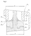
- FIG. 2 shows a detail of the differential pressure control valve according to the invention according to FIG. 1, namely the design of the valve seat (18) and the valve plate (10).
- the valve seat (18) is formed in a partition (22) of the housing (1).
- An inner edge (19) of the valve seat (18) is round.
- the outer edge (20) of the valve seat (18) has sharp edges.
- the height (H), ie the dimension between the partition (22) and the outer edge (20), is as large as possible.
- the outside diameter of the valve seat (18) is designated by the reference symbol (D) and, according to the invention, is greater than or equal to the outside diameter of the valve plate (10), which is designated by (d).
- the outer edge (21) of the valve plate (10) has the diameter (d).
- a side wall (23) of the housing (1) is as far as possible from the valve plate (10).
- Fig. 3 the same or equivalent device parts as in Figs. 1 and 2 are provided with the same reference numerals.
- the structure of the differential pressure control valve according to the invention described so far also corresponds to the structure of the differential pressure control valve according to FIG. 3.
- an additional shut-off spindle (24) can be seen, which is rotatably fastened in the spring lever (4) by an extension (27). By turning the shut-off spindle (24) it is possible to actuate the differential pressure control valve according to the invention in the closing direction.
- the differential pressure control valve according to the invention can be closed regardless of the measured pressures.
- the piston rod (8) is also opened in the direction of the central axis by means of the shut-off spindle (24) via a guide bore (31) in the piston rod (8).
- a first soft material seal which is designed as an O-ring seal (25)
- a second soft material seal which is designed as an O-ring seal (26)
- a snap ring (28) is provided in FIG. 3, which, on the other hand, is used to replace or remove and add springs of the spring set (6). can be removed. If the snap ring (28) is in the position shown in FIG. 3, it serves as a lower stop for the spring base (5).
- an upper marking (29) and a lower marking (30) are provided in FIG. 3, which serve as reading markings when the spring base (5) is rotated or adjusted in order to enable the direct reading of the to enable preset differential pressure setpoints.
- the input side pulse line connection is designated in FIG. 3 with the reference symbol (32). It is essential that the sealing of the spring cover (4) from the lower chamber (3) by means of the 0 - ring seal (26) makes it possible for the medium on the flow side to flow into the spring cover (4) via the flow line connection (32) on the flow side can, without further sealing measures between the lower chamber (3) and the piston (8) are required.
- the differential pressure control valve according to the invention now works as follows. It is assumed that the shut-off spindle (24) is in the position shown in FIG. 3 and that the differential pressure control valve is connected to the inlet, outlet and the impulse line connection on the inlet side. In this case, the differential pressure between the flow and the return is regulated by loading the diaphragm (7) in Fig. 3 above on the diaphragm (7) via the return-side impulse line (9) and via the inflow-side impulse line (32 ) the membrane (7) in Fig. 3 is loaded below. In addition, the load caused by the spring set (6) acts on the diaphragm (7) via the piston rod (8) in the same direction as the pressure on the return-side impulse line (9).
- the differential pressure control valve according to the invention has a comparatively simple mechanical structure which, owing to the selected construction, requires comparatively little sealing means in order to seal the differential pressure control valve from the environment.
- the special design of the return-side impulse line (9) means that a return-side impulse line arranged outside the valve is not necessary, so that the installation effort required for this is also eliminated.
- the special design of the valve seat (18) and valve plate (10) enables the medium to flow as freely and as quietly as possible through the differential pressure control valve according to the invention.
- the spring set (6) provided according to the invention with the adjustability via the spring base (5) enables a simple, fail-safe presetting of the desired differential pressure setpoint.
Landscapes
- Physics & Mathematics (AREA)
- Engineering & Computer Science (AREA)
- Fluid Mechanics (AREA)
- General Physics & Mathematics (AREA)
- Automation & Control Theory (AREA)
- Thermal Sciences (AREA)
- Chemical & Material Sciences (AREA)
- Combustion & Propulsion (AREA)
- Mechanical Engineering (AREA)
- General Engineering & Computer Science (AREA)
- Safety Valves (AREA)
- Details Of Valves (AREA)
Description
- Die Erfindung betrifft ein Differenzdruckregel - ventil insbesondere für Warmwasserheizungsanlagen mit einem Gehäuse, das einen Ventilsitz auf - weist, mit einer im Gehäuse verschieblich ange - ordneten Kolbenstange, die einen Ventilteller trägt, der mit dem Ventilsitz zusammenwirkt, mit einer federbelasteten und mit der Kolbenstange verbun - denen Membrane, die ventilsitzseitig über eine Rücklaufimpulsleitung mit dem Rücklaufdruck beaufschlagt wird und die auf der vom Ventilsitz abgewandten Seite über eine Vorlaufimpulsleitung mit dem Vorlaufdruck beaufschlagt wird.
- Derartige Differenzdruckregelventile werden insbesondere in Warmwasserheizungsanlagen verwendet, um eine vorgegebene Druckdifferenz zwischen dem Vorlaufdruck und dem Rücklauf - druck im Heizungskreislauf sicherzustellen.
- Es sind derartige Differenzdruckregelventile hinlänglich bekannt, bei denen die Impulsleitungen außerhalb des Ventils angeordnet sind und bei denen der Eintritt der Rücklaufimpulsleitung in das Ventil direkt am Ventilkegel angeordnet ist. Diese vorbekannten Differenzdruckregelventile haben den Nachteil, daß aufgrund der Führung der Impulslei - tung außerhalb des Ventils ein vergleichsweise hoher Installationsaufwand erforderlich ist. Der Eintritt der Rücklaufimpulsleitung direkt am Ventil - kegel führt häufig wegen der Turbulenzen in dem Bereich des Ventils zu Unstabilitäten der Regelung und Druckschwankungen in der Heizungsanlage. Die Schmutzpartikel, die häufig in dem das Ventil durchfließenden Medium schwimmen, können häufig den Eintritt der Rücklaufimpulsleitung verstopfen, weil der Mediumstrom direkt in die Ein - trittsöffnung fließt. Ist dies der Fall, so funktionieren die vorbekannten Differenzdruckregelventile nicht mehr.
- Es sind weiterhin Differenzdruckregelventile bekannt, bei denen die Federbelastung der Mem - brane durch Torsionsfedern erfolgt. Diese bekannte Art der Federbelastung hat jedoch den Nachteil, daß die Einstellung des Differenzdrucksollwertes häufig kompliziert ist. Um die Regelabweichung bei der Regelung des Differenzdruckes klein zu halten, müssen die verwendeten Federn klein sein und die Federkonstanten müssen entsprechend klein sein. Dies würde üblicherweise lange Federn erfordern. Um die Länge der Federn zu verkürzen, benutzt man häufig einen Satz von 2 oder mehr konzen - trisch liegenden Federn. Um eine Einstellung der Federkonstante und damit des gewünschten Differenzdruckes zu ermöglichen, werden häufig Fedem mit unterschiedlichen Federkonstanten verwendet. Dies hat jedoch den Nachteil, daß es beim Einbau der Federn mit verschiedenen Federkon - stanten zu Verwechslungen kommen kann, so daß möglicherweise ein falscher Differenzdrucksollwert eingestellt wird.
- Die bekannten Differenzdruckregelventile sind häufig so konstruiert, daß sie entweder nur bei großen oder nur bei kleinen Differenzdrücken im wesentlichen geräuscharm funktionieren. Dies hat den Grund, daß bei großen Druckdifferenzen die sogenannten Kavitationsgeräusche häufig störend sind und daß bei kleinen Druckdifferenzen soge - nannte Turbulenzgeräusche wie Pfeifen usw. hörbar sind. Ein Differenzdruckregelventil arbeitet jedoch praktisch oft in beiden Differenzdruckberei - chen, so daß die bekannten Differenzdruckregel - ventile entweder bei großen oder bei kleinen Druckdifferenzen Geräusche erzeugen.
- Die Erfindung hat die Aufgabe ein Differenzdruckregelventil zu schaffen, das gegenüber den Vorbekannten einfach aufgebaut ist, einen hohen Schutz gegen Verstopfung der Rücklaufimpulslei - tung bietet und wenig Installationsaufwand erfordert.
- Diese Aufgabe wird erfindungsgemäß dadurch gelöst, daß die Kolbenstange einen Aufsatz aufweist, daß die Rücklaufimpulsleitung innerhalb des Aufsatzes und der Kolbenstange angeordnet ist und daß das Gehäuse eine Tasche aufweist, in die der Aufsatz eintaucht, derart, daß der Eintritt der Rücklaufimpulsleitung sich innerhalb eines Berei - ches befindet, wo das Medium im wesentlichen ruht.
- Durch diese Maßnahmen wird ein Differenzdruckregelventil geschaffen, bei dem der Eintritt der Rücklaufimpulsleitung nicht wie beim Vorbekannten innerhalb des Bereiches der turbulenten Strömung des durch das Differenzdruckregelventil gesteuerten Mediums sich befindet. Das durch das Differenzdruckregelventil gesteuerte Medium fließt im wesentlichen an dem Aufsatz vorbei und das in der erfindungsgemäß vorgesehenen Tasche des Gehäuses befindliche Medium ruht im wesentli - chen. In dieser Tasche ist das Ende des Aufsatzes angeordnet, in dem der Eintritt der Rücklaufim - pulsleitung vorgesehen ist.
- Dadurch, daß die Rücklaufimpulsleitung innerhalb des Aufsatzes und der Kolbenstange ange - ordnet ist, sind zur Druckbeaufschlagung der Membrane mit dem Rücklaufdruck keinerlei zu - sätzliche und zusätzlich zu installierende Leitungen erforderlich, so daß gegenüber dem Vorbekannten der Installationsaufwand verringert ist und die Ge - fahr der Beschädigung einer solchen freistehenden Rücklaufimpulsleitung vermieden wird.
- Durch das Fehlen einer zusätzlich erforderli - chen Rücklaufimpulsleitung ist das erfindungsgemäße Differenzdruckregelventil wesentlich einfacher und kostengünstiger herstellbar als die vorbekannten Differenzdruckregelventile.
- Durch die Anordnung der Eintrittsöffnung der Rücklaufimpulsleitung außerhalb des turbulenten Strömungsbereiches des zu steuernden Mediums ist die Verschmutzungsgefahr der Eintrittsöffnung und damit der Rücklaufimpulsleitung gegenüber dem Vorbekannten wesentlich verringert.
- Vorteilhafte Ausgestaltungen und Weiterbildungen des erfindungsgemäßen Differenzdruckregelventils gehen aus den Unteransprüchen hervor.
- Es ist besonders vorteilhaft, wie in Anspruch 2 beansprucht, den Eintritt in die Rücklaufimpulslei - tung an dem dem Boden der Tasche zugewandten oberen Rand des Aufsatzes anzuordnen, weil durch diese Maßnahme der Eintritt in die Rücklaufimpulsleitung möglichst weit weg von dem Bereich der turbulenten Strömung des zu steuernden Mediums erfolgt und damit die Verschmutzung der Rücklaufimpulsleitung soweit wie möglich ausgeschlossen wird. Es ist weiterhin besonders vorteil - haft, wenn eine vorlaufseitige Kante einer Gehäu - sewand des Gehäuses etwas schräg zur Achse des Aufsatzes besteht und in Richtung zum Ven - tilteller geneigt ist, weil durch diese Maßnahme eine Strömungsleitung im wesentlichen weg von der Tasche des Gehäuses und damit weg vom Eintritt in die Rücklaufimpulsleitung des zu steu - ernden Mediums erfolgt. Dies trägt zu einer wei - teren Beruhigung der Strömung in der Tasche des Gehäuses bei.
- Es ist weiterhin besonders vorteilhaft, wenn gemäß Anspruch 3 die Tiefe der Tasche und die Länge des Aufsatzes derart bemessen sind, daß auch bei vollgeöffnetem Differenzdruckregelventil und damit vollabgehobenem Ventilteller vom Ven - tilsitz der Eintritt in die Impulsleitung sich in der Tasche befindet, weil durch diese Maßnahme auch bei vollgeöffnetem Differnzdruckregelventil sichergestellt ist, daß der Eintritt in die Impulsleitung außerhalb des turbulenten Strömungsbereiches sich befindet.
- Man kann die Rücklaufimpulsleitung gemäß Anspruch 4 vorteilhaft in eine einstückig ausgebil - dete Oberkammer münden lassen, die direkt in das Gehäuse eingeschraubt ist und eine Unterkammer vorsehen, wobei die Membrane abgedichtet zwi - schen Oberkammer und Unterkammer eingespannt ist. Durch diese Maßnahmen wird der konstruktive Aufbau des erfindungsgemäßen Differenzdruckregelventils wesentlich vereinfacht.
- Es ist besonders vorteilhaft, wenn gemäß An - spruch 5 die Membrane durch einen Federsatz bestehend aus einer oder mehreren Schraubenfe - dem in Öffnungsrichtung des Differenzdruckregel - ventils belastet ist und wenn die Schraubenfedern alle die gleiche Länge und die gleiche Federkon - stante aufweisen. Durch diese Maßnahmen kann eine Solldruckdifferenz durch Wahl der Anzahl der Schraubenfedern einfach vorgegeben werden, wobei aufgrund der Tatsache, daß die Schraubenfe - dem alle die gleiche Länge und die gleiche Federkonstante aufweisen, es egal ist, welche der vorhandenen Schraubenfedern man für den Federsatz im Einzelfall verwendet.
- Zur Vereinfachung der mechanischen Konstruktion des erfindungsgemäßen Differenzdruckregelventils kann in diesem Zusammenhang vorteilhaft gemäß Anspruch 6 der Federsatz sich ei - nerseits an der Unterkammer unmittelbar abstützen. Andererseits kann der Federsatz durch eine an der Kolbenstange angeordnete verstellbare Fe - derbasis in seiner Vorspannung veränderlich sein. Durch diese Maßnahmen ist es einfach möglich, die durch die Wahl der Zahl der Schraubenfedern vorgegebene Solldruckdifferenz durch Verstellung der Federbasis und damit durch Veränderung der Federvorspannung auf verschiedene Werte einzu - stellen.
- Zum Schutz des genannten Federsatzes kann vorteilhaft gemäß Anspruch 7 eine abnehmbare Federhaube vorgesehen sein, die den Federsatz umschließt und die an der Unterkammer angeord - net ist. Durch diese Maßnahmen kann eine Beschädigung des Federsatzes vermieden werden. Andererseits ist es möglich das erfindungsgemäße Differenzdruckregelventil einfach konstruktiv aus - zugestalten, weil der den Federsatz umschließende Federhaubenteil z. B. durch das zu steuernde Me - dium durchspült werden kann. In diesen Zusam - menhang ist es vorteilhaft, wenn eine Absperrspindel vorgesehen ist, die durch einem Ansatz in der Federhaube drehbar gelagert ist und die in einer Führungsbohrung der Kolbenstange dreh - und verschiebbar gelagert ist. Mit Hilfe dieser Ab - sperrspindel ist eine Absperrung des Differenzdruckregelventils möglich z. B. für die Durchfüh - rung von Wartungs - und Instandsetzungsarbeiten an einer Warmwasserheizungsanlage. Durch die drehbare Lagerung der Absperrspindel in der Fe - derhaube mittels des genannten Ansatzes ist die Absperrspindel unverlierbar und kann z. B. nicht aus der Federhaube herausgedreht werden. Durch die dreh - und verschiebbare Lagerung der Ab - sperrspindel in einer Führungsbohrung der Kol - benstange kann auf eine weitere Führung der Kol - benstange in dem Gehäuse der Oberkammer oder der Unterkammer verzichtet werden, was die me - chanische Konstruktion des erfindungsgemäßen Differenzdruckregelventils wesentlich verbessert und vereinfacht.
- Es ist weiterhin vorteilhaft, wenn gemäß An - spruch 8 die Federbasis durch einen Sprengring gegen Abdrehen oder Abfallen gesichert ist und wenn die Kolbenstange Markierungen, insbeson - dere Markierungsnuten, für die Einstellung der Federbasis aufweist. Durch den Sprengring bzw. die Markierungen ist es möglich, die Feineinstel - lung der Federvorspannung und damit die Fein - einstellung des Solldifferenzdruckes durch Verstellung der Federbasis unmittelbar abzulesen.
- Um gegebenenfalls die Abdichtung des erfin - dungsgemäßen Differenzdruckregelventils gegen - über der Umgebung zu verbessern, kann es gemäß Anspruch 9 vorteilhaft sein zwischen der Oberkammer und dem Gehäuse und/oder zwischen der Unterkammer und der Federhaube eine Weichstoffdichtung, insbesondere eine 0 - Ring - dichtung vorzusehen.
- Schließlich ist es besonders vorteilhaft, gemäß Anspruch 10 den Durchmesser des Ventiltellers gleich oder derart kleiner als den Durchmesser des Ventilsitzes zu wählen, daß auch bei größter ferti - gungsbedingter Abweichung der äußere Rand des Ventiltellers nicht über den äußeren Rand des Ventilsitzes hinausragt. In diesem Zusammenhang kann der äußere Rand des Ventilsitzes scharfkantig sein und von der Trennwand und der Seitenwand des Gehäuses möglichst weit entfernt sein. Der innere Rand des Ventilsitzes kann abgerundet sein und der äußere Rand des Ventiltellers kann scharfkantig sein. Durch diese Maßnahmen ist eine deutliche Geräuschreduzierung des erfindungsge - mäßen Differenzdruckregelventils möglich, weil das durch das Differenzdruckregelventil gesteuerte Medium so frei wie möglich an der Engstelle zwi - schen dem Ventilteller und dem Ventilsitz vorbeis - trömen kann, ohne daß es zu übermäßigen Turbulenzen oder zu Kavitation kommt.
- Ausführungsbeispiele des erfindungsgemäßen Differenzdruckregelventils sind in den Zeichnungen dargestellt und werden im Folgenden anhand der Zeichnungen näher erläutert.
- Es zeigen
- Fig. 1 ein erfindungsgemäßes Differenzdruckregelventil in einem Schnitt durch die Mittelachse
- Fig. 2 ein Detail des erfindungsgemäßen Differenzdruckregelventils gemäß Fig. 1 betreffend die Ausgestaltung von Ventilteller und Ventilsitz und
- Fig. 3 ein zweites Ausführungsbeispiel eines erfindungsgemäßen Differenzdruck - regelventils.
- Das Differenzdruckregelventil gemäß Fig. 1 besteht aus einem Gehäuse (1), einer Oberkammer (2), einer Unterkammer (3) und einem Deckel bzw. einer Federhaube (4). Im Inneren des erfindungs - gemäßen Differenzdruckregelventils sind eine Konsole oder Federbasis (5), ein Federsatz (6), eine Membrane (7) und eine Kolbenstange (8) mit im Inneren angeordneter Rücklaufimpulsleitung (9) vorgesehen.
- An der Kolbenstange (8) ist ein Ventilteller (10) und ein Aufsatz (11) angeordnet. Ein Eintritt (14) in die Impulsleitung (9) ist im oberen Rand (17) des Aufsatzes (11) angeordnet. Im Gehäuse (1) ist in der Wand (12) eine Tasche (16) vorgesehen. Die Tasche (16) erstreckt sich vom vorlaufseitigen Rand (13) bis zum rücklaufseitigen Rand (15) der Wand (12). Das durch das Differenzdruckregelventil zu steuernde Medium tritt aus der Richtung (A), die die Eingangsseite kennzeichnet, in das Gehäuse (1) ein, fließt über den Ventilteller (10) und verläßt in Richtung (B) zur Ausgangsseite hin das Gehäu - se (1). Der ausgangsseitige Druck des zu steuern - den Mediums wirkt über die Impulsleitung (9) auf die in der Fig. 1 obere Seite der Membrane (7). Auf die andere untere Seite der Membrane (7) wirkt der Druck des Eingangs vor dem Gehäuse (1) des erfindungsgemäßen Differenzdruckregelventils. Der Federsatz (6) wirkt auf die Kolbenstange (8) in gleicher Richtung wie der Druck auf der oberen Seite der Membrane (7).
- In der Fig. 1 ist das erfindungsgemäße Diffe - renzdruckregelventil rechts in der geschlossenen Stellung und links in der vollgeöffneten Stellung dargestellt. Man erkennt, daß der obere Rand (17) des Aufsatzes (11) sowohl in der geschlossenen als auch in der vollgeöffneten Stellung des Diffe - renzdruckregelventils immer in der Tasche (16) sich befindet. D. h. der obere Rand (17) ist immer höher als der Rand (13) in der Wand (12). D. h. der Eintritt (14) der Impulsleitung (9) liegt immer geschützt in der Tasche (16) und von der Strömung des Mediums im Gehäuse (1) entfernt. Das Medi - um z. B. das Wasser einer Warmwasserheizungs - anlage fließt parallel zur Wand (12) vorbei am Rand (13). Durch diese erfindungsgemäßen Maßnahmen ist eine Möglichkeit der Verschmutzung der Irnpulsleitung (9) durch im Medium befindliche Parti - kel gegenüber dem Vorbekannten wesentlich geringer. Der Eintritt (14) der Impulsleitung (9) ist weit entfernt vom Ventilteller (10) und die dort auftre - tenden Turbulenzen und Druckschwankungen beeinflußen den von der Impulsleitung (9) übermittelten Druck nicht, so daß die Regelung des Diffe - renzdruckes bei dem erfindungsgemäßen Differenzdruckregelventil gegenüber dem Vorbekannten stabiler ist.
- Der Federsatz (6) besteht bei dem erfindungsgemäßen Differenzdruckregelventil gemäß Fig. 1 aus einer zwei - oder mehrkonzentrisch lie - genden Torsions - oder Schraubenfeder. Wesentlich ist in diesem Zusammenhang, daß alle Federn die gleiche Länge und die gleiche Federkonstante aufweisen. Allein der Durchmesser der Torsions-und Schraubenfedern ist unterschiedlich. Durch diese Maßnahme wird sichergestellt, daß alle verwendeten Federn bei gleicher Vorspannung die gleiche Kraft ausüben. Der Austausch der Federn des Federsatzes (6) ist möglich, wenn man den Deckel oder die Federhaube (4) und die Federbasis oder Konsole (5) entfernt.
- In Fig. 2 sind gleiche oder gleichwirkende Vorrichtungsteile wie in Fig. 1 mit den gleichen Bezugszeichen versehen. In der Fig. 2 ist ein Detail des erfindungsgemäßen Differenzdruckregelventils gemäß Fig. 1 dargestellt, nämlich die Ausbildung des Ventilsitzes (18) und des Ventiltellers (10). In einer Trennwand (22) des Gehäuses (1) ist der Ventilsitz (18) ausgebildet. Ein innerer Rand (19) des Ventilsitzes (18) ist rund ausgebildet. Der äu - ßere Rand (20) des Ventilsitzes (18) ist jedoch scharfkantig. Die Höhe (H), also das Maß zwischen der Trennwand (22) und dem äußeren Rand (20), ist möglichst groß. Der Außendurchmesser des Ventilsitzes (18) ist mit dem Bezugszeichen (D) bezeichnet und ist erfindungsgemäß größer oder gleich dem Außendurchmesser des Ventiltellers (10), der mit (d) bezeichnet ist. Hierbei hat der äußere Rand (21) des Ventiltellers (10) den Durchmesser (d). Eine Seitenwand (23) des Gehäuses (1) ist so weit wie möglich entfernt vom Ventilteller (10). Durch die beschriebenen Maßnahmen wird sichergestellt, daß das vom erfin - dungsgemäßen Differenzdruckregelventil gesteuerte Medium beim Öffnen des Ventils, d. h. beim Abheben des Ventiltellers (10) vom Ventilsitz (18), möglichst frei und unbehindert und ohne Erzeu - gung von Turbulenzen durch die Engstelle zwi - schen dem Ventilteller (10) und dem Ventilsitz (18) strömen kann, so daß möglichst wenig Turbulen - zen oder Kavitation auftreten. In diesem Zusammenhang ist besonders wichtig, daß der Durch - messer (D) des Ventilsitzes (18) größer oder gleich dem Durchmesser (d) des Ventiltellers (10) ist.
- In Fig. 3 sind gleiche oder gleichwirkende Vorrichtungsteile, wie in den Fig. 1 und 2, mit den gleichen Bezugszeichen versehen. Der bisher beschriebene Aufbau des erfindungsgemäßen Differenzdruckregelventils entspricht auch dem Aufbau des Differenzdruckregelventils gemäß Fig. 3. In Fig. 3 erkennt man zusätzlich eine Absperrspindel (24), die durch einen Ansatz (27) in der Federhau - be (4) drehbar befestigt ist. Durch Drehung der Absperrspindel (24) ist eine Betätigung des erfin - dungsgemäßen Differenzdruckregelventils in Schließrichtung möglich, so daß z. B. für Wartungsarbeiten an einer Warmwasserheizungsanlage das erfindungsgemäße Differenzdruckregelventil unabhängig von den gemessenen Drücken geschlossen werden kann. Über eine Führungsbohrung (31) in der Kolbenstange (8) wird mittels der Absperrspindel (24) auch die Kolbenstange (8) in Richtung der Mittelachse geöffnet. Durch diese Maßnahme ist keine weitere Führung der Kolben - stange (8) in der Unterkammer (3) des erfindungsgemäßen Differenzdruckregelventils erforderlich. Zur möglichst sicheren Abdichtung der Oberkammer (2) gegenüber dem Gehäuse (1) und der Unterkammer (3) gegenüber dem Deckel bzw. der Federhaube (4) sind in Fig. 3 eine erste Weichstoffdichtung, die als O-Ringdichtung (25) ausgebildet ist und eine zweite Weichstoffdichtung, die als O-Ringabdichtung (26) ausgebildet ist, vorgesehen.
- Um ein ungewolltes Abdrehen der Federbasis (5) von dem Gewinde der Kolbenstange (8) zu verhindern, ist in der Fig. 3 ein Sprengring (28) vorgesehen, der andererseits zum Auswechseln bzw. zum Entnehmen und Zufügen von Federn des Federsatzes (6) entnommen werden kann. Befindet sich der Sprengring (28) in der in Fig. 3 dargestellten Position, so dient er als unterer Anschlag für die Federbasis (5). Weiterhin sind in Fig. 3 eine obere Markierung (29) und eine untere Markierung (30) vorgesehen, die bei einer Verdrehung bzw. Verstellung der Federbasis (5) als Ablesemarkie - rung dienen, um bei einer Feineinstellung des voreingestellten Differenzsolldruckes die direkte Ablesung der voreingestellten Differenzdrucksoll - werte zu ermöglichen.
- Schließlich ist in Fig. 3 mit dem Bezugszeichen (32) der eingangsseitige Impulsleitungsanschluß bezeichnet. Wesentlich ist, daß durch die Abdich - tung der Federhaube (4) gegenüber der Unterkammer (3) mittels der 0 - Ringdichtung (26) es möglich ist, daß das vorlaufseitige Medium über den vorlaufseitigen Impulsleitungsanschluß (32) in die Federhaube (4) hineinströmen kann, ohne daß weitere Abdichtungsmaßnahmen zwischen der Unterkammer (3) und dem Kolben (8) erforderlich sind.
- Das erfindungsgemäße Differenzdruckregel - ventil funktioniert nun folgendermaßen. Es sei an - genommen, daß sich die Absperrspindel (24) in der in Fig. 3 dargestellten Stellung befindet und daß das Differenzdruckregelventil mit Eingang, Ausgang und dem eingangsseitigen Impulsleitungsanschluß verbunden ist. In diesem Falle wird der Differenz - druck zwischen dem Vorlauf und dem Rücklauf dadurch geregelt, daß auf die Membrane (7) über die rücklaufseitige Impulsleitung (9) die Membrane (7) in Fig. 3 oben belastet ist und über die vorlaufseitige Impulsleitung (32) die Membrane (7) in Fig. 3 unten belastet ist. Zusätzlich wirkt die Belastung durch den Federsatz (6) auf die Membrane (7) über die Kolbenstange (8) in der gleichen Richtung wie der Druck über die rücklaufseitige Impulsleitung (9). Durch die wirkenden Drücke und durch die wirkenden Federkräfte stellt sich eine bestimmte Lage des Ventiltellers (10) gegenüber dem Ventilsitz (18) ein, die sich abhängig von den Drücken in Vorlauf und Rücklauf ändert. Soll nun das erfindungsgemäße Differenzdruckregelventil zu Wartungszwecken geschlossen werden, so wird die Absperrspindel (24) in Fig. 3 nach oben in die Federhaube (4) hineingedreht, so daß die Kolben - stange (8) in Fig. 3 nach oben geschoben wird, bis der Ventilteller (10) auf dem Ventilsitz (18) aufliegt.
- Wie insbesondere der Fig. 3 zu entnehmen ist, weist das erfindungsgemäße Differenzdruckregel - ventil einen vergleichsweise einfachen mechani - schen Aufbau auf, der aufgrund der gewählten Konstruktion vergleichsweise wenig Dichtmittel erfordert, um das Differenzdruckregelventil gegen - über der Umgebung abzudichten. Weiterhin ist durch die besondere Konstruktion der rücklaufsei - tigen Impulsleitung (9) eine außerhalb des Ventils angeordnete rücklaufseitige Impulsleitung nicht erforderlich, so daß auch der dafür gegebenenfalls erforderliche Installationsaufwand entfällt. Durch die besondere Ausbildung von Ventilsitz (18) und Ventilteller (10) wird eine möglichst freie und geräuscharme Strömung des Mediums durch das erfindungsgemäße Differenzdruckregelventil ermöglicht. Durch den erfindungsgemäß vorgesehe - nen Federsatz (6) mit der Verstellbarkeit über die Federbasis (5) ist eine einfache, störungssichere Voreinstellung des gewünschten Differenzdrucksollwertes möglich.
Claims (10)
Priority Applications (1)
| Application Number | Priority Date | Filing Date | Title |
|---|---|---|---|
| AT89113952T ATE89899T1 (de) | 1988-08-11 | 1989-07-28 | Differenzdruckregelventil. |
Applications Claiming Priority (4)
| Application Number | Priority Date | Filing Date | Title |
|---|---|---|---|
| YU1553/88 | 1988-08-11 | ||
| YU155388A YU155388A (en) | 1988-08-11 | 1988-08-11 | Stable effecting spring controlling valve |
| YU88/89 | 1989-01-16 | ||
| YU8889 | 1989-01-16 |
Publications (4)
| Publication Number | Publication Date |
|---|---|
| EP0354427A2 EP0354427A2 (de) | 1990-02-14 |
| EP0354427A3 EP0354427A3 (de) | 1991-01-02 |
| EP0354427B1 true EP0354427B1 (de) | 1993-05-26 |
| EP0354427B2 EP0354427B2 (de) | 1998-09-16 |
Family
ID=27130709
Family Applications (1)
| Application Number | Title | Priority Date | Filing Date |
|---|---|---|---|
| EP89113952A Expired - Lifetime EP0354427B2 (de) | 1988-08-11 | 1989-07-28 | Differenzdruckregelventil |
Country Status (2)
| Country | Link |
|---|---|
| EP (1) | EP0354427B2 (de) |
| DE (1) | DE58904471D1 (de) |
Families Citing this family (16)
| Publication number | Priority date | Publication date | Assignee | Title |
|---|---|---|---|---|
| ATE101907T1 (de) * | 1989-06-26 | 1994-03-15 | Milan Medvescek | Membrangesteuertes differenzdruck-regelventil. |
| DE4131709C1 (en) * | 1991-09-24 | 1992-12-10 | Danfoss A/S, Nordborg, Dk | Fluid pressure differential controlled valve - has housing with seat and valve rod seal with diaphragm |
| US5443083A (en) * | 1993-02-11 | 1995-08-22 | Itt Corporation | Pressure-reducing regulator for compressed natural gas |
| US5285810A (en) * | 1993-02-11 | 1994-02-15 | Itt Corporation | Pressure-reducing regulator for compressed natural gas |
| DE4445589C2 (de) * | 1994-12-20 | 1997-12-18 | Danfoss As | Membrangesteuertes Ventil zur Aufrechterhaltung eines Differenzdrucks |
| DE4445588C2 (de) * | 1994-12-20 | 2002-12-05 | Danfoss As | Membrangesteuertes Differenzdruckventil |
| CA2312122A1 (en) | 2000-06-23 | 2001-12-23 | Erick Girouard | Gas flow regulation system |
| CA2312237A1 (en) | 2000-06-23 | 2001-12-23 | Erick Girouard | Pressure regulator |
| DE102006005411A1 (de) * | 2006-01-30 | 2007-08-09 | Danfoss A/S | Ventil |
| LU91787B1 (en) * | 2011-02-04 | 2012-08-06 | Luxembourg Patent Co | Gas pressure reducer with disk spring |
| PL3462067T3 (pl) * | 2013-09-11 | 2021-06-14 | Danfoss A/S | Różnicowy zawór ciśnieniowy |
| CN109442072A (zh) * | 2018-12-08 | 2019-03-08 | 河北金桥平衡阀门有限公司 | 一种自力式压差控制阀 |
| CN112923086B (zh) * | 2019-12-05 | 2022-10-04 | 中国石油天然气股份有限公司 | 调压阀及管道传输系统 |
| CN110822145B (zh) * | 2019-12-16 | 2024-09-17 | 南通市中龙液压有限公司 | 一种定差压力补偿阀 |
| CN111577904B (zh) * | 2020-05-28 | 2025-01-28 | 内蒙古鑫广进燃气设备有限责任公司 | 一种补偿弹簧效应的直接作用式调压器 |
| CN113217643A (zh) * | 2021-06-02 | 2021-08-06 | 中国长江三峡集团有限公司 | 差压式爆管安全阀及方法 |
Family Cites Families (4)
| Publication number | Priority date | Publication date | Assignee | Title |
|---|---|---|---|---|
| GB590947A (en) * | 1944-12-28 | 1947-08-01 | Leopold Friedman | Improvements in and relating to fluid pressure governors |
| FR566512A (fr) * | 1922-06-09 | 1924-02-15 | Arca Regulatorer Ab | Dispositif pour le nettoyage automatique de passages ou de conduits étroits traversés par des liquides |
| US2377227A (en) * | 1941-06-04 | 1945-05-29 | Donald G Griswold | Pressure responsive valve |
| US3570529A (en) * | 1969-10-13 | 1971-03-16 | Gen Signal Corp | Emergency vent valve |
-
1989
- 1989-07-28 EP EP89113952A patent/EP0354427B2/de not_active Expired - Lifetime
- 1989-07-28 DE DE8989113952T patent/DE58904471D1/de not_active Expired - Fee Related
Also Published As
| Publication number | Publication date |
|---|---|
| EP0354427B2 (de) | 1998-09-16 |
| EP0354427A3 (de) | 1991-01-02 |
| EP0354427A2 (de) | 1990-02-14 |
| DE58904471D1 (de) | 1993-07-01 |
Similar Documents
| Publication | Publication Date | Title |
|---|---|---|
| EP0354427B1 (de) | Differenzdruckregelventil | |
| DE60117219T2 (de) | Elektromagnetisches Ventil | |
| EP0751448B1 (de) | Durchfluss-Regelventil | |
| EP2271969B1 (de) | Armaturenkombination zur regelung der durchflussmenge oder des differenzdruckes | |
| EP3104246A1 (de) | Durchflussregelventil | |
| WO2001079951A1 (de) | Gasdruckregler | |
| EP0911715A1 (de) | Durchfluss-Regelventil mit integriertem Druckregler | |
| DE69908588T2 (de) | Umschlossene positionsanzeige für schieber eines kontrollventils | |
| EP0119503B1 (de) | Temperaturabhängig steuerbares Heizungsventil mit Voreinstellvorrichtung | |
| DE3625428A1 (de) | Proportional-drosselventil | |
| DE102013107762A1 (de) | Durchflussregelventil | |
| DE4445588C2 (de) | Membrangesteuertes Differenzdruckventil | |
| EP0630452B1 (de) | Proportional-wegeventil | |
| DE2527249C2 (de) | Druckregler für strömende Medien | |
| DE4019757A1 (de) | Membrangesteuerter gasdruckregler | |
| DE3741676A1 (de) | Durchflussregelventil | |
| DE4416154A1 (de) | Durchflußregelventil | |
| CH660512A5 (en) | Hydraulic control element | |
| DE102007013505A1 (de) | Armaturenkombination zur Regelung der Durchflussmenge oder des Differenzdruckes | |
| DE4407447A1 (de) | Voreinstellbares Regulierventil | |
| DE2032859A1 (de) | Druckregelventil | |
| DE202004003811U1 (de) | Volumenstromregler | |
| EP0071066B1 (de) | Mengenregulierventil | |
| EP0216982B1 (de) | Federbelastetes Sicherheitsventil | |
| DE4328617A1 (de) | Stellgerät mit Hilfssteuerung |
Legal Events
| Date | Code | Title | Description |
|---|---|---|---|
| PUAI | Public reference made under article 153(3) epc to a published international application that has entered the european phase |
Free format text: ORIGINAL CODE: 0009012 |
|
| AK | Designated contracting states |
Kind code of ref document: A2 Designated state(s): AT BE CH DE FR LI NL |
|
| PUAL | Search report despatched |
Free format text: ORIGINAL CODE: 0009013 |
|
| AK | Designated contracting states |
Kind code of ref document: A3 Designated state(s): AT BE CH DE FR LI NL |
|
| 17P | Request for examination filed |
Effective date: 19901221 |
|
| 17Q | First examination report despatched |
Effective date: 19920514 |
|
| GRAA | (expected) grant |
Free format text: ORIGINAL CODE: 0009210 |
|
| AK | Designated contracting states |
Kind code of ref document: B1 Designated state(s): AT BE CH DE FR LI NL |
|
| REF | Corresponds to: |
Ref document number: 89899 Country of ref document: AT Date of ref document: 19930615 Kind code of ref document: T |
|
| REF | Corresponds to: |
Ref document number: 58904471 Country of ref document: DE Date of ref document: 19930701 |
|
| ET | Fr: translation filed | ||
| PLBI | Opposition filed |
Free format text: ORIGINAL CODE: 0009260 |
|
| 26 | Opposition filed |
Opponent name: DANFOSS A/S Effective date: 19940212 |
|
| NLR1 | Nl: opposition has been filed with the epo |
Opponent name: DANFOSS A/S |
|
| APAC | Appeal dossier modified |
Free format text: ORIGINAL CODE: EPIDOS NOAPO |
|
| PLAW | Interlocutory decision in opposition |
Free format text: ORIGINAL CODE: EPIDOS IDOP |
|
| PUAH | Patent maintained in amended form |
Free format text: ORIGINAL CODE: 0009272 |
|
| STAA | Information on the status of an ep patent application or granted ep patent |
Free format text: STATUS: PATENT MAINTAINED AS AMENDED |
|
| 27A | Patent maintained in amended form |
Effective date: 19980916 |
|
| AK | Designated contracting states |
Kind code of ref document: B2 Designated state(s): AT BE CH DE FR LI NL |
|
| REG | Reference to a national code |
Ref country code: CH Ref legal event code: AEN Free format text: AUFRECHTERHALTUNG DES PATENTES IN GEAENDERTER FORM |
|
| NLR2 | Nl: decision of opposition | ||
| NLR3 | Nl: receipt of modified translations in the netherlands language after an opposition procedure | ||
| ET3 | Fr: translation filed ** decision concerning opposition | ||
| PGFP | Annual fee paid to national office [announced via postgrant information from national office to epo] |
Ref country code: DE Payment date: 20000726 Year of fee payment: 12 |
|
| PGFP | Annual fee paid to national office [announced via postgrant information from national office to epo] |
Ref country code: FR Payment date: 20010518 Year of fee payment: 13 |
|
| PGFP | Annual fee paid to national office [announced via postgrant information from national office to epo] |
Ref country code: BE Payment date: 20010629 Year of fee payment: 13 |
|
| PGFP | Annual fee paid to national office [announced via postgrant information from national office to epo] |
Ref country code: AT Payment date: 20010726 Year of fee payment: 13 |
|
| PGFP | Annual fee paid to national office [announced via postgrant information from national office to epo] |
Ref country code: NL Payment date: 20010731 Year of fee payment: 13 |
|
| PGFP | Annual fee paid to national office [announced via postgrant information from national office to epo] |
Ref country code: CH Payment date: 20011031 Year of fee payment: 13 |
|
| PG25 | Lapsed in a contracting state [announced via postgrant information from national office to epo] |
Ref country code: DE Free format text: LAPSE BECAUSE OF NON-PAYMENT OF DUE FEES Effective date: 20020401 |
|
| PG25 | Lapsed in a contracting state [announced via postgrant information from national office to epo] |
Ref country code: AT Free format text: LAPSE BECAUSE OF NON-PAYMENT OF DUE FEES Effective date: 20020728 |
|
| PG25 | Lapsed in a contracting state [announced via postgrant information from national office to epo] |
Ref country code: LI Free format text: LAPSE BECAUSE OF NON-PAYMENT OF DUE FEES Effective date: 20020731 Ref country code: CH Free format text: LAPSE BECAUSE OF NON-PAYMENT OF DUE FEES Effective date: 20020731 Ref country code: BE Free format text: LAPSE BECAUSE OF NON-PAYMENT OF DUE FEES Effective date: 20020731 |
|
| BERE | Be: lapsed |
Owner name: *MEDVESCEK MILAN Effective date: 20020731 |
|
| PG25 | Lapsed in a contracting state [announced via postgrant information from national office to epo] |
Ref country code: NL Free format text: LAPSE BECAUSE OF NON-PAYMENT OF DUE FEES Effective date: 20030201 |
|
| REG | Reference to a national code |
Ref country code: CH Ref legal event code: PL |
|
| PG25 | Lapsed in a contracting state [announced via postgrant information from national office to epo] |
Ref country code: FR Free format text: LAPSE BECAUSE OF NON-PAYMENT OF DUE FEES Effective date: 20030331 |
|
| NLV4 | Nl: lapsed or anulled due to non-payment of the annual fee |
Effective date: 20030201 |
|
| REG | Reference to a national code |
Ref country code: FR Ref legal event code: ST |
|
| APAH | Appeal reference modified |
Free format text: ORIGINAL CODE: EPIDOSCREFNO |