EP0354030B1 - Entwicklungssystem - Google Patents
Entwicklungssystem Download PDFInfo
- Publication number
- EP0354030B1 EP0354030B1 EP89307892A EP89307892A EP0354030B1 EP 0354030 B1 EP0354030 B1 EP 0354030B1 EP 89307892 A EP89307892 A EP 89307892A EP 89307892 A EP89307892 A EP 89307892A EP 0354030 B1 EP0354030 B1 EP 0354030B1
- Authority
- EP
- European Patent Office
- Prior art keywords
- housing
- chamber
- exit port
- developer material
- toner particles
- Prior art date
- Legal status (The legal status is an assumption and is not a legal conclusion. Google has not performed a legal analysis and makes no representation as to the accuracy of the status listed.)
- Expired - Lifetime
Links
Images

Classifications
-
- G—PHYSICS
- G03—PHOTOGRAPHY; CINEMATOGRAPHY; ANALOGOUS TECHNIQUES USING WAVES OTHER THAN OPTICAL WAVES; ELECTROGRAPHY; HOLOGRAPHY
- G03G—ELECTROGRAPHY; ELECTROPHOTOGRAPHY; MAGNETOGRAPHY
- G03G15/00—Apparatus for electrographic processes using a charge pattern
- G03G15/06—Apparatus for electrographic processes using a charge pattern for developing
- G03G15/08—Apparatus for electrographic processes using a charge pattern for developing using a solid developer, e.g. powder developer
- G03G15/0822—Arrangements for preparing, mixing, supplying or dispensing developer
- G03G15/0844—Arrangements for purging used developer from the developing unit
-
- G—PHYSICS
- G03—PHOTOGRAPHY; CINEMATOGRAPHY; ANALOGOUS TECHNIQUES USING WAVES OTHER THAN OPTICAL WAVES; ELECTROGRAPHY; HOLOGRAPHY
- G03G—ELECTROGRAPHY; ELECTROPHOTOGRAPHY; MAGNETOGRAPHY
- G03G13/00—Electrographic processes using a charge pattern
- G03G13/06—Developing
- G03G13/08—Developing using a solid developer, e.g. powder developer
- G03G13/09—Developing using a solid developer, e.g. powder developer using magnetic brush
Definitions
- This invention relates generally to an electrophotographic printing machine, and more particularly concerns an apparatus for developing an electrostatic latent image used in a printing machine, including: means for transporting a developer material comprising at least carrier granules having toner particles adhering thereto into contact with the electrostatic latent image; a housing defining a chamber having a supply of developer material therein, said transporting means being in communication with the chamber of said housing for receiving developer material, said housing having an exit port for removing developer material from the chamber thereof when the quantity of developer material therein is greater than a predetermined quantity; and means for discharging toner particles and carrier granules into the chamber of said housing.
- a photoconductive member In the process of electrophotographic printing, a photoconductive member is uniformly changed and exposed to a light image of an original document. Exposure of the photoconductive member records an electrostatic latent image corresponding to the informational areas contained within the original document. After the electrostatic latent image is recorded on the photoconductive surface, the latent image is developed by bringing a developer material into contact therewith. This forms a power image on the photoconductive member which is subsequently transferred to a copy sheet and permanently affixed thereto in image configuration.
- the developer material comprises toner particules adhering triboelectrically to magnetic carrier granules. This two component mixture is brought into contact with the photoconductive surface. The toner particles are attracted from the carrier granules to the latent image. It is clear that the developer material is a critical component of the printing machine. As the developer material ages and approaches the end of its useful life, copy quality deteriorates. It has been found that by adding addition carrier granules, the life of the developer material can be significantly increased. However, as additional carrier granules are added to the chamber storing the developer material, developer material must be removed therefrom to maintain the developer material therein at the desired quantity.
- airborne toner particles escape through the exit port as well as developer material and denuded carrier granules, i.e. carrier granules without toner particles adhering thereto.
- the airborne toner particles contaminate the various other subsystems within the printing machine reducing their life and causing copy quality problems.
- Various approaches have been devised to achieve the foregoing.
- US-A-4,387,982 discloses a removable charged particle containment apparatus which is electrically biased to a voltage level different than that of the image voltage recorded on the photoconductive member to repel or attract the charged particles therefrom.
- US-A-4,394,086 describes a particle containment apparatus for an electrophotographic printing machine which controls air flowing into and out of a chamber in a housing to minimize the escape of particles therefrom.
- US-A-4,614,165 discloses a development apparatus wherein additional carrier granules are continually added to developer material in the chamber of the developer housing.
- An exit port is provided to remove the excess developer material so as to maintain the developer material at a predetermined quantity.
- US-A-4,697,914 describes a toner containment method and apparatus which creates an electric field barrier in the exit portion of the housing in an electrostatic reproducing machine sufficient to repel the charged particles in the exiting air back into the principal portion of the housing without restricting the air flow from the exit portion.
- EP-A-0,221,281 describes a development apparatus in which the developer station is provided with a magnetic closing device in the vicinity of its discharge opening.
- the magnetic closing device functions such that in its energized condition, a magnetic field acts on the developer mix to form a plug of developer mix closing off the discharge opening. In the de-energized condition, the magnetic closing device releases the discharge opening whereupon the developing station is emptied by the action of a suction device such as a blower.
- EP-A-0,249,971 discloses a developer station in which a conveying channel for developer mix is closed by a plug of the developer mix generated via a magnetic mechanism.
- the magnetic mechanism includes a rotatable drum containing a magnetic strip and the drum is arranged in the conveying channel to define gaps with the wall of the channel.
- the present invention is intended to provide an improved development apparatus, and accordingly provides an apparatus for developing an electrostatic latent image used in a printing machine, including means for transporting a developer material comprising at least magnetic carrier granules having non-magnetic toner particles adhering triboelectrically thereto into contact with the electrostatic latent image; a housing defining a chamber having a supply of developer material therein, said transporting means being in communication with the chamber of said housing for receiving developer material, said housing having an exit port located at a selected position in the chamber of said housing, above the level of the base of said chamber, to enable developer material to exit from the chamber when the level of developer material therein covers at least a portion of the exit port; and means for discharging toner particles and carrier granules into the chamber of said housing; characterized by a magnetic member positioned adjacent the exit port of said housing, at least two parts of the magnetic member being arranged in opposed relationship on opposite sides of the exit port for generating a magnetic flux field in the region of the exit port of said housing
- an electrophotographic printing machine of the type having an electrostatic latent image recorded on a photoconductive member.
- the printing machine includes means for transporting a developer material comprising at least carrier granules having toner particles adhering thereto closely adjacent to the electrostatic latent image recorded on the photoconductive member.
- a housing defines a chamber having a supply of developer material therein. The transporting means is in communication with the chamber of the housing for receiving developer material. The housing has an exit port for removing developer material from the chamber when the quantity of developer material therein is greater than a predetermined quantity. Means are provided for discharging toner particles and carrier granules into the chamber of the housing.
- the sealing means seal the exit port of the housing with a substantially impervious toner particle seal.
- the sealing means is pervious to developer material and carrier granules so as to prevent the passage of toner particles through the exit port while permitting the passage of developer material and carrier granules therethrough.
- a method of developing an electrostatic latent image recorded on a photoconductive member employed in an electrophotographic printing machine includes the step of transporting a developer material comprising at least carrier granules and toner particles from a housing storing a supply thereof in a chamber to the surface of the photoconductive member having the electrostatic latent image recorded thereon. Toner particles and carrier granules are discharged into the chamber of the housing. Developer material is removed from the chamber of the housing through an exit port when the quantity of developer material in the chamber is greater than a predetermined quantity. A curtain of at least carrier granules, in the region of the exit port of the housing, prevents the passage of toner particles through the exit port while permitting the passage of developer material and carrier granules therethrough.
- Still another aspect of the features of the present invention is an apparatus for developing an electrostatic latent image used in a printing machine including a magnetic developer roller for transporting a developer material comprising at least magnetic carrier granules having toner particles adhering thereto into contact with the electrostatic latent image.
- a housing defines a chamber having a supply of developer material therein. At least a portion of the magnetic developer roller is located in the chamber of the housing for attracting developer material to the exterior surface thereof.
- the housing has an exit port for enabling excess developer material to escape from the chamber.
- Means are provided for discharging toner particles and carrier granules into the chamber of the housing.
- a magnetic member is mounted on the housing adjacent the exit port therein to generate a magnetic flux field to form a carrier bead curtain over the exit port.
- the carrier bead curtain prevents the passage of toner particles through the exit port while permitting the passage of developer material and carrier granules therethrough.
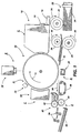
- FIG. 1 schematically depicts the various components of an illustrative electrophotographic printing machine having the developer of the present invention therein. It will become evident from the following discussion that this developer unit is equally well suited for use in a wide variety of printing machines and is not necessarily limited in its application to the particular printing machine described herein.
- the illustrative electrophotographic printing machine employs a drum 10 having a photoconductive surface adhering to a conductive substrate.
- the photoconductive surface comprises a selenium alloy with the conductive substrate being an electrically grounded aluminium alloy.
- Drum 10 moves in the direction of arrow 12 to advance successive portions of the photoconductive surface sequentially through the various processing stations disposed about the path of movement thereof.
- a corona generating device indicated generally by the reference numeral 14, charges the photoconductive surface to a relatively high, substantially uniform potential.
- Imaging station B includes an exposure system, indicated generally by the reference numeral 16.
- Exposure system 16 includes lamps which illuminate an original document positioned face down upon a transparent platen. The light rays reflected from the original document are transmitted through a lens to form a light image thereof. The light image is focused onto the charged portion of the photoconductive surface to selectively dissipate the charge thereon. This records an electrostatic latent image on the photoconductive surface which corresponds to the information in the original document.
- a modulated beam of energy i.e. a laser beam, or other suitable device, such as light emitting diodes, may be used to irradiate the charged portion of the photoconductive surface so as to record selected information thereon. Information from a computer may be employed to modulate the laser beam.
- drum 10 advances the electrostatic latent image to development station C.
- a magnetic brush developer unit indicated generally by the reference numeral 18, transports a developer material of magnetic carrier granules having toner particles adhering triboelectrically thereto closely adjacent to, or into contact with the electrostatic latent image. Toner particles are attracted from the carrier granules to the latent image forming a toner powder image.
- toner particles and a small amount of carrier granules are continually added to the developer material so that the life of the developer material is at least equal to the useful life of the electrophotographic printing machine. Excess developer material exits the developer unit through an exit port which has a toner particle impervious seal. The seal is pervious to carrier granules and developer material.
- Drum 10 then advances the toner powder image to transfer station D.
- a sheet of support material is moved into contact with the toner powder image.
- the sheet of support material is advanced to transfer station D by a sheet feeding apparatus, indicated generally by the reference numeral 20.
- sheet fading apparatus 20 includes a feed roll 22 contacting the uppermost sheet of a stack of sheets 24.
- Feed roll 22 rotates in the direction of arrow 26 to advance the uppermost sheet into a nip defined by forwarding rollers 28.
- Forwarding rollers 28 rotate in the direction of arrow 30 to advance the sheet into chute 32.
- Chute 32 directs the advancing sheet into contact with the photoconductive surface in a time sequence so that the toner powder image developed thereon contacts the advancing sheet at transfer station D.
- Transfer station D includes a corona generating device 34 which sprays ions onto the backside of the sheet. This attracts the toner powder image from the photoconductive surface to the sheet. After transfer, the sheet continues to move in the direction of arrow 36 on conveyor 38 to advance to fusing station E.
- Fusing station E includes a fuser assembly, indicated generally by the reference numeral 40, which permanently affixes the transferred toner powder image to the sheet.
- fuser assembly 40 includes a heated fuser roller 42 and a back-up roller 44. The sheet passes between fuser roller 42 and back-up roller 44 with the powder image contacting fuser roller 42. In this manner, the toner powder image is permanently affixed to the sheet.
- forwarding rollers 46 advance the sheet to catch tray 48 for subsequent removal from the printing machine by the operator.
- drum 10 rotates the photoconductive surface to cleaning station F.
- cleaning station F a cleaning system, indicated generally by the reference numeral 50, removes the residual particles adhering to the photoconductive surface.. In this way, the residual toner particles are removed from the photoconductive surface.
- Developer unit 18 includes a developer housing 52 defining a chamber 66 storing a supply of developer material including carrier granules and toner particles therein.
- a tubular member or sleeve 56 is mounted rotatably on shaft 58 in chamber 66 of housing 52.
- An elongated cylindrical magnet 60 is mounted interiorly of sleeve 56. Magnet 60 is mounted stationarily and has a plurality of magnetic poles impressed upon the circumferential surface thereof to generate a magnet field.
- a motor (not shown) rotates sleeve 56 in the direction of arrow 62. As sleeve 56 rotates in chamber 66 of housing 52, the developer material is attracted thereto.
- sleeve 56 transports the developer material attracted thereto closely adjacent to or into contact with the photoconductive surface. In the development zone, the toner particles are attracted from the carrier granules to the latent image recorded on the photoconductive surface of drum 10.
- a voltage source electrically biases sleeve 56 to a suitable polarity and magnitude so that the toner particles are deposited on the latent image.
- sleeve 56 is made from aluminium with magnet 60 being made from barium ferrite.
- a supply of developer material 64 is stored in chamber 66 of housing 52.
- Sleeve 56 is mounted in chamber 66 of housing 52 with a portion thereof extending outwardly through an opening in housing 52 so that the developer material is readily advanced, during the rotation of sleeve 56 in the direction of arrow 62, to the latent image recorded on the photoconductive surface of drum 10.
- toner particles are depleted therefrom and must be replenished.
- the carrier granules age and the entire developer material package, i.e. carrier granules and toner particles, must be periodically replaced in order to maintain the requisite copy quality.
- a discharging unit indicated generally by the reference numeral 68, dispenses a small quantity of carrier granules and the requisite amount of toner particles to developer material 64.
- Discharging unit 68 is shown as being located in chamber 66 of housing 52. However, one skilled in the art will appreciate that it may be located remotely therefrom as well.
- Discharging unit 68 includes an open ended hopper 70 having a foam roller 72 positioned in the open end thereof. A mixture of carrier granules and toner particles is stored in hopper 70.
- carrier granules and toner particles are discharged from hopper 70 to developer material 64 in chamber 66 of housing 52.
- the ratio of toner particles to carrier granules by weight being discharged from hopper 70 is substantially greater than the ratio of toner particles to carrier granules by weight in developer material 64.
- the developer material being dispensed from discharging unit 68 may be 25% carrier granules by weight and 75% toner particles by weight with developer material 64 in chamber 66 of housing 52 being about 96% carrier granules by weight and 4% toner particles by weight.
- An exit port 74 is located in the side wall of housing 52. As the quantity of developer material 64 exceeds a predetermined amount, i.e. as dictated by the location of exit port 74 in the side wall of housing 52, the extraneous developer material exits chamber 66 via exit port 74 and is discharged to waste container 76. Waste container 76 may be periodically emptied by the machine operator.
- a stand pipe may be used. The height of the stand pipe determines the amount of developer material in the developer housing chamber with the extraneous developer material being discharged from the bottom opening of the stand pipe to the waste container.
- the magnetic flux field attracts the magnetic carrier granules forming a carrier bead curtain across the opening of exit port 74.
- the carrier bead curtain permits developer material and denuded carrier granules to pass through the opening in the exit port to exit to waste container 76.
- the carrier bead curtain prevent toner particles from exiting chamber 66 of housing 52 through exit port 74.
- the toner particles are confined to chamber 66 of housing 52 while the extraneous developer material and denuded carrier granules are removed therefrom.
- magnet 78 is preferably a ring magnet with its opening aligned with the opening in the exit port.
- magnet 78 when the exit port is a slot, magnet 78 preferably includes a pair of bar magnets, one bar magnet positioned on either side of the slot. In either case, magnet 78 generates a magnetic flux field which attracts the magnetic carrier granules to form a carrier bead curtain across the opening in exit port 74 which prevents the passage of toner particles therethrough while permitting the passage of developer material and denuded carrier granules.
- the developer unit of the present invention has toner particles and carrier granules added to the developer material therein.
- Extraneous developer material and denuded carrier granules exit through an exit port which has a carrier bead curtain formed over the opening thereof.
- the carrier bead curtain permits the passage of developer material and denuded carrier granules through the exit port while preventing the passage of toner particles therethrough. This insures that toner particles do not escape from the developer unit contaminating the other components of the printing machine and degrading copy quality.
Landscapes
- Physics & Mathematics (AREA)
- General Physics & Mathematics (AREA)
- Dry Development In Electrophotography (AREA)
Claims (7)
- Vorrichtung (18) zum Entwickeln eines elektrostatischen latenten Abbildes, das in einer Druckmaschine verwendet wird, welche Vorrichtung umfaßt:
Mittel (56, 60) zum Transportieren eines mindestens Magnet-Trägerkörner mit daran durch Reibungselektrizität anhängenden Tonerpartikeln umfassenden Entwicklermaterials in Berührung mit dem elektrostatischen latenten Abbild;
ein eine Kammer (66) mit einem Vorrat von Entwicklermaterial bestimmendes Gehäuse, wobei das Transportmittel (56, 60) mit der Kammer des Gehäuses zur Aufnahme von Entwicklermaterial in Verbindung ist, das Gehäuse eine Austrittsöffnung (74) besitzt, die in einer ausgewählten Position in der Kammer des Gehäuses über dem Niveau der Grundseite der Kammer angeordnet ist, um das Austreten von Entwicklermaterial aus der Kammer zu ermöglichen, wenn das Niveau des Entwicklermaterials in dieser mindestens einen Anteil der Austrittsöffnung überdeckt; und
Mittel (68) zum Abgeben von Tonerpartikeln und Trägerkörnern in die Kammer des Gehäuses; gekennzeichnet durch ein Magnetteil (78), das der Austrittsöffnung (74) des Gehäuses benachbart positioniert ist, wobei mindestens zwei Teile des Magnetteils einander gegenüberliegend an gegenüberliegenden Seiten der Austrittsöffnung angeordnet sind zum Erzeugen eines Magnetflußfeldes in dem Bereich der Austrittsöffnung des Gehäuses, um mindestens einen Trägerschicht-Vorhang zu bilden, welcher den Durchtritt von Tonerpartikeln durch die Austrittsöffnung verhindert. - Vorrichtung nach Anspruch 1, dadurch gekennzeichnet, daß die Austrittsöffnung kreisförmig und das Magnetteil ein Ringmagnet ist, dessen Öffnung mit der Austrittsöffnung ausgerichtet ist.
- Vorrichtung nach Anspruch 1, dadurch gekennzeichnet, daß die Austrittsöffnung ein Schlitz ist, und daß das Magnetteil ein Paar von Stabmagneten enthält, von denen je ein Magnet zu beiden Seiten des Schlitzes angeordnet ist.
- Vorrichtung nach einem der Ansprüche 1 bis 3, bei der das Gewichtsverhältnis von Tonerteilchen zu Trägerkörnern in der durch das Abgabemittel (68) zu der Kammer (66) des Gehäuses hinzugefügten Zugabe wesentlich größer als das Gewichtsverhältnis von Tonerteilchen zu Trägerkörnern in der Kammer des Gehäuses ist.
- Vorrichtung nach einem der Ansprüche 1 bis 4, bei der das Abgabemittel (68) Mittel (70) zum Speichern eines Vorrats von Trägerkörnern und Tonerpartikeln enthält.
- Vorrichtung nach einem der Ansprüche 1 bis 5, bei der das Transportmittel eine magnetische Entwicklerwalze umfaßt.
- Elektrophotographische Druckmaschine des Typs, der ein an einem photoleitenden Teil aufgezeichnetes elektrostatisches latentes Bild und Mittel zum Entwickeln des latenten Bildes besitzt, welche die Vorrichtung nach einem der Ansprüche 1 bis 6 umfassen.
Applications Claiming Priority (2)
| Application Number | Priority Date | Filing Date | Title |
|---|---|---|---|
| US07/229,072 US4891673A (en) | 1988-08-04 | 1988-08-04 | Development system |
| US229072 | 1988-08-04 |
Publications (3)
| Publication Number | Publication Date |
|---|---|
| EP0354030A2 EP0354030A2 (de) | 1990-02-07 |
| EP0354030A3 EP0354030A3 (de) | 1991-10-23 |
| EP0354030B1 true EP0354030B1 (de) | 1994-10-26 |
Family
ID=22859739
Family Applications (1)
| Application Number | Title | Priority Date | Filing Date |
|---|---|---|---|
| EP89307892A Expired - Lifetime EP0354030B1 (de) | 1988-08-04 | 1989-08-03 | Entwicklungssystem |
Country Status (4)
| Country | Link |
|---|---|
| US (1) | US4891673A (de) |
| EP (1) | EP0354030B1 (de) |
| JP (1) | JPH0658570B2 (de) |
| DE (1) | DE68919013T2 (de) |
Families Citing this family (16)
| Publication number | Priority date | Publication date | Assignee | Title |
|---|---|---|---|---|
| US5019870A (en) * | 1990-03-26 | 1991-05-28 | Xerox Corporation | Toner removal apparatus |
| US5095338A (en) * | 1991-02-21 | 1992-03-10 | Xerox Corporation | Developer which discharges used carrier particles using a magnetic valve |
| US5138382A (en) * | 1991-03-27 | 1992-08-11 | Xerox Corporation | Apparatus and method for creating a developer housing seal via a curtain of carrier beads |
| JP2865451B2 (ja) * | 1991-07-29 | 1999-03-08 | シャープ株式会社 | 画像形成装置 |
| JPH05150627A (ja) * | 1991-11-29 | 1993-06-18 | Sharp Corp | 現像装置 |
| US5440376A (en) * | 1992-04-07 | 1995-08-08 | Sharp Kabushiki Kaisha | Electrophotographic apparatus |
| US5430532A (en) * | 1993-03-09 | 1995-07-04 | Sharp Kabushiki Kaisha | Developing device with a tilt detecting function designed for a trickle system |
| US5355199A (en) * | 1993-09-24 | 1994-10-11 | Xerox Corporation | Development unit for an electrophotographic printer having a torque-triggered outlet port |
| US5436703A (en) * | 1994-05-02 | 1995-07-25 | Xerox Corporation | Development unit for electrostatographic printing having a spillover barrier for used developer material |
| US5839017A (en) * | 1997-04-09 | 1998-11-17 | Xerox Corporation | Developer level detection system |
| US6353722B1 (en) | 2000-12-19 | 2002-03-05 | Xerox Corporation | Waste bottle with overflow chamber |
| US6587661B1 (en) * | 2002-01-30 | 2003-07-01 | Kabushiki Kaisha Toshiba | Image forming apparatus |
| JP2005345494A (ja) * | 2004-05-31 | 2005-12-15 | Ricoh Co Ltd | 現像装置およびプロセスカートリッジおよび画像形成装置 |
| US8045897B2 (en) * | 2008-09-17 | 2011-10-25 | Kabushiki Kaisha Toshiba | Developing device |
| US20110176837A1 (en) * | 2010-01-21 | 2011-07-21 | Kabushiki Kaisha Toshiba | Developing apparatus and image forming apparatus |
| JP6938891B2 (ja) | 2016-10-18 | 2021-09-22 | 富士フイルムビジネスイノベーション株式会社 | 現像装置及び画像形成装置 |
Family Cites Families (8)
| Publication number | Priority date | Publication date | Assignee | Title |
|---|---|---|---|---|
| US4101211A (en) * | 1976-07-12 | 1978-07-18 | Eastman Kodak Company | Magnetic curtain seal for development apparatus |
| US4387982A (en) * | 1981-07-01 | 1983-06-14 | Xerox Corporation | Charged particle containment apparatus |
| US4394086A (en) * | 1982-03-24 | 1983-07-19 | Xerox Corporation | Particle containment apparatus |
| US4697914A (en) * | 1982-06-30 | 1987-10-06 | Xerox Corporation | Toner containment method and apparatus |
| JPS59100471A (ja) * | 1982-12-01 | 1984-06-09 | Fuji Xerox Co Ltd | 電子写真複写機用現像装置 |
| EP0221281B1 (de) * | 1985-10-09 | 1988-11-30 | Siemens Aktiengesellschaft | Vorrichtung zum Entfernen eines, eine magnetische Komponente enthaltenden Entwicklergemisches aus einer Entwicklerstation eines nichtmechanischen Druck- oder Kopiergerätes |
| US4614165A (en) * | 1985-11-25 | 1986-09-30 | Xerox Corporation | Extended life development system |
| US4775874A (en) * | 1986-06-20 | 1988-10-04 | Siemens Aktiegesellschaft | Magnetic closing and conveying mechanism for non-mechanical printer or copier devices |
-
1988
- 1988-08-04 US US07/229,072 patent/US4891673A/en not_active Expired - Lifetime
-
1989
- 1989-07-27 JP JP1195389A patent/JPH0658570B2/ja not_active Expired - Lifetime
- 1989-08-03 DE DE68919013T patent/DE68919013T2/de not_active Expired - Lifetime
- 1989-08-03 EP EP89307892A patent/EP0354030B1/de not_active Expired - Lifetime
Also Published As
| Publication number | Publication date |
|---|---|
| DE68919013D1 (de) | 1994-12-01 |
| EP0354030A2 (de) | 1990-02-07 |
| EP0354030A3 (de) | 1991-10-23 |
| US4891673A (en) | 1990-01-02 |
| DE68919013T2 (de) | 1995-05-04 |
| JPH0274973A (ja) | 1990-03-14 |
| JPH0658570B2 (ja) | 1994-08-03 |
Similar Documents
| Publication | Publication Date | Title |
|---|---|---|
| US5095338A (en) | Developer which discharges used carrier particles using a magnetic valve | |
| EP0354030B1 (de) | Entwicklungssystem | |
| US4614165A (en) | Extended life development system | |
| US5355199A (en) | Development unit for an electrophotographic printer having a torque-triggered outlet port | |
| US4697914A (en) | Toner containment method and apparatus | |
| CA1171269A (en) | Development system | |
| US5253016A (en) | Contaminant control for scavengeless development in a xerographic apparatus | |
| US4492321A (en) | Apparatus for dispensing toner particles and sealing the storage chamber thereof | |
| US4155329A (en) | Magnetic brush developing device | |
| EP0533347B1 (de) | Entwicklungssystem | |
| US4387982A (en) | Charged particle containment apparatus | |
| US5422709A (en) | Electrode wire grid for developer unit | |
| US5053824A (en) | Scavengeless development apparatus having a donor belt | |
| US4080054A (en) | Device for replenishing toner particles | |
| US6351623B1 (en) | Toner dispensing apparatus employing a traveling wave transport grid | |
| US5138382A (en) | Apparatus and method for creating a developer housing seal via a curtain of carrier beads | |
| EP0130832B1 (de) | Entwicklungssystem mit mehreren Geschwindigkeiten | |
| CA1184591A (en) | Magnetic brush cleaning system | |
| EP0026678B1 (de) | Elektrostatographische Kopiermaschine | |
| US5697018A (en) | Air handling system for a development housing | |
| US4394086A (en) | Particle containment apparatus | |
| JPS6359145B2 (de) | ||
| US4163614A (en) | Closed loop particle dispenser | |
| US5140373A (en) | Electrostatic latent image developing apparatus with bristle height adjusting member | |
| EP0032424B1 (de) | Entwicklungsvorrichtung für latente Bilder |
Legal Events
| Date | Code | Title | Description |
|---|---|---|---|
| PUAI | Public reference made under article 153(3) epc to a published international application that has entered the european phase |
Free format text: ORIGINAL CODE: 0009012 |
|
| AK | Designated contracting states |
Kind code of ref document: A2 Designated state(s): DE FR GB |
|
| PUAL | Search report despatched |
Free format text: ORIGINAL CODE: 0009013 |
|
| AK | Designated contracting states |
Kind code of ref document: A3 Designated state(s): DE FR GB |
|
| 17P | Request for examination filed |
Effective date: 19920402 |
|
| 17Q | First examination report despatched |
Effective date: 19930217 |
|
| GRAA | (expected) grant |
Free format text: ORIGINAL CODE: 0009210 |
|
| AK | Designated contracting states |
Kind code of ref document: B1 Designated state(s): DE FR GB |
|
| REF | Corresponds to: |
Ref document number: 68919013 Country of ref document: DE Date of ref document: 19941201 |
|
| ET | Fr: translation filed | ||
| PLBE | No opposition filed within time limit |
Free format text: ORIGINAL CODE: 0009261 |
|
| STAA | Information on the status of an ep patent application or granted ep patent |
Free format text: STATUS: NO OPPOSITION FILED WITHIN TIME LIMIT |
|
| 26N | No opposition filed | ||
| REG | Reference to a national code |
Ref country code: GB Ref legal event code: IF02 |
|
| PGFP | Annual fee paid to national office [announced via postgrant information from national office to epo] |
Ref country code: DE Payment date: 20080814 Year of fee payment: 20 |
|
| PGFP | Annual fee paid to national office [announced via postgrant information from national office to epo] |
Ref country code: FR Payment date: 20080818 Year of fee payment: 20 |
|
| PGFP | Annual fee paid to national office [announced via postgrant information from national office to epo] |
Ref country code: GB Payment date: 20080813 Year of fee payment: 20 |
|
| REG | Reference to a national code |
Ref country code: GB Ref legal event code: PE20 Expiry date: 20090802 |
|
| PG25 | Lapsed in a contracting state [announced via postgrant information from national office to epo] |
Ref country code: GB Free format text: LAPSE BECAUSE OF EXPIRATION OF PROTECTION Effective date: 20090802 |