EP0353996B1 - A flow sensor - Google Patents
A flow sensor Download PDFInfo
- Publication number
- EP0353996B1 EP0353996B1 EP89307812A EP89307812A EP0353996B1 EP 0353996 B1 EP0353996 B1 EP 0353996B1 EP 89307812 A EP89307812 A EP 89307812A EP 89307812 A EP89307812 A EP 89307812A EP 0353996 B1 EP0353996 B1 EP 0353996B1
- Authority
- EP
- European Patent Office
- Prior art keywords
- flow sensor
- substrate
- heating element
- temperature detecting
- zirconia
- Prior art date
- Legal status (The legal status is an assumption and is not a legal conclusion. Google has not performed a legal analysis and makes no representation as to the accuracy of the status listed.)
- Expired - Lifetime
Links
Images

Classifications
-
- G—PHYSICS
- G01—MEASURING; TESTING
- G01F—MEASURING VOLUME, VOLUME FLOW, MASS FLOW OR LIQUID LEVEL; METERING BY VOLUME
- G01F1/00—Measuring the volume flow or mass flow of fluid or fluent solid material wherein the fluid passes through a meter in a continuous flow
- G01F1/68—Measuring the volume flow or mass flow of fluid or fluent solid material wherein the fluid passes through a meter in a continuous flow by using thermal effects
- G01F1/684—Structural arrangements; Mounting of elements, e.g. in relation to fluid flow
- G01F1/688—Structural arrangements; Mounting of elements, e.g. in relation to fluid flow using a particular type of heating, cooling or sensing element
- G01F1/69—Structural arrangements; Mounting of elements, e.g. in relation to fluid flow using a particular type of heating, cooling or sensing element of resistive type
- G01F1/692—Thin-film arrangements
-
- G—PHYSICS
- G01—MEASURING; TESTING
- G01F—MEASURING VOLUME, VOLUME FLOW, MASS FLOW OR LIQUID LEVEL; METERING BY VOLUME
- G01F1/00—Measuring the volume flow or mass flow of fluid or fluent solid material wherein the fluid passes through a meter in a continuous flow
- G01F1/68—Measuring the volume flow or mass flow of fluid or fluent solid material wherein the fluid passes through a meter in a continuous flow by using thermal effects
- G01F1/696—Circuits therefor, e.g. constant-current flow meters
- G01F1/698—Feedback or rebalancing circuits, e.g. self heated constant temperature flowmeters
- G01F1/699—Feedback or rebalancing circuits, e.g. self heated constant temperature flowmeters by control of a separate heating or cooling element
Definitions
- This invention relates to a flow sensor that comprises a heating element and a fluid temperature detecting element, which are formed on a substrate.
- a conventional flow sensor comprises a heater, which is placed within a bypass flow tube connected to a main flow tube. A part of the main flow of fluid is directed to the bypass flow tube in which the fluid is heated by the heater. The flow rate is determined by the fluid-temperature distribution in the direction of the flow in the bypass flow path.
- a flow sensor of this type can detect the flow rate accurately so that it is widely used as a mass-flow controller for semiconductor gases, or the like. This flow sensor, however, is not suited for miniaturization or mass production because it requires a bypass flow tube, which makes the whole structure of the sensor complicated. Moreover, its production cost is so high that it can only be applied to a limited field.
- Another conventional flow sensor comprises a heating element and a fluid temperature detecting element which are placed within a flow path.
- the heating element heats fluid around it and the amount of heat transferred from the heating element to the fluid is detected by the fluid temperature detecting element.
- the detected value is used to determine the flow rate of the fluid.
- the difference in temperature between the fluid and the heating element is maintained at a fixed level, so as to compensate for the influence of the fluid temperature on the value of the flow rate to be detected.
- the output of the flow sensor can be enhanced by setting the above-mentioned difference in temperature at a high level.
- One of the known flow sensors of this type comprises a heating transistor and a fluid temperature detecting transistor, both of which are formed on a silicon chip.
- This flow sensor can be mass-produced by the use of a silicon processing technique, but it is disadvantageous in that the temperature characteristics vary between the sensors. Thus, it is difficult to obtain sensors having the desired temperature characteristics.
- An apparatus of this type for determining the flow rate of a flowing medium is known from US-A-4777820, having a substrate as a carrier and a resistor arrangement disposed on the substrate which, among other elements, includes a layer-like resistor (RH) as well as a layer-like heating resistor (Rs), the heating output of which is regulated such that the measuring resistor (RH) has a constant temperature.
- the measuring resistor (RH) and the heating resistor (Rs) are located on a downstream portion of the substrate, on a lip set off by a slit whereby soiling of the substrate affects the measurement result to only a small extent.
- Resistor wires made of materials having high melting points such as platinum, tungsten, or the like, are often used as the heating element and the fluid temperature detecting element for this type of flow sensor, but the resistance of the wire made of these materials is small and varies between the elements, so that adjustability of the heating temperature and accuracy of the temperature measurement of the sensor are poor.
- a hot film type air flow meter of the latter type is known from GB-A-2194346 having a temperature sensing exothermic resistor.
- the resistor comprises a ceramic body in the form of a bobbin with respective leads bonded to both ends thereof.
- a metallic film is formed on the ceramic body and this film contains a spiral groove to result in a spiral metal conductor on the ceramic body.
- the metallic film and ceramic body are covered by a layer of glass.
- the resistor is mounted upstream of a similarly constructed temperature-compensating resistor within a gas-flow passage.
- Another known hot wire air flow meter is that described in GB-A-2196433 which comprises a heated sensing resistor formed on a bobbin of low thermal conductivity made from zirconia or glass fibre.
- a helical platinum film or wire is formed on the surface of the bobbin. The ends of the resistor are supported by respective conductors and a protective glass coating is applied overall.
- a thermal film-type flow sensor comprising a thin-film heating element and a thin-film fluid temperature detecting element that are respectively formed on two separate heat-insulating substrates.
- This type of flow sensor can be miniaturized by the use of a fine patterned thin metal film.
- this flow sensor can be obtained by a process in which a single substrate having a number of thin-film elements formed thereon are cut out into each unit, resulting in a number of units with uniform characteristics at the same time.
- the sensor can be readily mass produced with uniform sensor-characteristics.
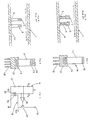
- FIG. 7 of the accompanying drawings shows the above-mentioned thermal thin-film type flow sensor fixed within a flow path 1.
- Fluid flows from L to R within the flow path 1 in the direction indicated by the arrow.
- a fluid temperature detecting unit 2 is disposed upstream of a heating unit 3, whereby the fluid temperature detecting unit 2 should not be directly influenced by the heat of the heating unit 3.
- Both the units 2 and 3 comprise lead terminals, which are mechanically and electrically connected to sockets 5 via supports 4.
- the sockets 5 are attached to the wall la of the flow path 1. In this flow sensor, when the temperature of the wall la is different from that of the fluid, heat travels to and fro between the wall la and the fluid temperature detecting unit 2 via the supports 4.
- a flow sensor shown in Figure 8 in which the units 2 and 3 are directly connected to the socket 5 on the wall la without the supports 4, has been proposed.
- the substrates, on each of which the thin-film heating element and the thin-film fluid temperature detecting element are respectively formed, are connected to the sockets 5 without the supports 4.
- heat does not travel between the fluid temperature detecting unit 2 and the wall 1a, and heat of the heating unit 3 is not conducted to the wall 1a, because a heat-insulation effect is obtained between the heating element and the wall 1a and also between the fluid temperature detecting element and the wall 1a due to the heat-insulating substrates.
- the substrate materials having high thermal conductivity, i.e., silicon, alumina, or the like, are often used.
- the substrates in order to obtain sufficient heat-insulation effect between the two elements and the wall 1a, the substrates should be made larger in size because of their high thermal conductivity.
- glass which has low thermal conductivity, has been proposed as a material for the substrate (Preprints on the sixth symposium "Basics and Application of Sensors” sponsored by Electronic Device Tecnique Committee of Electrical Society, pp. 95-96).
- glass is used as the material for the substrates, they can be made smaller because sufficient heat-insulation effect can be obtained between the elements and the wall 1a even with smaller substrates due to their low thermal conductivity.
- Glass is also advantageous in that it is inexpensive and the substrates made of it can be used under a relatively wide variety of environmental conditions. Glass, however, has only a small mechanical strength, so that it is difficult to process glass into a substrate, and the substrate made of it is fragile and difficult to handle. Glass does not have sufficient heat resistance, so that the glass substrate cannot be used in a high-temperature atmosphere, and the sensor comprising the glass substrate cannot be cleaned by being heated by its heating element.
- a flow sensor comprising a substrate made of pure zirconia or zirconia ceramic, a heating element formed on one end of a surface of said substrate, and a fluid temperature detecting element directly formed on the surface of said substrate at the other end of said substrate, said heating element and fluid temperature detecting element being thermally isolated from each other by virtue of said substrate.
- the flow sensor can also comprises a heating temperature detecting element for detecting the temperature of said heating element, in order to control the temperature, said heating temperature detecting element being formed on said substrate in the vicinity of said heating element.
- the zirconia ceramic may, for example, be stabilized zirconia that is produced by the addition of a stabilizer of Y2O3, CaO, or MgO to pure zirconia, or be partially-stabilized zirconia that is produced by the addition to pure zirconia of an amount of a stabilizer of Y2O3, CaO, or MgO less than the amount of stabilizer needed to produce stabilized zirconia.
- the invention described herein makes possible the provision of (1) a flow sensor of a reduced size for detecting the rate of flow with accuracy; (2) a flow sensor that can be readily mass-produced and can be used under a wide variety of environmental conditions; (3) a flow sensor that can be used in a high-temperature atmosphere; and (4) a flow sensor that can be cleaned by being heated by its heating element.
- Figure 1 shows a thermal film-type flow sensor 30 in accordance with the present invention, comprising a heating element 10 and a fluid temperature detecting element 13, both formed on a common heat-insulating substrate 11.
- the substrate 11 is rectangular in shape and is made of zirconia, which is a heat-insulating material having low thermal conductivity, high mechanical strength and excellent heat-resistance. Thus, because it is made of zirconia, the portion of the substrate 11 corresponding to the area between the elements 10 and 13 provides insulation against heat transfer therebetween.
- the heating element 10 and the fluid temperature detecting element 13 each have a pair of lead terminals 19 attached thereto, through which the output from the heating element 10 and the fluid temperature detecting element 13 is delivered.
- the lead terminals 19 pass through a box-shaped socket 21, which in use is attached to a fluid-path wall 20a as shown in Figure 4, so as to mechanically connect the heating element 10 and the fluid temperature detecting element 13 to the wall 20a.
- the heating element 10 and the fluid temperature detecting element 13 are formed as follows: On the substrate 11, a thin metal film of platinum or the like having a high resistance temperature coefficient is formed by the vacuum vapour deposition method, the sputtering method, plasma assisted chemical vapour deposition, or the like. Then, thin metal films are patterned by an etching technique, and adjusted to have a predetermined resistance by means of a laser trimming apparatus, resulting in, as shown in Figure 1, the heating element 10 and the fluid temperature detecting element 13.
- the heating element 10 and the fluid temperature detecting element 13 are connected to electrical resistors R1 and R2, respectively, resulting in a bridge circuit A as shown in Figure 3.
- the bridge circuit A is connected to a feedback circuit B including an amplifier 16 and a transistor 17.
- the difference in voltage between a connection point C1 (between the resistor R1 and the fluid temperature detecting element 13) and a connection point C2 (between the resistor R2 and the heating element 10) is amplified by the amplifier 16 so that the base potential of the transistor 17 is controlled, allowing the transistor 17 to be driven.
- the emitter terminal of the transitor 17 is connected to both of the electrical resistors R1 and R2.
- the transistor 17 is also connected to an input terminal 18.
- the transistor 17 is turned on to receive electric current through the input terminal 18, which electrifies the heating element 10, so that the heating element 10 generates heat.
- the flow rate of the fluid is high, a large amount of heat is transferred from the heating element 10 to the fluid.
- the flow rate of the fluid is low, a small amount of heat is transferred from the heating element 10 to the fluid.
- the temperature of the fluid is detected by the fluid temperature detecting element 13, and the difference in temperature between the fluid and the heating element 10 is maintained at a fixed level with the aid of the feedback circuit B; that is, the feedback circuit B controls the current that is applied to the heating element 10 in such a manner that the current is increased when the flow rate is high and is decreased when the flow rate is low. Accordingly, the level of voltage Vout obtained at the heating element 10 changes with the flow rate, so that the flow rate of the fluid can be determined by changes in the voltage Vout.
- the thermal conductivity of zirconia which is used as the material for the heat-insulating substrate 11 in this example, is 4.6 x 10 ⁇ 3cal/cm s C. This is far lower than the thermal conductivity of alumina and silicon, which are often used as the material for the heat-insulating substance of a conventional flow sensor.
- the thermal conductivity of the material for the substrate is as high as that of alumina or silicon, the heat generated by the heating element is readily conducted through the substrate to the wall of the flow path, from which the heat is directly conducted to the fluid temperature detecting unit. This interferes with the accurate measurement with use of the fluid temperature detecting unit.
- the substrate in order to prevent the heat from being conducted to the wall of the flow path, the substrate should be made large in size.
- the thermal conductivity of zirconia is extremely small as described above, so that heat generated by the heating element is not conducted to the fluid temperature detecting element 13 even though the substrate is made smaller in size.
- Zirconia is also excellent in mechanical strength.
- its flexural strength is as great as 120kg/mm, which is far greater than that of quartz glass and alumina as shown in the table of Figure 4, so that it is easy to handle in the production process, resulting in a high yield.
- the great flexural strength of zirconia also makes it possible to use a flow sensor under a wider variety of environmental conditions.
- zirconia has such a high heat-resistance that a flow sensor comprising zirconia substrates can be used in a high-temperature atmosphere and also can clean itself by the heat of its heating element.
- Zirconia used as the material for the substrates of the flow sensor of the invention is not limited to a pure zirconia; it can also be a zirconia ceramic, i.e., a stabilized zirconia which is produced by the addition of a stabilizer such as Y2O3, CaO, MgO, or the like to the pure zirconia, or a partially-stabilized zirconia which is produced by the addition of a smaller amount of the above-mentioned stabilizer to the pure zirconia.
- a zirconia ceramic i.e., a stabilized zirconia which is produced by the addition of a stabilizer such as Y2O3, CaO, MgO, or the like to the pure zirconia, or a partially-stabilized zirconia which is produced by the addition of a smaller amount of the above-mentioned stabilizer to the pure zirconia.
- FIG 2 shows an example of a flow sensor in accordance with the present invention, which, compared to the arrangement of Figure 1, additionally comprises a heating temperature detecting element 22 incorporated on the substrate 11 adjacent to the heating element 10.
- the detecting element 22 detects the temperature of the heating element 10 so that the temperature of the heating element 10 can be controlled.
- the bridge circuit A is constituted by the fluid temperature detecting element 13 and the heating temperature detecting element 22.
- the heating element 10 is not included in the bridge circuit A.
Landscapes
- Physics & Mathematics (AREA)
- Fluid Mechanics (AREA)
- General Physics & Mathematics (AREA)
- Measuring Volume Flow (AREA)
Description
- This invention relates to a flow sensor that comprises a heating element and a fluid temperature detecting element, which are formed on a substrate.
- A conventional flow sensor comprises a heater, which is placed within a bypass flow tube connected to a main flow tube. A part of the main flow of fluid is directed to the bypass flow tube in which the fluid is heated by the heater. The flow rate is determined by the fluid-temperature distribution in the direction of the flow in the bypass flow path. A flow sensor of this type can detect the flow rate accurately so that it is widely used as a mass-flow controller for semiconductor gases, or the like. This flow sensor, however, is not suited for miniaturization or mass production because it requires a bypass flow tube, which makes the whole structure of the sensor complicated. Moreover, its production cost is so high that it can only be applied to a limited field.
- Another conventional flow sensor comprises a heating element and a fluid temperature detecting element which are placed within a flow path. The heating element heats fluid around it and the amount of heat transferred from the heating element to the fluid is detected by the fluid temperature detecting element. The detected value is used to determine the flow rate of the fluid. In a flow sensor of this type, the difference in temperature between the fluid and the heating element is maintained at a fixed level, so as to compensate for the influence of the fluid temperature on the value of the flow rate to be detected. The output of the flow sensor can be enhanced by setting the above-mentioned difference in temperature at a high level.
- One of the known flow sensors of this type, comprises a heating transistor and a fluid temperature detecting transistor, both of which are formed on a silicon chip. This flow sensor can be mass-produced by the use of a silicon processing technique, but it is disadvantageous in that the temperature characteristics vary between the sensors. Thus, it is difficult to obtain sensors having the desired temperature characteristics. An apparatus of this type for determining the flow rate of a flowing medium is known from US-A-4777820, having a substrate as a carrier and a resistor arrangement disposed on the substrate which, among other elements, includes a layer-like resistor (RH) as well as a layer-like heating resistor (Rs), the heating output of which is regulated such that the measuring resistor (RH) has a constant temperature. The measuring resistor (RH) and the heating resistor (Rs) are located on a downstream portion of the substrate, on a lip set off by a slit whereby soiling of the substrate affects the measurement result to only a small extent.
- Resistor wires made of materials having high melting points such as platinum, tungsten, or the like, are often used as the heating element and the fluid temperature detecting element for this type of flow sensor, but the resistance of the wire made of these materials is small and varies between the elements, so that adjustability of the heating temperature and accuracy of the temperature measurement of the sensor are poor.
- A hot film type air flow meter of the latter type is known from GB-A-2194346 having a temperature sensing exothermic resistor. The resistor comprises a ceramic body in the form of a bobbin with respective leads bonded to both ends thereof. A metallic film is formed on the ceramic body and this film contains a spiral groove to result in a spiral metal conductor on the ceramic body. The metallic film and ceramic body are covered by a layer of glass. In use, the resistor is mounted upstream of a similarly constructed temperature-compensating resistor within a gas-flow passage. Another known hot wire air flow meter is that described in GB-A-2196433 which comprises a heated sensing resistor formed on a bobbin of low thermal conductivity made from zirconia or glass fibre. A helical platinum film or wire is formed on the surface of the bobbin. The ends of the resistor are supported by respective conductors and a protective glass coating is applied overall.
- It is a disadvantage in sensors of the latter types that they use fine wires of platinum, tungsten, or the like, which are extremely difficult to produce and thus cannot be mass-produced.
- In order to overcome the above-mentioned problems, a thermal film-type flow sensor comprising a thin-film heating element and a thin-film fluid temperature detecting element that are respectively formed on two separate heat-insulating substrates has been proposed. This type of flow sensor can be miniaturized by the use of a fine patterned thin metal film. Moreover, this flow sensor can be obtained by a process in which a single substrate having a number of thin-film elements formed thereon are cut out into each unit, resulting in a number of units with uniform characteristics at the same time. Thus, the sensor can be readily mass produced with uniform sensor-characteristics.
- Figure 7 of the accompanying drawings shows the above-mentioned thermal thin-film type flow sensor fixed within a flow path 1. Fluid flows from L to R within the flow path 1 in the direction indicated by the arrow. A fluid
temperature detecting unit 2 is disposed upstream of aheating unit 3, whereby the fluidtemperature detecting unit 2 should not be directly influenced by the heat of theheating unit 3. Both theunits sockets 5 viasupports 4. Thesockets 5 are attached to the wall la of the flow path 1. In this flow sensor, when the temperature of the wall la is different from that of the fluid, heat travels to and fro between the wall la and the fluidtemperature detecting unit 2 via thesupports 4. This prevents the accurate measurement of the fluid temperature with use of the fluidtemperature detecting unit 2. Also in this sensor, the heat of theheating unit 3 tends to be conducted through thesupports 4 to the wall la, from which the heat is then transferred to the fluidtemperature detecting unit 2. This prevents the fluidtemperature detecting unit 2 from detecting the temperature of the fluid with accuracy. - To solve this problem, a flow sensor shown in Figure 8 , in which the
units socket 5 on the wall la without thesupports 4, has been proposed. Thus, the substrates, on each of which the thin-film heating element and the thin-film fluid temperature detecting element are respectively formed, are connected to thesockets 5 without thesupports 4. In this flow sensor, heat does not travel between the fluidtemperature detecting unit 2 and thewall 1a, and heat of theheating unit 3 is not conducted to thewall 1a, because a heat-insulation effect is obtained between the heating element and thewall 1a and also between the fluid temperature detecting element and thewall 1a due to the heat-insulating substrates. - As materials for the substrate, materials having high thermal conductivity, i.e., silicon, alumina, or the like, are often used. In such a case, in order to obtain sufficient heat-insulation effect between the two elements and the
wall 1a, the substrates should be made larger in size because of their high thermal conductivity. In order to make the substrates smaller in size, glass, which has low thermal conductivity, has been proposed as a material for the substrate (Preprints on the sixth symposium "Basics and Application of Sensors" sponsored by Electronic Device Tecnique Committee of Electrical Society, pp. 95-96). When glass is used as the material for the substrates, they can be made smaller because sufficient heat-insulation effect can be obtained between the elements and thewall 1a even with smaller substrates due to their low thermal conductivity. Glass is also advantageous in that it is inexpensive and the substrates made of it can be used under a relatively wide variety of environmental conditions. Glass, however, has only a small mechanical strength, so that it is difficult to process glass into a substrate, and the substrate made of it is fragile and difficult to handle. Glass does not have sufficient heat resistance, so that the glass substrate cannot be used in a high-temperature atmosphere, and the sensor comprising the glass substrate cannot be cleaned by being heated by its heating element. - It is an object of the present invention to provide a flow sensor which overcomes the above-discussed and other disadvantages and deficiencies of the known devices.
- In accordance with the present invention, there is provided a flow sensor comprising a substrate made of pure zirconia or zirconia ceramic, a heating element formed on one end of a surface of said substrate, and a fluid temperature detecting element directly formed on the surface of said substrate at the other end of said substrate, said heating element and fluid temperature detecting element being thermally isolated from each other by virtue of said substrate.
- In some embodiments, the flow sensor can also comprises a heating temperature detecting element for detecting the temperature of said heating element, in order to control the temperature, said heating temperature detecting element being formed on said substrate in the vicinity of said heating element.
- The zirconia ceramic may, for example, be stabilized zirconia that is produced by the addition of a stabilizer of Y₂O₃, CaO, or MgO to pure zirconia, or be partially-stabilized zirconia that is produced by the addition to pure zirconia of an amount of a stabilizer of Y₂O₃, CaO, or MgO less than the amount of stabilizer needed to produce stabilized zirconia.
- The invention described herein makes possible the provision of (1) a flow sensor of a reduced size for detecting the rate of flow with accuracy; (2) a flow sensor that can be readily mass-produced and can be used under a wide variety of environmental conditions; (3) a flow sensor that can be used in a high-temperature atmosphere; and (4) a flow sensor that can be cleaned by being heated by its heating element.
- The invention is described further hereafter, by way of example only, with reference to the accompanying drawings, in which:
- Figure 1 is a sectional side elevation showing one embodiment of a flow sensor of this invention;
- Figure 2 is a sectional side elevation showing another flow sensor of this invention;
- Figure 3 is a circuit diagram incorporating the flow sensor shown in Figure 1;
- Figure 4 is a sectional side elevation of a flow sensor of this invention placed within a flow path;
- Figure 5 is a table indicating the properties of the materials used for substrates of a conventional flow sensor and of a flow sensor of this invention;
- Figure 6 is a circuit diagram incorporating the flow sensor of Figure 2;
- Figure 7 is a sectional side elevation showing a conventional flow sensor placed within a flow path; and
- Figure 8 is a sectional side elevation of another conventional flow sensor placed within a flow path.
- Figure 1 shows a thermal film-
type flow sensor 30 in accordance with the present invention, comprising aheating element 10 and a fluidtemperature detecting element 13, both formed on a common heat-insulating substrate 11. Thesubstrate 11 is rectangular in shape and is made of zirconia, which is a heat-insulating material having low thermal conductivity, high mechanical strength and excellent heat-resistance. Thus, because it is made of zirconia, the portion of thesubstrate 11 corresponding to the area between theelements - The
heating element 10 and the fluidtemperature detecting element 13 each have a pair oflead terminals 19 attached thereto, through which the output from theheating element 10 and the fluidtemperature detecting element 13 is delivered. Thelead terminals 19 pass through a box-shapedsocket 21, which in use is attached to a fluid-path wall 20a as shown in Figure 4, so as to mechanically connect theheating element 10 and the fluidtemperature detecting element 13 to the wall 20a. - The
heating element 10 and the fluidtemperature detecting element 13 are formed as follows: On thesubstrate 11, a thin metal film of platinum or the like having a high resistance temperature coefficient is formed by the vacuum vapour deposition method, the sputtering method, plasma assisted chemical vapour deposition, or the like. Then, thin metal films are patterned by an etching technique, and adjusted to have a predetermined resistance by means of a laser trimming apparatus, resulting in, as shown in Figure 1, theheating element 10 and the fluidtemperature detecting element 13. - The
heating element 10 and the fluidtemperature detecting element 13 are connected to electrical resistors R₁ and R₂, respectively, resulting in a bridge circuit A as shown in Figure 3. The bridge circuit A is connected to a feedback circuit B including anamplifier 16 and atransistor 17. The difference in voltage between a connection point C1 (between the resistor R₁ and the fluid temperature detecting element 13) and a connection point C2 (between the resistor R₂ and the heating element 10) is amplified by theamplifier 16 so that the base potential of thetransistor 17 is controlled, allowing thetransistor 17 to be driven. The emitter terminal of thetransitor 17 is connected to both of the electrical resistors R₁ and R₂. Thetransistor 17 is also connected to aninput terminal 18. - The operation of the above described
flow sensor 30 will now be described. First, thetransistor 17 is turned on to receive electric current through theinput terminal 18, which electrifies theheating element 10, so that theheating element 10 generates heat. When the flow rate of the fluid is high, a large amount of heat is transferred from theheating element 10 to the fluid. On the other hand, when the flow rate of the fluid is low, a small amount of heat is transferred from theheating element 10 to the fluid. The temperature of the fluid is detected by the fluidtemperature detecting element 13, and the difference in temperature between the fluid and theheating element 10 is maintained at a fixed level with the aid of the feedback circuit B; that is, the feedback circuit B controls the current that is applied to theheating element 10 in such a manner that the current is increased when the flow rate is high and is decreased when the flow rate is low. Accordingly, the level of voltage Vout obtained at theheating element 10 changes with the flow rate, so that the flow rate of the fluid can be determined by changes in the voltage Vout. - Referring to the table shown in Figure 5, the thermal conductivity of zirconia, which is used as the material for the heat-insulating
substrate 11 in this example, is 4.6 x 10⁻³cal/cm s C. This is far lower than the thermal conductivity of alumina and silicon, which are often used as the material for the heat-insulating substance of a conventional flow sensor. When the thermal conductivity of the material for the substrate is as high as that of alumina or silicon, the heat generated by the heating element is readily conducted through the substrate to the wall of the flow path, from which the heat is directly conducted to the fluid temperature detecting unit. This interferes with the accurate measurement with use of the fluid temperature detecting unit. Thus, in this case, in order to prevent the heat from being conducted to the wall of the flow path, the substrate should be made large in size. On the other hand, the thermal conductivity of zirconia is extremely small as described above, so that heat generated by the heating element is not conducted to the fluidtemperature detecting element 13 even though the substrate is made smaller in size. - Zirconia is also excellent in mechanical strength. In particular, its flexural strength is as great as 120kg/mm, which is far greater than that of quartz glass and alumina as shown in the table of Figure 4, so that it is easy to handle in the production process, resulting in a high yield. The great flexural strength of zirconia also makes it possible to use a flow sensor under a wider variety of environmental conditions.
- Moreover, zirconia has such a high heat-resistance that a flow sensor comprising zirconia substrates can be used in a high-temperature atmosphere and also can clean itself by the heat of its heating element.
- Zirconia used as the material for the substrates of the flow sensor of the invention is not limited to a pure zirconia; it can also be a zirconia ceramic, i.e., a stabilized zirconia which is produced by the addition of a stabilizer such as Y₂O₃, CaO, MgO, or the like to the pure zirconia, or a partially-stabilized zirconia which is produced by the addition of a smaller amount of the above-mentioned stabilizer to the pure zirconia.
- Figure 2 shows an example of a flow sensor in accordance with the present invention, which, compared to the arrangement of Figure 1, additionally comprises a heating
temperature detecting element 22 incorporated on thesubstrate 11 adjacent to theheating element 10. The detectingelement 22 detects the temperature of theheating element 10 so that the temperature of theheating element 10 can be controlled. As apparent from the circuit of Figure 3, the bridge circuit A is constituted by the fluidtemperature detecting element 13 and the heatingtemperature detecting element 22. Theheating element 10 is not included in the bridge circuit A. - The above-mentioned examples only disclose platinum as the material for the heating element, the heating temperature detecting element, and the fluid temperature detecting element, but other materials having high resistance temperature coefficients such as platinum alloy, nickel, nickel alloy, thermister, or the like can also be used.
Claims (4)
- A flow sensor characterized in a substrate (11) made of pure zirconia or zirconia ceramic, a heating element (10) formed at one end of a surface of said substrate, and a fluid temperature detecting element (13) directly formed on the surface of said substrate at the other end of said substrate (11), said heating element (10) and fluid temperature detecting element (13) being thermally isolated from each other by virtue of said substrate.
- A flow sensor according to claim 1, characterized in a heating temperature detecting element (22) for detecting the temperature of said heating element (10) in order to control the temperature, said heating temperature detecting element (22) being formed on said substrate (11) in the vicinity of said heating element (10).
- A flow sensor according to any one of claims 1 or 2, characterized in that said zirconia ceramic is stabilized zirconia that is produced by the addition of a stabilizer of Y₂O₃, CaO, or MgO to pure zirconia.
- A flow sensor according to any one of claims 1 or 2, characterized in that said zirconia ceramic is partially-stabilized zirconia that is produced by the addition to pure zirconia of an amount of a stabilizer of Y₂O₃, CaO, or MgO less than the amount of stabilizer needed to produce stabilized zirconia.
Applications Claiming Priority (2)
| Application Number | Priority Date | Filing Date | Title |
|---|---|---|---|
| JP63195426A JPH0244211A (en) | 1988-08-04 | 1988-08-04 | Flow sensor |
| JP195426/88 | 1988-08-04 |
Publications (3)
| Publication Number | Publication Date |
|---|---|
| EP0353996A2 EP0353996A2 (en) | 1990-02-07 |
| EP0353996A3 EP0353996A3 (en) | 1993-02-17 |
| EP0353996B1 true EP0353996B1 (en) | 1996-05-29 |
Family
ID=16340877
Family Applications (1)
| Application Number | Title | Priority Date | Filing Date |
|---|---|---|---|
| EP89307812A Expired - Lifetime EP0353996B1 (en) | 1988-08-04 | 1989-08-01 | A flow sensor |
Country Status (4)
| Country | Link |
|---|---|
| US (1) | US5033299A (en) |
| EP (1) | EP0353996B1 (en) |
| JP (1) | JPH0244211A (en) |
| DE (1) | DE68926554T2 (en) |
Families Citing this family (18)
| Publication number | Priority date | Publication date | Assignee | Title |
|---|---|---|---|---|
| DE3841135C2 (en) * | 1988-12-07 | 1998-04-09 | Hiss Eckart | Measuring element |
| EP0471316B1 (en) * | 1990-08-17 | 1996-09-18 | Sensycon Gesellschaft Für Industrielle Sensorsysteme Und Prozessleittechnik Mbh | Sensor for a thermal flowmeter |
| DE9011927U1 (en) * | 1990-08-17 | 1990-11-08 | Degussa Ag, 6000 Frankfurt | Sensor for thermal mass flow meters |
| DE9200771U1 (en) * | 1992-01-23 | 1992-03-12 | Siemens AG, 8000 München | Device for thermal measurement of flow velocities |
| JP2842729B2 (en) * | 1992-04-30 | 1999-01-06 | 三菱電機株式会社 | Thermal flow sensor |
| DE4307512A1 (en) * | 1993-03-10 | 1994-09-15 | Bosch Gmbh Robert | Measuring element |
| DE4307513A1 (en) * | 1993-03-10 | 1994-09-15 | Bosch Gmbh Robert | Measuring element |
| DE9409318U1 (en) * | 1994-06-08 | 1994-08-11 | Murata Elektronik GmbH, 90441 Nürnberg | Flow sensor |
| JP3366818B2 (en) * | 1997-01-16 | 2003-01-14 | 株式会社日立製作所 | Thermal air flow meter |
| DE19710559A1 (en) * | 1997-03-14 | 1998-09-17 | Bosch Gmbh Robert | Sensor especially mass flow sensor |
| US6078030A (en) * | 1998-09-09 | 2000-06-20 | Millipore Corporation | Component heater for use in semiconductor manufacturing equipment |
| JP3981907B2 (en) * | 1998-10-21 | 2007-09-26 | 株式会社デンソー | Flow measuring device |
| DE10003436B4 (en) * | 1999-02-18 | 2009-08-13 | Ifm Electronic Gmbh | Heat transfer control and / or meter |
| DE102005061703A1 (en) * | 2005-12-21 | 2007-07-05 | Innovative Sensor Technology Ist Ag | Device for determining and / or monitoring a process variable and method for producing a corresponding sensor unit |
| DE102007023824B4 (en) * | 2007-05-21 | 2010-01-07 | Abb Ag | Thermal mass flow meter |
| JP5094212B2 (en) * | 2007-05-25 | 2012-12-12 | 日立オートモティブシステムズ株式会社 | Thermal flow meter and control method |
| DE102010018948B4 (en) | 2010-04-30 | 2018-08-16 | Abb Schweiz Ag | Thermal mass flowmeter with additional sensor means and method of operation thereof |
| EP3002564A1 (en) * | 2014-10-01 | 2016-04-06 | Siemens Schweiz AG | Air flow detection device |
Family Cites Families (8)
| Publication number | Priority date | Publication date | Assignee | Title |
|---|---|---|---|---|
| DE2728060A1 (en) * | 1977-06-22 | 1979-01-18 | Bosch Gmbh Robert | MEASURING PROBE WITH TEMPERATURE DEPENDENT RESISTANCE FOR QUANTITY MEASUREMENT |
| US4399697A (en) * | 1980-03-26 | 1983-08-23 | Nippon Soken, Inc. | Gas flow measuring apparatus |
| JPS59162413A (en) * | 1983-03-07 | 1984-09-13 | Hitachi Ltd | Heat type flowmeter |
| DE3328853C2 (en) * | 1983-08-10 | 1994-07-14 | Bosch Gmbh Robert | Device for measuring the mass of a flowing medium |
| JPH0663798B2 (en) * | 1986-05-09 | 1994-08-22 | 日本電装株式会社 | Thermal flow sensor |
| JPS63233325A (en) * | 1986-08-22 | 1988-09-29 | Hitachi Ltd | Temperature-sensitive resistor for heat membrane type flowmeter |
| GB2196433B (en) * | 1986-10-08 | 1990-10-24 | Hitachi Ltd | Hot element air flow meter |
| DE3638138A1 (en) * | 1986-11-08 | 1988-05-11 | Bosch Gmbh Robert | DEVICE FOR DETERMINING THE SIZE OF A FLOWING MEDIUM |
-
1988
- 1988-08-04 JP JP63195426A patent/JPH0244211A/en active Pending
-
1989
- 1989-08-01 US US07/388,334 patent/US5033299A/en not_active Expired - Lifetime
- 1989-08-01 DE DE68926554T patent/DE68926554T2/en not_active Expired - Fee Related
- 1989-08-01 EP EP89307812A patent/EP0353996B1/en not_active Expired - Lifetime
Also Published As
| Publication number | Publication date |
|---|---|
| EP0353996A3 (en) | 1993-02-17 |
| JPH0244211A (en) | 1990-02-14 |
| DE68926554T2 (en) | 1996-10-31 |
| US5033299A (en) | 1991-07-23 |
| DE68926554D1 (en) | 1996-07-04 |
| EP0353996A2 (en) | 1990-02-07 |
Similar Documents
| Publication | Publication Date | Title |
|---|---|---|
| EP0353996B1 (en) | A flow sensor | |
| KR960015065B1 (en) | Control and detection circuitry for mass air-flow sensors | |
| CN100538920C (en) | Stable pyrostat/heater system with tungsten/aluminium nitride | |
| EP0285451B1 (en) | A flow sensor | |
| US7021136B2 (en) | Mass flow meter with symmetrical sensors | |
| US4594889A (en) | Mass airflow sensor | |
| US4733559A (en) | Thermal fluid flow sensing method and apparatus for sensing flow over a wide range of flow rates | |
| US6062077A (en) | Techniques for making and using a sensing assembly for a mass flow controller | |
| GB2177212A (en) | Flow sensor | |
| JP2619735B2 (en) | Heat flow sensor | |
| JP2003106884A (en) | Airflow sensor | |
| JPH03176623A (en) | Temperature controller for semiconductor element and temperature sensor used for the same | |
| JPH11344369A (en) | Flow-rate detecting element and flow-rate sensor | |
| JPS62203019A (en) | Flow sensor | |
| JPS62191720A (en) | Flow sensor | |
| JPS63293419A (en) | Flow sensor | |
| JP2003106883A (en) | Airflow sensor | |
| JPS6243522A (en) | Flow sensor | |
| JPH0674803A (en) | Heat sensing flow rate sensor | |
| JPS63135866A (en) | Flow sensor | |
| JPH0438425A (en) | Thermal flow sensor | |
| JPH0674804A (en) | Heat sensing flow rate sensor | |
| JPS6063421A (en) | Thermal flow rate detector | |
| JPH0334653Y2 (en) | ||
| JPH09243427A (en) | Sensor for measuring apparatus for intake air flow rate |
Legal Events
| Date | Code | Title | Description |
|---|---|---|---|
| PUAI | Public reference made under article 153(3) epc to a published international application that has entered the european phase |
Free format text: ORIGINAL CODE: 0009012 |
|
| 17P | Request for examination filed |
Effective date: 19890809 |
|
| AK | Designated contracting states |
Kind code of ref document: A2 Designated state(s): DE GB |
|
| PUAL | Search report despatched |
Free format text: ORIGINAL CODE: 0009013 |
|
| AK | Designated contracting states |
Kind code of ref document: A3 Designated state(s): DE GB |
|
| 17Q | First examination report despatched |
Effective date: 19930830 |
|
| GRAH | Despatch of communication of intention to grant a patent |
Free format text: ORIGINAL CODE: EPIDOS IGRA |
|
| GRAA | (expected) grant |
Free format text: ORIGINAL CODE: 0009210 |
|
| AK | Designated contracting states |
Kind code of ref document: B1 Designated state(s): DE GB |
|
| REF | Corresponds to: |
Ref document number: 68926554 Country of ref document: DE Date of ref document: 19960704 |
|
| PLBE | No opposition filed within time limit |
Free format text: ORIGINAL CODE: 0009261 |
|
| STAA | Information on the status of an ep patent application or granted ep patent |
Free format text: STATUS: NO OPPOSITION FILED WITHIN TIME LIMIT |
|
| 26N | No opposition filed | ||
| REG | Reference to a national code |
Ref country code: GB Ref legal event code: IF02 |
|
| PGFP | Annual fee paid to national office [announced via postgrant information from national office to epo] |
Ref country code: GB Payment date: 20020731 Year of fee payment: 14 |
|
| PGFP | Annual fee paid to national office [announced via postgrant information from national office to epo] |
Ref country code: DE Payment date: 20020807 Year of fee payment: 14 |
|
| PG25 | Lapsed in a contracting state [announced via postgrant information from national office to epo] |
Ref country code: GB Free format text: LAPSE BECAUSE OF NON-PAYMENT OF DUE FEES Effective date: 20030801 |
|
| PG25 | Lapsed in a contracting state [announced via postgrant information from national office to epo] |
Ref country code: DE Free format text: LAPSE BECAUSE OF NON-PAYMENT OF DUE FEES Effective date: 20040302 |
|
| GBPC | Gb: european patent ceased through non-payment of renewal fee |
Effective date: 20030801 |