EP0353671B1 - Kühlvorrichtung - Google Patents
Kühlvorrichtung Download PDFInfo
- Publication number
- EP0353671B1 EP0353671B1 EP89114035A EP89114035A EP0353671B1 EP 0353671 B1 EP0353671 B1 EP 0353671B1 EP 89114035 A EP89114035 A EP 89114035A EP 89114035 A EP89114035 A EP 89114035A EP 0353671 B1 EP0353671 B1 EP 0353671B1
- Authority
- EP
- European Patent Office
- Prior art keywords
- cooling
- chamber
- accordance
- thermoelectric
- thermoelectric material
- Prior art date
- Legal status (The legal status is an assumption and is not a legal conclusion. Google has not performed a legal analysis and makes no representation as to the accuracy of the status listed.)
- Expired - Lifetime
Links
Images

Classifications
-
- F—MECHANICAL ENGINEERING; LIGHTING; HEATING; WEAPONS; BLASTING
- F25—REFRIGERATION OR COOLING; COMBINED HEATING AND REFRIGERATION SYSTEMS; HEAT PUMP SYSTEMS; MANUFACTURE OR STORAGE OF ICE; LIQUEFACTION SOLIDIFICATION OF GASES
- F25B—REFRIGERATION MACHINES, PLANTS OR SYSTEMS; COMBINED HEATING AND REFRIGERATION SYSTEMS; HEAT PUMP SYSTEMS
- F25B21/00—Machines, plants or systems, using electric or magnetic effects
- F25B21/02—Machines, plants or systems, using electric or magnetic effects using Peltier effect; using Nernst-Ettinghausen effect
-
- H—ELECTRICITY
- H10—SEMICONDUCTOR DEVICES; ELECTRIC SOLID-STATE DEVICES NOT OTHERWISE PROVIDED FOR
- H10N—ELECTRIC SOLID-STATE DEVICES NOT OTHERWISE PROVIDED FOR
- H10N10/00—Thermoelectric devices comprising a junction of dissimilar materials, i.e. devices exhibiting Seebeck or Peltier effects
- H10N10/10—Thermoelectric devices comprising a junction of dissimilar materials, i.e. devices exhibiting Seebeck or Peltier effects operating with only the Peltier or Seebeck effects
- H10N10/13—Thermoelectric devices comprising a junction of dissimilar materials, i.e. devices exhibiting Seebeck or Peltier effects operating with only the Peltier or Seebeck effects characterised by the heat-exchanging means at the junction
-
- H—ELECTRICITY
- H01—ELECTRIC ELEMENTS
- H01L—SEMICONDUCTOR DEVICES NOT COVERED BY CLASS H10
- H01L2924/00—Indexing scheme for arrangements or methods for connecting or disconnecting semiconductor or solid-state bodies as covered by H01L24/00
- H01L2924/0001—Technical content checked by a classifier
- H01L2924/0002—Not covered by any one of groups H01L24/00, H01L24/00 and H01L2224/00
Definitions
- the present invention relates to a cooling apparatus according to the preamble of claim 1. Specifically, the invention relates to an apparatus for cooling various types of heating sources in vacuum such as cooling a wafer in a manufacturing process within a vacuum apparatus, cooling a motor for vacuum use, cooling the other heating sources, cooling a shroud for floating molecule trap use, cooling a calculation circuit enclosed in vacuum, and so on.
- various types of heating sources in vacuum such as cooling a wafer in a manufacturing process within a vacuum apparatus, cooling a motor for vacuum use, cooling the other heating sources, cooling a shroud for floating molecule trap use, cooling a calculation circuit enclosed in vacuum, and so on.
- a vacuum apparatus in, for example, a vacuum apparatus, a water-cooled pipe, a heat pipe or the like is normally used to cool a wafer located in the manufacturing process or a motor for vacuum use. Also, the calculation circuits of the conventional large-size computers are cooled with the use of liquid nitrogen without the enclosing thereof in the vacuum.
- thermoelectric cooling device comprising a first elongated element consisting of a bulk positive thermoelectric material and a second elongated element consisting of a bulk negative thermoelectric material, both extending through a chamber wall. Inside the chamber the ends of said first and second elements are soldered together by means of a third metallic element. Outside the chamber said first and second elements are connected through the electrodes of a DC power supply. In order to achieve sufficient mechanic stability of the elongated elements only certain kinds of thermoelectric materials can be used.
- thermoelectric cooling device which can take advantage of any thermoelectric material and thereby improving the performance of the device.
- the cooling apparatus of the present invention comprises a cooling apparatus comprising: a first element formed of a first thermoelectric material, extending through a chamber wall, enclosing a chamber, from a position within that chamber to a position outside of said chamber; a second element formed of a second thermoelectric material different than said first thermoelectric material, and extending through said chamber wall from a position within said chamber to a position outside of said chamber; a first electrode; a first splicing portion between said first and second thermoelectric materials and said first electrode becoming a cooling portion; second electrodes; second splicing portions between said first and second thermoelectric materials and said second electrodes, respectively, becoming a heating portion; the cooling portion and the heating portion being disposed on opposite sides of the chamber wall; and a DC power supply means electrically inserted between the second electrodes so as to form an electric circuit, characterized in that the apparatus further comprises a basic plate, said first and second elements being formed as thin membranes of thermoelectric materials on said basic plate extending through the chamber wall.
- the basic plate is made of a deformable material, so that the cooling device can be used at locations which are hardly accessible.
- thermoelectric material is formed linear, also the linear thermoelectric material is covered with a metallic sheath.
- a cooling means is provided on the heating portion.
- the present invention has a following function in the above-described construction.
- the cooling portion may be easily connected with the heating source by the use of the flexibility of the basic plate.
- the cooling efficiency of the heating source by the cooling portion is improved as no convection currents exist in the vacuum
- the transferring of the heat of the heating portion to the cooling portion by the thermoelectric material may be controlled so as to improve the cooling efficiency all the more.
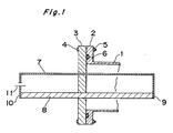
- Fig. 1 a sectional view of the essential portions for illustrating the principle of a cooling apparatus in a first embodiment.
- the vacuum bulkhead 3 is mounted with bolts 4, nuts 5 on the flange 2 of a chamber 1 which becomes vacuum, an 0 ring 6 being interposed in a compressed condition between the flange 2 and the vacuum bulkhead 3, with the gap between them being sealed.
- the first, second thermoelectric materials 7, 8 are made of foreign kinds of materials such as Sb, Bi, with the end portions of the first, second thermoelectric materials 7 and 8 are connected between them to form a circuit.
- the first, second thermoelectric materials 7 and 8 are extended through the vacuum bulkhead 3 and are secured with an epoxide series bonding agent, and also are retained in an airtight condition.
- the cooling portion 9 and the heating portion 10 by a Peltier effect are respectively disposed within the chamber 1 and in the air.
- the DC power supply 11 is inserted halfway thereof in the air into the first thermoelectric material 7. And the cooling portion 9 is connected with the heating supply (not shown).
- the current is fed into a circuit using the first, second thermoelectric materials 7, 8 by a DC power supply 11, and the cooling portion 9 is cooled by the Peltier effect to heat the heating portion 10.
- the heating source may be electronically cooled by the cooling operation of the cooling portion 9. At this time, there is less in convection current in the vacuum, so that the cooling efficiency of the heating source by the cooling portion 9 may be improved.
- the cooling operation is electronically effected as described hereinabove, the response speed of the cooling may be improved as compared with the water cooling system or the like in the conventional embodiment.
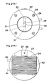
- Fig. 2 (a) through (c) show the cooling apparatus in the second embodiment.
- Fig. 2 (a) shows the sectional view of the essential portions.
- Fig. 2 (b) is an arrow view taken along the IIb - IIb of the (a) thereof.
- Fig. 2 (c) is a left side view of the (a) thereof.
- the vacuum bulkhead 23 is mounted with bolts 24, nuts 25 on the flange 22 of the chamber 21 which becomes vacuum, and an 0 ring 26 is interposed in a compressed condition between the flange 22 and the vacuum bulkhead 23, with the gap between them being sealed.
- the first, second thermoelectric materials 27, 28 are formed linear of semiconductors of, for example, Bi 2 Te 3 + Sb 2 Te 3 , Bi 2 Te 3 + Bi 2 Se 3 . And preferably they are covered with metallic sheaths.
- An electronic plate 29 made of Cu is spliced by solder of an In radical between one-end portions of the first, second thermoelectric materials 27, 28, and the electrode plates 30, 31 made of Cu are spliced by solder of an In radical with the respective other ends of the first, second thermoelectric materials 27, 28, so that the Cu line 32 is taken out from the electrode plates 30, 31 to form the circuit.
- the splicing portion between the first, second thermoelectric materials 27, 28 and the electrode plate 29 becomes a cooling portion 33 by the Peltier effect, and the splicing portion between the first, second thermoelectric materials 27, 28 and the electrode plates 30, 31 is set to become a heating portion 34.
- the first, second thermoelectric materials 27, 28 are extended through the vacuum bulkhead 23, are secured with an epoxide series bonding agent and also, are retained in air tight condition, so that the cooling portion 33 and the heating portion 34 are respectively disposed within the chamber 21 and in the air.
- a DC power supply 35 is inserted halfway of the Cu line 32 taken out from the electrode plates 30, 31 constituting the heating portion 34.
- a cooling block 36 for cooling these heating portions 34, 34 is provided across between the heating portions 34, 34. Namely, one side of the stay 37 is mounted on one side of the cooling block 36, the other side of the stay 37 is mounted on the vacuum bulkhead 23 from the bolt 38.
- the cooling block 36 is supported with respect to the vacuum bulkhead 23 and is retained in contact condition with the heating portions 34, 34.
- the cooling block 36 has therein a cooling chamber 39, with which the respective one end of the circulating pipes 40, 41 of the cooling medium are communicated, with the other ends of the respective circulating pipes 40, 41 being communicated with a pump (not shown).
- An air cooling fin 42 is mounted on the outer face of the cooling block 36. And the cooling portion 33 is connected with the heating source (not shown).
- the cooling portion 33 When a current is fed into a circuit using the first, second thermoelectric materials 27, 28 by the DC current supply 35, the cooling portion 33 is cooled by the Peltier effect, and the heating portion 34 is heated. And the heating source may be electronically cooled by the cooling of the cooling portion 33. At this time, as there is no convention currents in the vacuum, the cooling efficiency of the heating source may be improved by the cooling portion 33.
- the cooling water is circulated into the circulating pipe 40, the cooling room 39 of the cooling block 36, the circulating pipe 41 by the driving operation of the pump so as to cool the heating portion together with air cooling fin 42 by the cooling block 36, so that the transferring of the heat of the heating portion 34 into the cooling operation 33 by the first, second thermoelectric materials 27, 28 may be reduced so as to improve the cooling efficiency all the more.
- the electronic cooling operation is effected as described hereinabove, the response speed of the cooling operation may be improved as compared with the conventional water cooling system or the like.
- the first, second thermoelectric materials 27, 28 are made linear as described hereinabove, also, the first, second linear thermoelectric materials 27, 28 are covered with all the sheaths.
- the cooling portion 33 may be easily connected with the heating source by the use of the flexibility thereof.
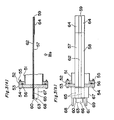
- FIG. 3 (a), (b) show the cooling apparatus in an embodiment of the present invention, with the (a) thereof being the sectional view of the essential portions, the (b) thereof being the IIIb arrow view of the (a) thereof.
- the vacuum bulkhead 53 is mounted with bolts 54 and nuts 55 on the flange 52 of the chamber 51 which becomes vacuum, and an 0 ring 56 is interposed in a compression condition between the flange 52 and the vacuum bulkhead 53, with the position between them being sealed.
- the first, second thermoelectric materials 57, 58 are in thin membrane shape together with the electrodes 59, 60, 61 on the thin basic plate 62 by, for example, Bi 2 Te 3 + Sb 2 Te 3 , Bi 2 Te 3 + Bi 2 Se 3 .
- the electrode 59 is provided by the vacuum evaporation or the like on one side end portion on the basic plate 62 made of the epoxide resin, glass or the like, a pair of electrodes 60, 61 are respectively provided along the long side on the other side end portion by the vacuum evaporation or the like.
- the first, second thermoelectric materials 57, 58 are provided by the vacuum evaporation or the like along the long side of the basic plate 62 on the basic plate 62 and the electrodes 59, 60, 61.
- the basic plate 61 is made of a deformable material, with the first, second thermoelectric materials 57, 58, the basic plate 62 or the like are composed to be freely deformable.
- the Cu line 63 is taken out from the electrodes 60, 61 to form a circuit. And the splicing portion between the first, second thermoelectric materials 57, 58 and the electrode 59 becomes a cooling portion 64, with the splicing portions between the first, second thermoelectric materials 57, 58 and the electrode plates 60, 61 are set to become the heating portion 65.
- the first, second thermoelectric material 57, 58 are extended through the vacuum bulkhead 53 and are secured with the epoxide series bonding agent, and also, are retained in the airtight condition, so that the cooling portion 64 and the heating portion 65 are respectively disposed within the chamber 51 and in the air.
- a DC power supply 66 is inserted halfway of the Cu line 63 which is taken out from the electrode plates 60, 61 constituting the heating portion 65.
- the cooling block 67 for cooling the heating portions 65, 65 is provided across the heating portions 65, 65.
- the cooling block 67 has a cooling room therein as in the second embodiment, with the respective one-ends of the circulating pipes 68, 69 being communicated with the cooling chamber, the other ends of the respective circulating pipes 68, 69 being communicated with the pump (not shown).
- the cooling portion 64 is connected with the heating source (not shown).
- the cooling portion 64 When the current is fed into the circuit using the first, second thermoelectric materials 57, 58 by the DC power supply 66, the cooling portion 64 is cooled by the Peltier effect, the heating portion 65 is heated, the heating source may be electronically cooled by the cooling operation of the cooling portion 64. At this time, as there are no convection currents in the vacuum, the cooling efficiency of the heating source by the cooling portion 64 may be improved.
- the cooling operation may be circulated into the circulating pipe 68, the cooling room of the cooling block 67, the circulating pipe 69 by the driving operation of the pump so as to cool the heating portion 65 by the cooling block 67, so that the transferring of the heat of the heating portion 65 into the cooling portion 64 by the first, second thermoelectric materials 57, 58 may be controlled, thus improving the cooling efficiency all the more.
- the cooling operation is electronically effected as described hereinabove, the response speed of the cooling operation may be improved as compared with the conventional water cooling system or the like.
- the first, second thermoelectric materials 57, 58 are provided in a thin membrane shape on the basic plate 62 The cooling portion 64 may be easily connected with the heating source by the use of the flexibility of the basic plate.
- cooling block 67 combined together with the air cooling fin may be used as in the second embodiment.
- liquid nitrogen instead of the cooling water, may- be circulated into the circulating pipes 40, 41, 68, 69, 87, 88 and the cooling blocks 36, 67, 86.
- the cooling operation may be effected to the same temperature as that when the heating source is cooled with the use of liquid helium.
- the heating source is adapted to be electronically cooled by the cooling portion with the Peltier effect disposed in the vacuum by the feeding of the current from the DC power supply into a circuit formed by the use of the thermoelectric materials
- the response speed of the cooling may be improved, also the construction is simplified, the cost may be lowered.
- the pollution within the vacuum portion may be prevented.
- the cooling efficiency of the heating source is improved by the cooling portion.
- the heating portion of the circuit is cooled by the cooling means, so that the transferring operation of the heat of the heating portion to the cooling portion by the thermoelectric material may be reduced, with the cooling efficiency being improved all the more,
Landscapes
- Engineering & Computer Science (AREA)
- Physics & Mathematics (AREA)
- Mechanical Engineering (AREA)
- Thermal Sciences (AREA)
- General Engineering & Computer Science (AREA)
- Thermotherapy And Cooling Therapy Devices (AREA)
- Cooling Or The Like Of Semiconductors Or Solid State Devices (AREA)
- Drying Of Semiconductors (AREA)
- Physical Deposition Of Substances That Are Components Of Semiconductor Devices (AREA)
- Devices That Are Associated With Refrigeration Equipment (AREA)
Claims (9)
- Kühlvorrichtung
mit einem ersten Element, das aus einem ersten thermoelektrischen Material (57) besteht und sich von einer Position innerhalb einer Kammer (51) durch eine Kammerwand (53) nach außerhalb der Kammer erstreckt;
mit einem zweiten Element, das aus einem vom ersten thermoelektrischen Material abweichenden, zweiten Material besteht und sich von einer Position innerhalb der Kammer durch die Kammerwand nach außerhalb der Kammer erstreckt;
mit einer ersten Elektrode (59);
mit einem ersten Verbindungsabschnitt zwischen den ersten und zweiten thermoelektrischen Materialien und der ersten Elektrode (59) zur Bildung eines Kühlabschnittes (64);
mit zweiten Verbindungsabschnitten zwischen dem ersten bzw. dem zweiten thermoelektrischen Materialien und zweiten Elektroden zur Bildung eines Heizabschnittes (65);
wobei der Kühlabschnitt und der Heizabschnitt sich aufeinander entgegengesetzten Seiten der Kammerwand befinden; und
mit einer Gleichstromversorgung, die zur Bildung eines elektrischen Stromkreises elektrisch zwischen die zweiten Elektroden geschaltet ist;
gekennzeichnet durch
eine Grundplatte (62), auf der die ersten und zweiten Elemente als dünne Membranen aus thermoelektrischem Material gebildet sind und sich durch die Kammerwand erstrecken. - Kühlvorrichtung nach Anspruch 1,
dadurch gekennzeichnet, daß das thermoelektrische Material linear ausgebildet ist. - Kühlvorrichtung nach Anspruch 2,
dadurch gekennzeichnet, daß das lineare thermoelektrische Material mit einer metallischen Schicht abgedeckt ist. - Kühlvorrichtung nach Anspruch 1,
dadurch gekennzeichnet, daß das thermoelektrische Material ein Halbleiter ist, der
- Kühlvorrichtung nach einem der Ansprüche 1 bis 4, dadurch gekennzeichnet, daß der Heizabschnitt (65) mit einer Kühlvorrichtung versehen ist.
- Kühlvorrichtung nach Anspruch 5,
dadurch gekennzeichnet, daß die Kühlvorrichtung einen Kühlblock (67) mit einem Kühlraum sowie ein Zirkulationsrohr (68, 69) mit einem Kühlmedium aufweist, das mit dem Kühlraum des Kühlblockes (67) kommuniziert. - Kühlvorrichtung nach Anspruch 5,
dadurch gekennzeichnet, daß die Kühlvorrichtung ein Luftkühlkörper (42) ist. - Kühlvorrichtung nach Anspruch 5,
dadurch gekennzeichnet, daß die Kühlvorrichtung einen Kühlblock (67) mit einem Kühlraum sowie ein Zirkulationsrohr (68, 69) mit einem Kühlmedium aufweist, das mit dem Kühlraum des Kühlblockes (67) kommuniziert, und daß auf dem Kühlblock (67) ein Luftkühlkörper montiert ist. - Kühlvorrichtung nach einem der vorstehenden Ansprüche, dadurch gekennzeichnet, daß die Grundplatte (62) aus einem deformierbaren Material besteht.
Applications Claiming Priority (2)
| Application Number | Priority Date | Filing Date | Title |
|---|---|---|---|
| JP192536/88 | 1988-08-01 | ||
| JP63192536A JPH0242720A (ja) | 1988-08-01 | 1988-08-01 | 冷却装置 |
Publications (3)
| Publication Number | Publication Date |
|---|---|
| EP0353671A2 EP0353671A2 (de) | 1990-02-07 |
| EP0353671A3 EP0353671A3 (en) | 1990-04-25 |
| EP0353671B1 true EP0353671B1 (de) | 1992-09-30 |
Family
ID=16292908
Family Applications (1)
| Application Number | Title | Priority Date | Filing Date |
|---|---|---|---|
| EP89114035A Expired - Lifetime EP0353671B1 (de) | 1988-08-01 | 1989-07-29 | Kühlvorrichtung |
Country Status (5)
| Country | Link |
|---|---|
| US (1) | US5070701A (de) |
| EP (1) | EP0353671B1 (de) |
| JP (1) | JPH0242720A (de) |
| KR (1) | KR900003603A (de) |
| DE (1) | DE68903067T2 (de) |
Families Citing this family (6)
| Publication number | Priority date | Publication date | Assignee | Title |
|---|---|---|---|---|
| JP2953273B2 (ja) * | 1993-10-22 | 1999-09-27 | 住友電気工業株式会社 | 低温に冷却する素子の接続方法 |
| JP2642858B2 (ja) * | 1993-12-20 | 1997-08-20 | 日本碍子株式会社 | セラミックスヒーター及び加熱装置 |
| US6333849B1 (en) | 1996-07-01 | 2001-12-25 | Compaq Computer Corporation | Apparatus for liquid cooling of specific computer components |
| FR2767912B1 (fr) * | 1997-09-03 | 2000-02-11 | Joel Camus | Mini cave de cuisine a double enceintes |
| JP2000031461A (ja) * | 1998-07-09 | 2000-01-28 | Asahi Optical Co Ltd | 半導体デバイスおよび半導体組立装置 |
| JP2010227807A (ja) * | 2009-03-26 | 2010-10-14 | Panasonic Electric Works Co Ltd | 静電霧化装置 |
Family Cites Families (17)
| Publication number | Priority date | Publication date | Assignee | Title |
|---|---|---|---|---|
| FR700013A (fr) * | 1929-11-14 | 1931-02-23 | Appareil frigorifique | |
| FR1205465A (fr) * | 1957-04-16 | 1960-02-03 | Westinghouse Electric Corp | Thermoéléments et appareils dans lesquels ils sont montés |
| GB832422A (en) * | 1957-09-19 | 1960-04-13 | Gen Electric Co Ltd | Improvements in or relating to thermoelectric devices |
| US2994203A (en) * | 1960-01-14 | 1961-08-01 | Westinghouse Electric Corp | Thermoelectric cooling device |
| US3040539A (en) * | 1960-04-27 | 1962-06-26 | Gen Motors Corp | Refrigerating apparatus |
| US3097027A (en) * | 1961-03-21 | 1963-07-09 | Barden Corp | Thermoelectric cooling assembly |
| US3127749A (en) * | 1961-04-13 | 1964-04-07 | Electrolux Ab | Thermoelectric refrigeration |
| US3276914A (en) * | 1962-08-15 | 1966-10-04 | Westinghouse Electric Corp | Reactor-thermoelectric generator |
| US3232063A (en) * | 1964-06-26 | 1966-02-01 | Whirlpool Co | Cooling plate and shelf structure |
| US3648470A (en) * | 1970-05-28 | 1972-03-14 | Gary E Schultz | Materials composition arrangement for thermoelectric heating and cooling |
| US3823567A (en) * | 1973-04-05 | 1974-07-16 | Melbro Corp | Thermoelectric-vacuum shipping container |
| HU170629B (de) * | 1974-01-25 | 1977-07-28 | ||
| FR2274142A1 (fr) * | 1974-06-05 | 1976-01-02 | Couturier G Le | Pompe a chaleur thermo-electrique |
| US4310548A (en) * | 1979-02-01 | 1982-01-12 | Ciba-Geigy Corporation | Pesticidal N-tetrafluorophenyl-N'-benzoyl ureas |
| DE3005112A1 (de) * | 1980-02-12 | 1981-08-20 | Kurt Dipl.-Ing. 6380 Bad Homburg Bojak | Thermoelektrischer generator vorzugsweise fuer wasser-elektrolyse funktionell kombiniert mit waermetauscher-systemen |
| US4593529A (en) * | 1984-12-03 | 1986-06-10 | Birochik Valentine L | Method and apparatus for controlling the temperature and pressure of confined substances |
| DE3639089A1 (de) * | 1986-11-14 | 1988-05-26 | Unitechnica Mobilkaelte Gmbh | Thermoelektrische kuehlvorrichtung |
-
1988
- 1988-08-01 JP JP63192536A patent/JPH0242720A/ja active Pending
-
1989
- 1989-07-29 DE DE8989114035T patent/DE68903067T2/de not_active Expired - Lifetime
- 1989-07-29 EP EP89114035A patent/EP0353671B1/de not_active Expired - Lifetime
- 1989-08-01 US US07/387,969 patent/US5070701A/en not_active Expired - Lifetime
- 1989-08-01 KR KR1019890010972A patent/KR900003603A/ko not_active Ceased
Also Published As
| Publication number | Publication date |
|---|---|
| DE68903067D1 (de) | 1992-11-05 |
| JPH0242720A (ja) | 1990-02-13 |
| US5070701A (en) | 1991-12-10 |
| DE68903067T2 (de) | 1993-02-18 |
| KR900003603A (ko) | 1990-03-26 |
| EP0353671A2 (de) | 1990-02-07 |
| EP0353671A3 (en) | 1990-04-25 |
Similar Documents
| Publication | Publication Date | Title |
|---|---|---|
| US2815472A (en) | Rectifier unit | |
| US6855880B2 (en) | Modular thermoelectric couple and stack | |
| US5349498A (en) | Integral extended surface cooling of power modules | |
| US2780759A (en) | Semiconductor rectifier device | |
| US3635037A (en) | Peltier-effect heat pump | |
| US5167724A (en) | Planar photovoltaic solar concentrator module | |
| US3573569A (en) | Controlled rectifier mounting assembly | |
| US2942165A (en) | Liquid cooled current rectifiers | |
| US4928756A (en) | Heat dissipating fin and method for making fin assembly | |
| EP0353671B1 (de) | Kühlvorrichtung | |
| CN113015400B (zh) | 一种驱动电机功率模块的冷却系统 | |
| EP0892487A1 (de) | Leistungsmodul mit Halbleitern | |
| US2936409A (en) | Current rectifier assemblies | |
| US3411955A (en) | Thermoelectric device | |
| US3183121A (en) | Thermoelectric generator with heat transfer and thermal expansion adaptor | |
| US20060262819A1 (en) | Diode laser component with an integrated cooling element | |
| US3715632A (en) | Liquid cooled semiconductor device clamping assembly | |
| JP3062754B1 (ja) | 熱電発電モジュ―ル | |
| US4354272A (en) | Solid crystal laser emission device with an improved external cooling circuit | |
| JP3404841B2 (ja) | 熱電変換装置 | |
| US3303058A (en) | Thermoelectric module | |
| JPS57147257A (en) | Cooler | |
| JPH02271683A (ja) | 熱電素子および熱電素子の製造方法 | |
| SU1414235A1 (ru) | Полупроводниковый блок | |
| JPH01214073A (ja) | 熱電気変換装置 |
Legal Events
| Date | Code | Title | Description |
|---|---|---|---|
| PUAI | Public reference made under article 153(3) epc to a published international application that has entered the european phase |
Free format text: ORIGINAL CODE: 0009012 |
|
| 17P | Request for examination filed |
Effective date: 19890729 |
|
| AK | Designated contracting states |
Kind code of ref document: A2 Designated state(s): DE FR GB |
|
| PUAL | Search report despatched |
Free format text: ORIGINAL CODE: 0009013 |
|
| AK | Designated contracting states |
Kind code of ref document: A3 Designated state(s): DE FR GB |
|
| 17Q | First examination report despatched |
Effective date: 19910115 |
|
| GRAA | (expected) grant |
Free format text: ORIGINAL CODE: 0009210 |
|
| AK | Designated contracting states |
Kind code of ref document: B1 Designated state(s): DE FR GB |
|
| REF | Corresponds to: |
Ref document number: 68903067 Country of ref document: DE Date of ref document: 19921105 |
|
| ET | Fr: translation filed | ||
| PLBE | No opposition filed within time limit |
Free format text: ORIGINAL CODE: 0009261 |
|
| STAA | Information on the status of an ep patent application or granted ep patent |
Free format text: STATUS: NO OPPOSITION FILED WITHIN TIME LIMIT |
|
| 26N | No opposition filed | ||
| REG | Reference to a national code |
Ref country code: GB Ref legal event code: IF02 |
|
| PGFP | Annual fee paid to national office [announced via postgrant information from national office to epo] |
Ref country code: DE Payment date: 20080814 Year of fee payment: 20 |
|
| PGFP | Annual fee paid to national office [announced via postgrant information from national office to epo] |
Ref country code: FR Payment date: 20080718 Year of fee payment: 20 |
|
| PGFP | Annual fee paid to national office [announced via postgrant information from national office to epo] |
Ref country code: GB Payment date: 20080806 Year of fee payment: 20 |
|
| REG | Reference to a national code |
Ref country code: GB Ref legal event code: PE20 Expiry date: 20090728 |
|
| PG25 | Lapsed in a contracting state [announced via postgrant information from national office to epo] |
Ref country code: GB Free format text: LAPSE BECAUSE OF EXPIRATION OF PROTECTION Effective date: 20090728 |