EP0353635B1 - Fluid pressure controller for antilock brake control device - Google Patents
Fluid pressure controller for antilock brake control device Download PDFInfo
- Publication number
- EP0353635B1 EP0353635B1 EP89113884A EP89113884A EP0353635B1 EP 0353635 B1 EP0353635 B1 EP 0353635B1 EP 89113884 A EP89113884 A EP 89113884A EP 89113884 A EP89113884 A EP 89113884A EP 0353635 B1 EP0353635 B1 EP 0353635B1
- Authority
- EP
- European Patent Office
- Prior art keywords
- spool
- flow
- passage
- outlet port
- inlet port
- Prior art date
- Legal status (The legal status is an assumption and is not a legal conclusion. Google has not performed a legal analysis and makes no representation as to the accuracy of the status listed.)
- Expired - Lifetime
Links
Images

Classifications
-
- B—PERFORMING OPERATIONS; TRANSPORTING
- B60—VEHICLES IN GENERAL
- B60T—VEHICLE BRAKE CONTROL SYSTEMS OR PARTS THEREOF; BRAKE CONTROL SYSTEMS OR PARTS THEREOF, IN GENERAL; ARRANGEMENT OF BRAKING ELEMENTS ON VEHICLES IN GENERAL; PORTABLE DEVICES FOR PREVENTING UNWANTED MOVEMENT OF VEHICLES; VEHICLE MODIFICATIONS TO FACILITATE COOLING OF BRAKES
- B60T15/00—Construction arrangement, or operation of valves incorporated in power brake systems and not covered by groups B60T11/00 or B60T13/00
-
- B—PERFORMING OPERATIONS; TRANSPORTING
- B60—VEHICLES IN GENERAL
- B60T—VEHICLE BRAKE CONTROL SYSTEMS OR PARTS THEREOF; BRAKE CONTROL SYSTEMS OR PARTS THEREOF, IN GENERAL; ARRANGEMENT OF BRAKING ELEMENTS ON VEHICLES IN GENERAL; PORTABLE DEVICES FOR PREVENTING UNWANTED MOVEMENT OF VEHICLES; VEHICLE MODIFICATIONS TO FACILITATE COOLING OF BRAKES
- B60T8/00—Arrangements for adjusting wheel-braking force to meet varying vehicular or ground-surface conditions, e.g. limiting or varying distribution of braking force
- B60T8/32—Arrangements for adjusting wheel-braking force to meet varying vehicular or ground-surface conditions, e.g. limiting or varying distribution of braking force responsive to a speed condition, e.g. acceleration or deceleration
- B60T8/88—Arrangements for adjusting wheel-braking force to meet varying vehicular or ground-surface conditions, e.g. limiting or varying distribution of braking force responsive to a speed condition, e.g. acceleration or deceleration with failure responsive means, i.e. means for detecting and indicating faulty operation of the speed responsive control means
- B60T8/92—Arrangements for adjusting wheel-braking force to meet varying vehicular or ground-surface conditions, e.g. limiting or varying distribution of braking force responsive to a speed condition, e.g. acceleration or deceleration with failure responsive means, i.e. means for detecting and indicating faulty operation of the speed responsive control means automatically taking corrective action
- B60T8/94—Arrangements for adjusting wheel-braking force to meet varying vehicular or ground-surface conditions, e.g. limiting or varying distribution of braking force responsive to a speed condition, e.g. acceleration or deceleration with failure responsive means, i.e. means for detecting and indicating faulty operation of the speed responsive control means automatically taking corrective action on a fluid pressure regulator
-
- B—PERFORMING OPERATIONS; TRANSPORTING
- B60—VEHICLES IN GENERAL
- B60T—VEHICLE BRAKE CONTROL SYSTEMS OR PARTS THEREOF; BRAKE CONTROL SYSTEMS OR PARTS THEREOF, IN GENERAL; ARRANGEMENT OF BRAKING ELEMENTS ON VEHICLES IN GENERAL; PORTABLE DEVICES FOR PREVENTING UNWANTED MOVEMENT OF VEHICLES; VEHICLE MODIFICATIONS TO FACILITATE COOLING OF BRAKES
- B60T8/00—Arrangements for adjusting wheel-braking force to meet varying vehicular or ground-surface conditions, e.g. limiting or varying distribution of braking force
- B60T8/32—Arrangements for adjusting wheel-braking force to meet varying vehicular or ground-surface conditions, e.g. limiting or varying distribution of braking force responsive to a speed condition, e.g. acceleration or deceleration
- B60T8/34—Arrangements for adjusting wheel-braking force to meet varying vehicular or ground-surface conditions, e.g. limiting or varying distribution of braking force responsive to a speed condition, e.g. acceleration or deceleration having a fluid pressure regulator responsive to a speed condition
- B60T8/40—Arrangements for adjusting wheel-braking force to meet varying vehicular or ground-surface conditions, e.g. limiting or varying distribution of braking force responsive to a speed condition, e.g. acceleration or deceleration having a fluid pressure regulator responsive to a speed condition comprising an additional fluid circuit including fluid pressurising means for modifying the pressure of the braking fluid, e.g. including wheel driven pumps for detecting a speed condition, or pumps which are controlled by means independent of the braking system
-
- B—PERFORMING OPERATIONS; TRANSPORTING
- B60—VEHICLES IN GENERAL
- B60T—VEHICLE BRAKE CONTROL SYSTEMS OR PARTS THEREOF; BRAKE CONTROL SYSTEMS OR PARTS THEREOF, IN GENERAL; ARRANGEMENT OF BRAKING ELEMENTS ON VEHICLES IN GENERAL; PORTABLE DEVICES FOR PREVENTING UNWANTED MOVEMENT OF VEHICLES; VEHICLE MODIFICATIONS TO FACILITATE COOLING OF BRAKES
- B60T8/00—Arrangements for adjusting wheel-braking force to meet varying vehicular or ground-surface conditions, e.g. limiting or varying distribution of braking force
- B60T8/32—Arrangements for adjusting wheel-braking force to meet varying vehicular or ground-surface conditions, e.g. limiting or varying distribution of braking force responsive to a speed condition, e.g. acceleration or deceleration
- B60T8/34—Arrangements for adjusting wheel-braking force to meet varying vehicular or ground-surface conditions, e.g. limiting or varying distribution of braking force responsive to a speed condition, e.g. acceleration or deceleration having a fluid pressure regulator responsive to a speed condition
- B60T8/50—Arrangements for adjusting wheel-braking force to meet varying vehicular or ground-surface conditions, e.g. limiting or varying distribution of braking force responsive to a speed condition, e.g. acceleration or deceleration having a fluid pressure regulator responsive to a speed condition having means for controlling the rate at which pressure is reapplied to or released from the brake
- B60T8/5018—Pressure reapplication using restrictions
- B60T8/5025—Pressure reapplication using restrictions in hydraulic brake systems
- B60T8/5037—Pressure reapplication using restrictions in hydraulic brake systems closed systems
Definitions
- the present invention relates to a fluid pressure controller for use in an antilock brake control device for a motor vehicle and having a flow changeover valve for controlling the braking pressure.
- a flow changeover valve 3 is employed to increase the braking pressure in a controlled manner in place of a solenoid valve as used in the former Publication.
- This flow changeover valve 3 comprises a housing 31 formed with an inlet port 31a communicating with a master cylinder 2, an outlet port 31b communicating with a wheel brake 4 and a discharge port 31c communicating with a solenoid valve 5 serving as a discharge valve, and a spool 32 slidably mounted in the housing 31 and biased by a spring 34 to open and close fluid communication among these ports.
- a large-flow channel is formed extending from the inlet port 31a to the outlet port 31b through a peripheral groove 32a formed in the outer periphery of the spool 32.
- the solenoid valve 5 When the solenoid valve 5 is energized and opened in the antilock control, hydraulic oil will be discharged through the discharge port 31c into a reservoir 63. This will move the spool 32 to the position shown in Fig. 4B owing to a difference of pressures on both ends thereof. In this state, the abovementioned large-flow channel is closed by an edge 32b on the spool 32.
- the spool 32 will further move to the position shown in Fig. 4C where part,of the peripheral groove 32a at the side of an edge 32c opens to a passageway 31e.
- a discharge channel is formed from the outlet port 31b to the discharge port 31c through the groove 32a and the passageway 31e, allowing hydraulic oil in the wheel brake 4 to be discharged into the reservoir 63 through the solenoid valve 5 to reduce the braking pressure.
- the hydraulic oil discharged is sucked and pressurized by a pump 61 driven by a motor 62 so as to be returned to the line between the master cylinder 2 and the inlet port 31a.
- the spool 32 When the solenoid valve 5 is deactivated in the state shown in Fig. 4C to increase the braking pressure, the spool 32 will perform metering action at its edge 32d, forming a restricted-flow channel connecting the inlet port 31a with the outlet port 31b through a passage 31d, an orifice 33, a pressure reducing chamber 36, the passage 31e and the annular groove 32a. The wheel braking pressure will rise slowly. When the pressure difference between the inlet port 31a and the outlet port 31b reduces to a certain level, the spool 32 will return to its original positon shown in Fig. 4A.
- the flow rate of hydraulic oil through the orifice 33 is determined by the pressure difference at both ends thereof which is in turn determined by the effective sectional area of the spool 32 and the biasing force of the spring 34.
- the pressure difference at both ends of the orifice 33 can be limited to a minimum. This will not only serve to keep constant the flow rate through the orifice irrespective of the pressure difference between the inlet port 31a and the outlet port 31b, but also make it possible to reduce the flow rate through the orifice even if it has a rather large diameter.
- this system will be advantageously applied to a compact car having a small-sized brake which has to be controlled with a small amount of hydraulic oil.
- the spool when the braking pressure is being reduced for antilock control, the spool is adapted to move to such a position as to bring the inlet 31a and the outlet 31b into communication with each other as shown in Fig. 4B and further move to the positon shown in Fig. 4C, where the outlet port 31b is brought into communication with the discharge port 31c.
- the spool will move to open the restricted-flow channel through the orifice. If the spool is in a position between the position shown in Fig. 4B and the position shown in Fig. 4C, both the large-flow channel as well as the restricted-flow channel are closed up by the edge 32b and the 32c, respectively. If the spool should get stuck in this position owing to rust or foreign matter, it will become impossible to increase the braking pressure to the wheel brake 4 by increasing the pressure in the master cylinder 2.
- a pressure control valve according to the preamble part of the claim 1 is known from US-A-3 856 047.
- This control valve shows a flapper valve controlled by a solenoid.
- this flapper valve it is not possible, to allow a fluid flow from the inlet port to the outlet port of the valve and thereby to prohibit a fluid flow in the reverse direction.
- An object of the present invention is to provide a fluid pressure controller for antilock brake control which obviates the abovesaid shortcomings.
- a fluid pressure controller for use in an antilock brake control device for a motor vehicle having a master cylinder and a wheel brake, the controller having a flow rate changeover valve comprising: a housing formed with an inlet port communicating with the master cylinder and an outlet port communicating with the wheel brake; a spool slidably mounted in the housing and formed with a passage and an orifice for changing over the communication between the inlet port and the outlet port; the spool being moved under fluid pressure between a first position where a large-flow passage is formed between the inlet port and the outlet port and a second position where a restricted-flow passage through the orifice is formed between the inlet port and the outlet port with the large-flow passage blocked; and a check valve provided in a passage in parallel with the restricted-flow passage and adapted to allow a fluid flow from the inlet port toward the outlet port to pass even if both of the large-flow passage and the restricted-flow passage are blocked.
- hydraulic oil can be supplied through a check valve in the passage provided in parallel with the restricted-flow channel formed between the housing and the sleeve into the wheel brake to increase the braking pressure.
- the check valve serves to permit the fluid flow from the inlet toward the outlet but not the flow in a reverse direction.
- the braking pressure can be reduced by reducing the pressure in the master cylinder and thus the inlet pressure even if the spool gets stuck.
- the pressure at the inlet pressure in the master cylinder
- the pressure at the outlet braking pressure
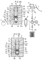
- Figs. 1A to 1C show the first embodiment which differs from the prior art controller shown in Fig. 4A in that the housing 31 is formed with a passage 31g and that a check valve 37 comprising a ball and a fixed valve seat 31h is provided in the passage 31g, which extends in parallel with the restricted-flow channel.
- this valve operates in the same way as the prior art valve shown in Fig. 4A. Namely, while the valve is in the position shown in Fig. 1, where the antilock control is not activated, hydraulic oil does not flow through the orifice 33 but flows through the large-flow channel. The pressures at both sides of the check valve 37 are kept equal.
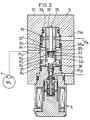
- Figs. 2A and 2B show the second embodiment which employs a flow rate changeover valve 3 of a different type from that of the first embodiment. Other parts are identical to those used in the first embodiment.
- the flow rate changeover valve 3 comprises a housing 31 formed with an inlet port 31a communicating with the master cylinder 2, a port P01 communicating with the wheel brake 4 and a port P02 communicating with the discharge line, and a spool 32 formed with channels for fluid communication and slidably mounted in the housing 31 so that the communications among the ports can be changed over.
- the spool 32 is biased by a spring 34 in one direction.
- This flow rate changeover valve 3 is formed in its housing 31 with channels R3 and R4 and provided in the lines leading from the respective channels R3 and R4 to the wheel brake 4 with check valves 37 and 37′, respectively, to assure reliable braking in case of emergency. In normal conditions, whether in the antilock control mode or not, these circuits are kept inoperative.
- a large-flow channel is formed extending from the inlet port 31a to the outlet port P01 through a passage P1, a pressure application chamber 35 and passages P2 and R1.
- the solenoid 5 is activated to open it and discharge hydraulic oil into the discharge line through the discharge port P02.
- the pressure in the pressure reducing chamber 6 will drop, creating a pressure difference between the chamber 6 and the pressure application chamber 35.
- This pressure difference will move the spool 32 to such a position that the large-flow channel is closed by its edge portion 32b.
- the edge 32c will be opened to form a channel connecting the outlet port P01 to the discharge port P02.
- the fluid pressure on the wheel brake 4 will drop.
- the inlet and outlet ports formed in the housing 31 and the passages formed in the spool 32 are arranged so that when the outlet P01 is shut off from the passage P2 by the edge portion 32b, the inlet port 31a communicates with the passage P1 while keeping the passage P3 out of communication with the outlet port P01, and so that when the spool 32 further descends to the position shown in Fig. 2B, the passage P3 communcates with the outlet port P01 and the inlet port 31a and the passage P1 communicate with each other through a small gap.
- the relative positions of the parts are determined so that the spool 32 will stop at this position with a balance established between the biassing force of the spring 34 and the force urging the spool 32 downwardly.
- the spool 32 should stick to the housing 31 and get immovable during antilock control at such a position that the edge portions 32b and 32c close the large-flow channel extending through the passages P2 and R1 in the spool 32 and the restricted-flow channel extending through the passage P3 and R2, no braking pressure can be supplied to the wheel brake through either of the above two channels.
- the passage R4 branches off from the wide channel in parallel with the edge 32c adapted to close the narrow channel and the check valve 37 is provided in the line connecting the passage R4 with the wheel brake 4.
- the solenoid valve 5 is supposed to be closed in such an emergency situation.
- the hydraulic oil in the wheel brake 4 will return to the master cylinder 5 through the other check valve 37', the passage R3 and the inlet port 31a.
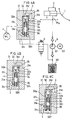
- Fig. 3 shows only a flow rate changeover valve 3 for simplification. It has essentially the same construction as the valve in the second embodiment (Fig. 2A) and differs therefrom only in that a sleeve 38 is provided between the housing 31 and the spool 32, that the solenoid valve 5 is integral with the valve 3, and that check valves have a different construction from those in the second embodiment. The function of check valves is completely the same as with the second embodiment.
- cup seals which serve as the check valves 37 and 37' are fitted in annular grooves formed in the outer periphery of the sleeve 38.
- Other annular grooves R0 and R4 serve as channels for the check valves 37 and 37′.
Landscapes
- Engineering & Computer Science (AREA)
- Physics & Mathematics (AREA)
- Fluid Mechanics (AREA)
- Transportation (AREA)
- Mechanical Engineering (AREA)
- Regulating Braking Force (AREA)
Description
- The present invention relates to a fluid pressure controller for use in an antilock brake control device for a motor vehicle and having a flow changeover valve for controlling the braking pressure.
- With the spread of antilock brake control devices for motor vehicles, it is becoming an urgent requirement to develop an antilock control device applicable to a compact economy car. To meet this requirement, it was proposed in GB-A-8512610 to use a single solenoid valve for each vehicle wheel and control with two control modes, i.e. pressure reduction and pressure increase, instead of using two solenoid valves for each vehicle wheel as disclosed in Japanese Examined Patent Publication 49-28307.
- The device disclosed in the latter Publication is shown in Figs. 4A, 4B and 4C in which a
flow changeover valve 3 is employed to increase the braking pressure in a controlled manner in place of a solenoid valve as used in the former Publication. Thisflow changeover valve 3 comprises ahousing 31 formed with aninlet port 31a communicating with amaster cylinder 2, anoutlet port 31b communicating with awheel brake 4 and adischarge port 31c communicating with asolenoid valve 5 serving as a discharge valve, and aspool 32 slidably mounted in thehousing 31 and biased by aspring 34 to open and close fluid communication among these ports. - When the
valve 3 is in its original position shown in Fig. 4A, where the antilock control is not in action, a large-flow channel is formed extending from theinlet port 31a to theoutlet port 31b through aperipheral groove 32a formed in the outer periphery of thespool 32. When thesolenoid valve 5 is energized and opened in the antilock control, hydraulic oil will be discharged through thedischarge port 31c into areservoir 63. This will move thespool 32 to the position shown in Fig. 4B owing to a difference of pressures on both ends thereof. In this state, the abovementioned large-flow channel is closed by anedge 32b on thespool 32. - The
spool 32 will further move to the position shown in Fig. 4C where part,of theperipheral groove 32a at the side of anedge 32c opens to apassageway 31e. Thus a discharge channel is formed from theoutlet port 31b to thedischarge port 31c through thegroove 32a and thepassageway 31e, allowing hydraulic oil in thewheel brake 4 to be discharged into thereservoir 63 through thesolenoid valve 5 to reduce the braking pressure. The hydraulic oil discharged is sucked and pressurized by apump 61 driven by amotor 62 so as to be returned to the line between themaster cylinder 2 and theinlet port 31a. - When the
solenoid valve 5 is deactivated in the state shown in Fig. 4C to increase the braking pressure, thespool 32 will perform metering action at itsedge 32d, forming a restricted-flow channel connecting theinlet port 31a with theoutlet port 31b through apassage 31d, anorifice 33, apressure reducing chamber 36, thepassage 31e and theannular groove 32a. The wheel braking pressure will rise slowly. When the pressure difference between theinlet port 31a and theoutlet port 31b reduces to a certain level, thespool 32 will return to its original positon shown in Fig. 4A. - This arrangement is economical because each wheel can be controlled with a single solenoid valve. The flow rate of hydraulic oil through the
orifice 33 is determined by the pressure difference at both ends thereof which is in turn determined by the effective sectional area of thespool 32 and the biasing force of thespring 34. When the pressure difference increases above the biasing force of thespring 34, thespool 32 will be moved to close the restricted-flow channel with itsmetering edge 32d. Thus the pressure difference at both ends of theorifice 33 can be limited to a minimum. This will not only serve to keep constant the flow rate through the orifice irrespective of the pressure difference between theinlet port 31a and theoutlet port 31b, but also make it possible to reduce the flow rate through the orifice even if it has a rather large diameter. Thus this system will be advantageously applied to a compact car having a small-sized brake which has to be controlled with a small amount of hydraulic oil. - With this type of flow rate changeover valve, when the braking pressure is being reduced for antilock control, the spool is adapted to move to such a position as to bring the
inlet 31a and theoutlet 31b into communication with each other as shown in Fig. 4B and further move to the positon shown in Fig. 4C, where theoutlet port 31b is brought into communication with thedischarge port 31c. When increasing the braking pressure again in this state, the spool will move to open the restricted-flow channel through the orifice. If the spool is in a position between the position shown in Fig. 4B and the position shown in Fig. 4C, both the large-flow channel as well as the restricted-flow channel are closed up by theedge 32b and the 32c, respectively. If the spool should get stuck in this position owing to rust or foreign matter, it will become impossible to increase the braking pressure to thewheel brake 4 by increasing the pressure in themaster cylinder 2. - This problem is not peculiar to a system having such a prior art flow rate changeover valve of the above-described type but is a common problem with any system having a spool adapted to shut off communication between an inlet and an outlet when it is in a position between its original position where a large-flow channel is formed between the inlet and the outlet and a position where a restricted-flow channel is formed to increase the braking pressure again.
- A pressure control valve according to the preamble part of the claim 1 is known from US-A-3 856 047. This control valve shows a flapper valve controlled by a solenoid. However, with this flapper valve it is not possible, to allow a fluid flow from the inlet port to the outlet port of the valve and thereby to prohibit a fluid flow in the reverse direction.
- An object of the present invention is to provide a fluid pressure controller for antilock brake control which obviates the abovesaid shortcomings.
- In accordance with the present invention, there is provided a fluid pressure controller for use in an antilock brake control device for a motor vehicle having a master cylinder and a wheel brake, the controller having a flow rate changeover valve comprising: a housing formed with an inlet port communicating with the master cylinder and an outlet port communicating with the wheel brake; a spool slidably mounted in the housing and formed with a passage and an orifice for changing over the communication between the inlet port and the outlet port; the spool being moved under fluid pressure between a first position where a large-flow passage is formed between the inlet port and the outlet port and a second position where a restricted-flow passage through the orifice is formed between the inlet port and the outlet port with the large-flow passage blocked; and a check valve provided in a passage in parallel with the restricted-flow passage and adapted to allow a fluid flow from the inlet port toward the outlet port to pass even if both of the large-flow passage and the restricted-flow passage are blocked.
- According to the present invention, if the spool should get stuck at a position between its original position and the position for increasing the braking pressure again, hydraulic oil can be supplied through a check valve in the passage provided in parallel with the restricted-flow channel formed between the housing and the sleeve into the wheel brake to increase the braking pressure. The check valve serves to permit the fluid flow from the inlet toward the outlet but not the flow in a reverse direction.
- During normal conditions, when the spool is free to slide, the time during which both the large-flow and restricted-flow channels are closed is so short that the check valve will not have any bad effect.
- Also, by the provision of the check valve, the braking pressure can be reduced by reducing the pressure in the master cylinder and thus the inlet pressure even if the spool gets stuck. In normal conditions, the pressure at the inlet (pressure in the master cylinder) is always lower than the pressure at the outlet (braking pressure) and thus the check valve will not have any bad effect.
- According to the present invention, even if the spool should get locked, at least minimum braking pressure required to ensure safety can be applied to the wheel brakes.
- Other features and objects of the present invention will become apparent from the following description taken with reference to the accompanying drawings, in which:
- Figs. 1A - 1C are schematic views of the first embodiment in different conditions;
- Figs. 2A and 2B are schematic views of the second embodiment in different conditions;
- Fig. 3 is a schematic view of the third embodiment; and
- Figs. 4A - 4C are schematic views of a prior art fluid pressure controller in different conditions.
- Figs. 1A to 1C show the first embodiment which differs from the prior art controller shown in Fig. 4A in that the
housing 31 is formed with apassage 31g and that acheck valve 37 comprising a ball and afixed valve seat 31h is provided in thepassage 31g, which extends in parallel with the restricted-flow channel. In normal conditions, this valve operates in the same way as the prior art valve shown in Fig. 4A. Namely, while the valve is in the position shown in Fig. 1, where the antilock control is not activated, hydraulic oil does not flow through theorifice 33 but flows through the large-flow channel. The pressures at both sides of thecheck valve 37 are kept equal. - During the pressure reduction phase of antilock control, hydraulic oil will be discharged through the
discharge port 31c. Thus the pressure in thepressure reducing chamber 36 and thepassage 31f will drop and the ball of the check valve will be pressed against thevalve seat 31h. This state continues until theedge 32c is opened. When thespool 32 moves to the position shown in Fig. 1C, hydraulic oil will flow through theoutlet port 31b, thegroove 32a formed in the outer periphery of thespool 32,edge 32c andpassage 31e so as to be discharged through thedischarge port 31c. Now the pressures at both sides of thecheck valve 37 will become equal again. - If the
spool 32 should get stuck in a position between the position shown in Fig. 1B and the position shown in Fig. 1C, though the restricted-flow channel extending from theinlet port 31a to theoutlet port 31b throughpassage 31d,orifice 33,pressure reducing chamber 34,passage 31f andperipheral groove 32a is shut off by theedge portion 32c, hydraulic oil can flow through thepassage 31g, pushing up thecheck valve 37, and to theoutlet port 31b to apply pressure to thewheel brake 4. - Figs. 2A and 2B show the second embodiment which employs a flow
rate changeover valve 3 of a different type from that of the first embodiment. Other parts are identical to those used in the first embodiment. - In this embodiment, the flow
rate changeover valve 3 comprises ahousing 31 formed with aninlet port 31a communicating with themaster cylinder 2, a port P01 communicating with thewheel brake 4 and a port P02 communicating with the discharge line, and aspool 32 formed with channels for fluid communication and slidably mounted in thehousing 31 so that the communications among the ports can be changed over. Thespool 32 is biased by aspring 34 in one direction. - This flow
rate changeover valve 3 is formed in itshousing 31 with channels R3 and R4 and provided in the lines leading from the respective channels R3 and R4 to thewheel brake 4 withcheck valves - In the state shown in Fig. 2A, where the antilock control is not in action, a large-flow channel is formed extending from the
inlet port 31a to the outlet port P01 through a passage P1, apressure application chamber 35 and passages P2 and R1. To reduce the braking pressure during antilock control, thesolenoid 5 is activated to open it and discharge hydraulic oil into the discharge line through the discharge port P02. As a result, the pressure in thepressure reducing chamber 6 will drop, creating a pressure difference between thechamber 6 and thepressure application chamber 35. This pressure difference will move thespool 32 to such a position that the large-flow channel is closed by itsedge portion 32b. When thespool 32 further moves to the position shown in Fig. 2B, theedge 32c will be opened to form a channel connecting the outlet port P01 to the discharge port P02. The fluid pressure on thewheel brake 4 will drop. - When increasing the braking pressure again during antilock control, the
solenoid valve 5 is turned off to close it. Thespool 32 will remain in the position shown in Fig. 2B to perform metering action at itsedge portion 32d. Thus a restricted-flow channel will be formed extending from theinlet port 31a to the outlet port P01 through passage P1,pressure application chamber 35,orifice 33,pressure reducing chamber 36 and passages P3 and R2. Owing to the pressure difference at both ends of theorifice 33, which is determined by the effective sectional area of thespool 32 and the biasing force of thespring 34, hydraulic oil will flow at a low rate through theorifice 33. When the braking pressure increases to such a level that the pressure difference between theinlet port 31a and the outlet port P01 falls below the pressure difference at both ends of theorifice 33, thespool 32 will be pushed up by thespring 34 to return to the position shown in Fig. 2A, where the large-flow channel opens again. - The inlet and outlet ports formed in the
housing 31 and the passages formed in thespool 32 are arranged so that when the outlet P01 is shut off from the passage P2 by theedge portion 32b, theinlet port 31a communicates with the passage P1 while keeping the passage P3 out of communication with the outlet port P01, and so that when thespool 32 further descends to the position shown in Fig. 2B, the passage P3 communcates with the outlet port P01 and theinlet port 31a and the passage P1 communicate with each other through a small gap. The relative positions of the parts are determined so that thespool 32 will stop at this position with a balance established between the biassing force of thespring 34 and the force urging thespool 32 downwardly. - If the
spool 32 should stick to thehousing 31 and get immovable during antilock control at such a position that theedge portions spool 32 and the restricted-flow channel extending through the passage P3 and R2, no braking pressure can be supplied to the wheel brake through either of the above two channels. - But in this embodiment, the passage R4 branches off from the wide channel in parallel with the
edge 32c adapted to close the narrow channel and thecheck valve 37 is provided in the line connecting the passage R4 with thewheel brake 4. With this arrangement, the braking pressure can be supplied to the wheel brake even if both the large-flow and restricted-flow channels are closed. - The
solenoid valve 5 is supposed to be closed in such an emergency situation. When the brake pedal is relaxed in this state, the hydraulic oil in thewheel brake 4 will return to themaster cylinder 5 through the other check valve 37', the passage R3 and theinlet port 31a. - Since this embodiment has the same fluid pressure control system as the other embodiments, Fig. 3 shows only a flow
rate changeover valve 3 for simplification. It has essentially the same construction as the valve in the second embodiment (Fig. 2A) and differs therefrom only in that a sleeve 38 is provided between thehousing 31 and thespool 32, that thesolenoid valve 5 is integral with thevalve 3, and that check valves have a different construction from those in the second embodiment. The function of check valves is completely the same as with the second embodiment. - In this embodiment, cup seals which serve as the
check valves 37 and 37' are fitted in annular grooves formed in the outer periphery of the sleeve 38. Other annular grooves R0 and R4 serve as channels for thecheck valves - Even if the
spool 32 should get stuck before reaching the position for re-pressurization shown in Fig. 2B and when theedge portions inlet port 31a, passage P1,pressure application chamber 35,orifice 33,pressure reducing chamber 36 and a passage R4 formed in parallel with the edge portion, forcing through thecup seal 37 and flowing through the annular groove R0 and the outlet port P01 into thewheel brake 4. When the brake pedal is relaxed in this state, the hydraulic oil in thewheel brake 4 will flow through the annular groove R0, the passage R1 and arestricted hole 38a, pushing through the cup seal 37' to return to themaster cylinder 2 through theinlet port 31a.
Claims (3)
- A fluid pressure controller for use in an antilock brake control device for a motor vehicle having a master cylinder and a wheel brake, said controller (3) having a flow rate changeover valve comprising:
a housing (31) formed with an inlet port (31a) communicating with the master cylinder (2) and an outlet port (31b) communicating with the wheel brake (4); and
a spool (32) slidably mounted in said housing (31) and formed with a passage (32a) and an orifice (33) for changing over the communication between said inlet port (31a) and said outlet port (31b);
said spool (32) being moved under fluid pressure between a first position where a large-flow passage is formed between said inlet port (31a) and said outlet port (31b) and a second position where a restricted flow passage through said orifice (33) is formed between said inlet port and said outlet port with said large-flow passage blocked;
characterized in that
a check valve (37) provided in a passage (31g) in parallel with said restricted-flow passage and adapted to allow a fluid flow from said inlet port toward said outlet port to pass even if both of the large-flow passage and the restricted-flow passages are blocked, and adapted to prohibit a fluid flow in the reverse direction. - A fluid pressure controller as claimed in claim 1, further comprising a spring (34) urging said spool (32) in one direction.
- A fluid pressure controller as claimed in claim 1 or 2, further comprising a further check valve (37') provided between said inlet port and said outlet port and adapted to allow a fluid flow from said outlet port toward said inlet port to pass.
Applications Claiming Priority (2)
| Application Number | Priority Date | Filing Date | Title |
|---|---|---|---|
| JP196399/88 | 1988-08-04 | ||
| JP63196399A JPH0245247A (en) | 1988-08-04 | 1988-08-04 | Fluid pressure control device for anti-lock |
Publications (2)
| Publication Number | Publication Date |
|---|---|
| EP0353635A1 EP0353635A1 (en) | 1990-02-07 |
| EP0353635B1 true EP0353635B1 (en) | 1993-07-14 |
Family
ID=16357220
Family Applications (1)
| Application Number | Title | Priority Date | Filing Date |
|---|---|---|---|
| EP89113884A Expired - Lifetime EP0353635B1 (en) | 1988-08-04 | 1989-07-27 | Fluid pressure controller for antilock brake control device |
Country Status (5)
| Country | Link |
|---|---|
| US (1) | US5002344A (en) |
| EP (1) | EP0353635B1 (en) |
| JP (1) | JPH0245247A (en) |
| KR (1) | KR920004576B1 (en) |
| DE (1) | DE68907530T2 (en) |
Cited By (7)
| Publication number | Priority date | Publication date | Assignee | Title |
|---|---|---|---|---|
| GB2244769A (en) * | 1990-05-25 | 1991-12-11 | Teves Gmbh Alfred | Brake pressure control arrangement. |
| EP0546729A1 (en) * | 1991-12-11 | 1993-06-16 | Lucas Industries Public Limited Company | Improvements in hydraulic systems for vehicles |
| US5310253A (en) * | 1990-11-16 | 1994-05-10 | Alfred Teves Gmbh | Braking pressure control device |
| DE4427905A1 (en) * | 1994-08-06 | 1996-02-08 | Teves Gmbh Alfred | Valve device, in particular for hydraulic brake systems with blocking and / or traction control |
| US5509729A (en) * | 1991-01-18 | 1996-04-23 | Itt Automotive Europe Gmbh | Anti-lock hydraulic brake system with a flow control valve |
| DE4441150A1 (en) * | 1994-11-18 | 1996-05-23 | Teves Gmbh Alfred | Pressure control valve |
| US5628550A (en) * | 1991-10-18 | 1997-05-13 | Itt Automotive Europe Gmbh | Anti-lock hydraulic brake system |
Families Citing this family (18)
| Publication number | Priority date | Publication date | Assignee | Title |
|---|---|---|---|---|
| DE59003631D1 (en) * | 1989-06-17 | 1994-01-05 | Teves Gmbh Alfred | BLOCK-PROTECTED, HYDRAULIC BRAKE SYSTEM. |
| DE4015745A1 (en) * | 1989-10-06 | 1991-04-18 | Teves Gmbh Alfred | BLOCK-PROTECTED, HYDRAULIC BRAKE SYSTEM |
| DE4016744A1 (en) * | 1990-05-25 | 1991-11-28 | Teves Gmbh Alfred | BRAKE PRESSURE CONTROL DEVICE |
| US5445447A (en) * | 1990-09-28 | 1995-08-29 | Lucas Industries Public Limited Company | Hydraulic anti-locking systems for vehicles |
| DE4132037A1 (en) * | 1991-09-26 | 1993-04-01 | Teves Gmbh Alfred | Hydraulic brake with antilock system - with pressure medium supply for pressure build-up indirectly via ram, with inhibited piston movement |
| DE4134493A1 (en) * | 1991-10-18 | 1993-04-22 | Teves Gmbh Alfred | BLOCK-PROTECTED HYDRAULIC BRAKE SYSTEM |
| DE4134459A1 (en) * | 1991-10-18 | 1993-04-22 | Teves Gmbh Alfred | BLOCK-PROTECTED HYDRAULIC BRAKE SYSTEM |
| DE4134490A1 (en) * | 1991-10-18 | 1993-04-22 | Teves Gmbh Alfred | BLOCK-PROTECTED HYDRAULIC BRAKE SYSTEM |
| DE4141751A1 (en) * | 1991-12-18 | 1993-06-24 | Bosch Gmbh Robert | METHOD FOR SWITCHING A PRINT CONTROL DEVICE |
| GB9211852D0 (en) * | 1992-06-04 | 1992-07-15 | Lucas Ind Plc | Improvements in solenoid-operated fluid-flow control valves |
| JP3536444B2 (en) * | 1995-07-10 | 2004-06-07 | トヨタ自動車株式会社 | Hydraulic brake device |
| JP3821325B2 (en) * | 1996-08-28 | 2006-09-13 | ボッシュ株式会社 | Brake booster system |
| KR20010029331A (en) * | 1999-09-30 | 2001-04-06 | 김용우 | The provender which makes use of garbage of food with charcoal |
| KR20010039534A (en) * | 1999-10-26 | 2001-05-15 | 전영웅 | Composition of matter for cock feed and egg production method using the composition of matter cock feed |
| KR100303422B1 (en) * | 1999-11-15 | 2001-10-17 | 유광진 | Charnel room uising multisystem |
| KR100303421B1 (en) * | 1999-11-15 | 2001-10-17 | 유광진 | Apartment building type charnel house |
| WO2001036767A1 (en) | 1999-11-15 | 2001-05-25 | Yoo Gwang Jin | Charnel system having independently divided cells |
| DE102013021057B4 (en) * | 2013-12-18 | 2017-06-08 | Grammer Ag | pressure reducer |
Family Cites Families (5)
| Publication number | Priority date | Publication date | Assignee | Title |
|---|---|---|---|---|
| JPS5421912B2 (en) * | 1971-12-02 | 1979-08-02 | ||
| FR2174757B1 (en) * | 1972-03-09 | 1974-09-13 | Citroen Sa | |
| GB2045372B (en) * | 1979-02-23 | 1983-09-14 | Lucas Industries Ltd | Anti-skid brake control systems |
| GB8512610D0 (en) * | 1985-05-18 | 1985-06-19 | Lucas Ind Plc | Hydraulic anti-skid braking systems |
| JPH0717188B2 (en) * | 1985-12-10 | 1995-03-01 | 曙ブレーキ工業株式会社 | Vehicle anti-skidding control device |
-
1988
- 1988-08-04 JP JP63196399A patent/JPH0245247A/en active Pending
-
1989
- 1989-07-27 DE DE89113884T patent/DE68907530T2/en not_active Expired - Fee Related
- 1989-07-27 EP EP89113884A patent/EP0353635B1/en not_active Expired - Lifetime
- 1989-07-31 KR KR1019890010889A patent/KR920004576B1/en not_active IP Right Cessation
- 1989-08-03 US US07/388,837 patent/US5002344A/en not_active Expired - Fee Related
Cited By (12)
| Publication number | Priority date | Publication date | Assignee | Title |
|---|---|---|---|---|
| GB2244769A (en) * | 1990-05-25 | 1991-12-11 | Teves Gmbh Alfred | Brake pressure control arrangement. |
| US5188439A (en) * | 1990-05-25 | 1993-02-23 | Alfred Teves Gmbh | Brake pressure control |
| GB2244769B (en) * | 1990-05-25 | 1994-07-20 | Teves Gmbh Alfred | Brake pressure control arrangement |
| US5310253A (en) * | 1990-11-16 | 1994-05-10 | Alfred Teves Gmbh | Braking pressure control device |
| US5509729A (en) * | 1991-01-18 | 1996-04-23 | Itt Automotive Europe Gmbh | Anti-lock hydraulic brake system with a flow control valve |
| US5628550A (en) * | 1991-10-18 | 1997-05-13 | Itt Automotive Europe Gmbh | Anti-lock hydraulic brake system |
| EP0546729A1 (en) * | 1991-12-11 | 1993-06-16 | Lucas Industries Public Limited Company | Improvements in hydraulic systems for vehicles |
| DE4427905A1 (en) * | 1994-08-06 | 1996-02-08 | Teves Gmbh Alfred | Valve device, in particular for hydraulic brake systems with blocking and / or traction control |
| WO1996005090A1 (en) * | 1994-08-06 | 1996-02-22 | Itt Automotive Europe Gmbh | Valve device, in particular for hydraulic brake systems with abs or drive-slip control, and a method of adjusting a valve device |
| US5975654A (en) * | 1994-08-06 | 1999-11-02 | Itt Manufacturing Enterprises Inc. | Valve unit, in particular for hydraulic brake systems with antilock and/or wheel-slip control |
| DE4441150A1 (en) * | 1994-11-18 | 1996-05-23 | Teves Gmbh Alfred | Pressure control valve |
| WO1996015928A1 (en) * | 1994-11-18 | 1996-05-30 | Itt Automotive Europe Gmbh | Pressure control valve |
Also Published As
| Publication number | Publication date |
|---|---|
| DE68907530D1 (en) | 1993-08-19 |
| DE68907530T2 (en) | 1994-02-10 |
| KR920004576B1 (en) | 1992-06-11 |
| KR900003012A (en) | 1990-03-23 |
| JPH0245247A (en) | 1990-02-15 |
| US5002344A (en) | 1991-03-26 |
| EP0353635A1 (en) | 1990-02-07 |
Similar Documents
| Publication | Publication Date | Title |
|---|---|---|
| EP0353635B1 (en) | Fluid pressure controller for antilock brake control device | |
| EP0363845B1 (en) | Flow control valve for antilock brake control device | |
| JPS6033158A (en) | Antiskid braking device for vehicle | |
| US5026123A (en) | Flow control valve for antilock brake control device | |
| JPS60255562A (en) | Hydraulic brake system | |
| JPH0580382B2 (en) | ||
| JP2567473B2 (en) | Flow control valve for vehicle antilock device | |
| JPH07503204A (en) | Hydraulic brake system with anti-lock control | |
| EP0218823B1 (en) | Anti-locking modulating valve for displacement type full power master cylinder | |
| JPH0356217B2 (en) | ||
| EP0364499B1 (en) | Pressure activated isolation valve | |
| US4955674A (en) | Anti-locking hydraulic brake system | |
| EP0323053B1 (en) | Vehicle braking apparatus | |
| US4822112A (en) | Modulator with two-stage orificed master cylinder bypass valve | |
| US5018798A (en) | Isolation valve | |
| JPH0512344U (en) | Anti-lock brake device | |
| JP3561357B2 (en) | Anti-lock brake control device for vehicles | |
| JPH0771928B2 (en) | Flow control valve for antilock | |
| JPH0428288Y2 (en) | ||
| JPH0665542B2 (en) | Anti-skidding control device | |
| JPS60209351A (en) | Antiskid device | |
| JPH04334647A (en) | Modulator for anti-skid brake control device | |
| JPH0260866A (en) | Anti-locking hydraulic pressure control device | |
| JPH09202222A (en) | Anti-lock brake device | |
| JPH02114049A (en) | Flow control valve for anti-lock |
Legal Events
| Date | Code | Title | Description |
|---|---|---|---|
| PUAI | Public reference made under article 153(3) epc to a published international application that has entered the european phase |
Free format text: ORIGINAL CODE: 0009012 |
|
| AK | Designated contracting states |
Kind code of ref document: A1 Designated state(s): DE GB |
|
| 17P | Request for examination filed |
Effective date: 19900528 |
|
| 17Q | First examination report despatched |
Effective date: 19910812 |
|
| GRAA | (expected) grant |
Free format text: ORIGINAL CODE: 0009210 |
|
| AK | Designated contracting states |
Kind code of ref document: B1 Designated state(s): DE GB |
|
| REF | Corresponds to: |
Ref document number: 68907530 Country of ref document: DE Date of ref document: 19930819 |
|
| PLBE | No opposition filed within time limit |
Free format text: ORIGINAL CODE: 0009261 |
|
| STAA | Information on the status of an ep patent application or granted ep patent |
Free format text: STATUS: NO OPPOSITION FILED WITHIN TIME LIMIT |
|
| 26N | No opposition filed | ||
| PGFP | Annual fee paid to national office [announced via postgrant information from national office to epo] |
Ref country code: GB Payment date: 19970718 Year of fee payment: 9 |
|
| PGFP | Annual fee paid to national office [announced via postgrant information from national office to epo] |
Ref country code: DE Payment date: 19970801 Year of fee payment: 9 |
|
| PG25 | Lapsed in a contracting state [announced via postgrant information from national office to epo] |
Ref country code: GB Free format text: LAPSE BECAUSE OF NON-PAYMENT OF DUE FEES Effective date: 19980727 |
|
| GBPC | Gb: european patent ceased through non-payment of renewal fee |
Effective date: 19980727 |
|
| PG25 | Lapsed in a contracting state [announced via postgrant information from national office to epo] |
Ref country code: DE Free format text: LAPSE BECAUSE OF NON-PAYMENT OF DUE FEES Effective date: 19990501 |