EP0353003A2 - Soupape relais de commande de pression de fluide - Google Patents
Soupape relais de commande de pression de fluide Download PDFInfo
- Publication number
- EP0353003A2 EP0353003A2 EP89307504A EP89307504A EP0353003A2 EP 0353003 A2 EP0353003 A2 EP 0353003A2 EP 89307504 A EP89307504 A EP 89307504A EP 89307504 A EP89307504 A EP 89307504A EP 0353003 A2 EP0353003 A2 EP 0353003A2
- Authority
- EP
- European Patent Office
- Prior art keywords
- valve
- pressure
- electropneumatic
- vent
- control chamber
- Prior art date
- Legal status (The legal status is an assumption and is not a legal conclusion. Google has not performed a legal analysis and makes no representation as to the accuracy of the status listed.)
- Withdrawn
Links
Images

Classifications
-
- B—PERFORMING OPERATIONS; TRANSPORTING
- B60—VEHICLES IN GENERAL
- B60T—VEHICLE BRAKE CONTROL SYSTEMS OR PARTS THEREOF; BRAKE CONTROL SYSTEMS OR PARTS THEREOF, IN GENERAL; ARRANGEMENT OF BRAKING ELEMENTS ON VEHICLES IN GENERAL; PORTABLE DEVICES FOR PREVENTING UNWANTED MOVEMENT OF VEHICLES; VEHICLE MODIFICATIONS TO FACILITATE COOLING OF BRAKES
- B60T15/00—Construction arrangement, or operation of valves incorporated in power brake systems and not covered by groups B60T11/00 or B60T13/00
- B60T15/02—Application and release valves
- B60T15/18—Triple or other relay valves which allow step-wise application or release and which are actuated by brake-pipe pressure variation to connect brake cylinders or equivalent to compressed air or vacuum source or atmosphere
-
- B—PERFORMING OPERATIONS; TRANSPORTING
- B60—VEHICLES IN GENERAL
- B60T—VEHICLE BRAKE CONTROL SYSTEMS OR PARTS THEREOF; BRAKE CONTROL SYSTEMS OR PARTS THEREOF, IN GENERAL; ARRANGEMENT OF BRAKING ELEMENTS ON VEHICLES IN GENERAL; PORTABLE DEVICES FOR PREVENTING UNWANTED MOVEMENT OF VEHICLES; VEHICLE MODIFICATIONS TO FACILITATE COOLING OF BRAKES
- B60T15/00—Construction arrangement, or operation of valves incorporated in power brake systems and not covered by groups B60T11/00 or B60T13/00
- B60T15/02—Application and release valves
- B60T15/025—Electrically controlled valves
- B60T15/027—Electrically controlled valves in pneumatic systems
-
- B—PERFORMING OPERATIONS; TRANSPORTING
- B60—VEHICLES IN GENERAL
- B60T—VEHICLE BRAKE CONTROL SYSTEMS OR PARTS THEREOF; BRAKE CONTROL SYSTEMS OR PARTS THEREOF, IN GENERAL; ARRANGEMENT OF BRAKING ELEMENTS ON VEHICLES IN GENERAL; PORTABLE DEVICES FOR PREVENTING UNWANTED MOVEMENT OF VEHICLES; VEHICLE MODIFICATIONS TO FACILITATE COOLING OF BRAKES
- B60T8/00—Arrangements for adjusting wheel-braking force to meet varying vehicular or ground-surface conditions, e.g. limiting or varying distribution of braking force
- B60T8/32—Arrangements for adjusting wheel-braking force to meet varying vehicular or ground-surface conditions, e.g. limiting or varying distribution of braking force responsive to a speed condition, e.g. acceleration or deceleration
- B60T8/34—Arrangements for adjusting wheel-braking force to meet varying vehicular or ground-surface conditions, e.g. limiting or varying distribution of braking force responsive to a speed condition, e.g. acceleration or deceleration having a fluid pressure regulator responsive to a speed condition
- B60T8/36—Arrangements for adjusting wheel-braking force to meet varying vehicular or ground-surface conditions, e.g. limiting or varying distribution of braking force responsive to a speed condition, e.g. acceleration or deceleration having a fluid pressure regulator responsive to a speed condition including a pilot valve responding to an electromagnetic force
- B60T8/361—Arrangements for adjusting wheel-braking force to meet varying vehicular or ground-surface conditions, e.g. limiting or varying distribution of braking force responsive to a speed condition, e.g. acceleration or deceleration having a fluid pressure regulator responsive to a speed condition including a pilot valve responding to an electromagnetic force wherein the pilot valve is mounted in a circuit controlling an auxiliary fluid system
Definitions
- the present invention relates to a fluid pressure control relay valve apparatus and more especially, but not exclusively, to an electrically operable fluid pressure control relay valve apparatus for controlling fluid pressure to brake actuators of a fluid pressure operable braking system.
- an electrically operable fluid pressure relay valve arrangement which includes a control device for producing pulses of fluid pressure the mark to space ration of which is varied to establish a desired control pressure in a control chamber of the relay valve.
- the relay valve comprises a pressure responsive diaphragm subject on one side to the control pressure and subject on the other side to delivered pressure controlling a single valve element the inlet valve seat of which is appreciably greater in diameter than the outlet valve seat.
- Such an arrangement may have the shortcoming that on the one hand it requires a continuous leak of air from the control chamber in order that the mark to space control may be operable and also the arrangement of the double valve itself is such that whilst rapid response to increasing control chamber pressure may be provided for the response to reducing control chamber pressure (venting response) may be appreciably less.
- control chamber of a relay valve with two electropneumatic valves, one providing a controllable connection with a source of pressure and the other providing a vent connection. Accordingly the control chamber pressure can be regulated by selective operation of the control signal and the air loss may be less but still there remains the question of the speed of response of the delivered pressure to the control signals.
- the object of the present invention is to provide an improved pressure operable relay valve device and apparatus wherein the aforementioned short-comings are overcome or reduced.
- an electropneumatic fluid pressure control relay valve apparatus comprising a housing having a fluid pressure input port, a fluid pressure delivery port, a vent port and a pressure control chamber a double valve operable by a pressure responsive member moveable in the housing said member being subject in one direction to pressure in the control chamber in a sense to operate said double valve to connect the input port to the delivery port and responsible in the other direction to pressure at the delivery port in a sense to operate said double valve to connect the delivery port to the vent port
- said apparatus including a selectively operable electropneumatic valve means in a path between the control chamber and a source and a second selectively operable electropneumatic valve means in a path between the control chamber and interconnected atmosphere characterised in that for predetermined unseating movement of the double valve means in said respective senses the venting way out from the control chamber via the valve means is appreciably greater than the input way through to said control chamber.
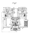
- the fluid pressure control relay valve apparatus comprises a housing having upper and lower body parts 1 and 2 sealingly clamped together by screws (not shown).
- the lower port 2 is provided with a fluid pressure delivery port 3 and a fluid pressure input port 4 separated from the delivery port by a delivery valve element 5 carried on a lower end of a valve stem 6 the upper end of which carries a larger diameter valve element 8.
- Element 5 has a seat 5a and the two mechanically linked valve elements form a double valve which is urged into the position shown by means of a light spring denoted by reference 7.
- the vent valve element 8 is engageable by a vent valve seat 8a formed integrally with a pressure responsive member in the form of a piston 9.
- the piston 9 has respective smaller and larger diameter seals slideable in respective bores 25 and 26 to define a lower pressure responsive area 10 subject to pressure at the delivery port and an upper pressure responsible area 11 connecting with a control pressure chamber 12.
- a central passage 13 of the piston 9 communicates with a vent port 14 of the device.
- the effective diameter of seat 8a is substantially the same as bore 26.
- a first normally closed electro-magnetically operable solenoid valve 15 and a second normally open electro-magnetically operable solenoid valve 16 supply of fluid pressure to input passage 17 of solenoid 15 is derived from the fluid pressure input port 4, is indicated by the dotted line connection 19.
- the valve 15 comprises a movable valve member 20 which moves away from a valve seat 20a to connect fluid pressure to the control chamber 12 when the valve is energised whereas the valve 16 comprises a valve member 22 which when energised engages seat 22a to close off a vent passage 21 from the control chamber 12.
- Fig 2 wherein the relay valve device of Fig. 1 is denoted by the block 31 with the electro-magnetic valves 15 and 16 being denoted by the same references as in Fig. 1.
- the fluid pressure input port is supplied with fluid pressure from a fluid pressure source, preferably of compressed air denoted by reference 32, delivered pressure appearing at the delivery port 3 from which a communication is made to a pressure transducer 33 for converting the pressure signal at 3 into an electrical signal which is applied to one input of a signal comparator and control unit 35 a command signal to which is supplied by a command signal generator 34.
- Appropriate combinations of electrical signals are produced by the comparator and control unit 25 for selectively energising the operable electro-magnetically operable valves 15 and 16.
- valves 15 and 16 are operated with a quick response to conditions which are opposite to those shown in Fig.1. Compressed air is thus immediately applied via the connection 19 to the control chamber 12 to urge member 19 downwards so that the seat 8a engages the valve element 8 to close off the delivery port from atmosphere.
- the force of spring 7 and the area of the inlet valve seat 5a afford some stability in that condition to which is added the effect of the area under valve element 8. There is therefore some hysteresis in the assembly. Further downward movement is communicated mechanically via stem 6 to the delivery valve element 5 whereby when the stability is overcome, fluid pressure is communicated from port 4 to the delivery port 3.
- the electro-magnetically operable valve 16 is immediately de-energised to effect partial venting of the control chamber pressure down to a value which gives rise to a reduced delivered pressure, attainment of which is sensed by the transducer 33, whereupon 35 causes re-energisation and closure of 16.
- valve apparatus Whilst in the valve apparatus described above two separate electropneumatic valves 15 and 16 are provided one of which is energised to connect a supply pressure source to a control chamber and the other of which is energised to cause venting, these modes may be varied. For example, in certain applications it may be preferred that the first such valve is normally open whilst the venting valve is still normally closed when de-energised. Again, whilst these two valves are illustrated as separate valves and thereby may offer the possibility of a 'hold' function when they are both closed, where such 'hold' function is not needed, they may if closed, for certain applications be combined with a suitable solenoid operable double valve arrangement.
- valve element 8 and its respective seat 8a being of substantially greater diameter than the respective diameters of element 5 and its seat, rapid pressure reductions can also be effected with minimal movement of the piston 9.
- This provides a particular benefit in that the volume of control chamber can be maintained very small along with the capacity of the electromagnetic valves 15 and 16.
- the relay valve device is thereby eminently suitable for controlling elemental pressure variations as required in electronic braking control systems which may also provide means for preventing wheel locking by sensing unacceptable increase of wheel deceleration.
- valves such as 15 and 16 respectively of the normally closed and normally open type leakage across the element of valve 15 may not result in slow spurious brake application, since the chamber 12 is normally continuously vented.
- optimised orifice sizes fine pressure control is readily achieved and air consumption is minimal.
Landscapes
- Engineering & Computer Science (AREA)
- Transportation (AREA)
- Mechanical Engineering (AREA)
- Physics & Mathematics (AREA)
- Electromagnetism (AREA)
- Fluid Mechanics (AREA)
- Valves And Accessory Devices For Braking Systems (AREA)
Applications Claiming Priority (2)
| Application Number | Priority Date | Filing Date | Title |
|---|---|---|---|
| GB888817796A GB8817796D0 (en) | 1988-07-26 | 1988-07-26 | Fluid pressure control relay valve device & apparatus |
| GB8817796 | 1988-07-26 |
Publications (2)
| Publication Number | Publication Date |
|---|---|
| EP0353003A2 true EP0353003A2 (fr) | 1990-01-31 |
| EP0353003A3 EP0353003A3 (en) | 1990-05-23 |
Family
ID=10641136
Family Applications (1)
| Application Number | Title | Priority Date | Filing Date |
|---|---|---|---|
| EP89307504A Withdrawn EP0353003A3 (en) | 1988-07-26 | 1989-07-24 | Fluid pressure control relay valve apparatus |
Country Status (2)
| Country | Link |
|---|---|
| EP (1) | EP0353003A3 (fr) |
| GB (1) | GB8817796D0 (fr) |
Cited By (4)
| Publication number | Priority date | Publication date | Assignee | Title |
|---|---|---|---|---|
| EP0582990A1 (fr) * | 1992-08-12 | 1994-02-16 | Grau Gmbh | Valve de commande pour remorques pour systèmes de freinage de véhicules |
| EP1028043A3 (fr) * | 1999-02-11 | 2003-04-02 | WABCO GmbH & CO. OHG | Dispositif de commande de pression hydraulique |
| WO2010094962A1 (fr) * | 2009-02-21 | 2010-08-26 | Haldex Brake Products Limited | Ensemble vanne |
| CN102917929A (zh) * | 2010-06-02 | 2013-02-06 | 霍尔德克斯制动产品有限公司 | 气门组件 |
Family Cites Families (1)
| Publication number | Priority date | Publication date | Assignee | Title |
|---|---|---|---|---|
| DE3240277A1 (de) * | 1982-10-30 | 1984-05-03 | Robert Bosch Gmbh, 7000 Stuttgart | Druckmittel-bremsanlage |
-
1988
- 1988-07-26 GB GB888817796A patent/GB8817796D0/en active Pending
-
1989
- 1989-07-24 EP EP89307504A patent/EP0353003A3/en not_active Withdrawn
Cited By (8)
| Publication number | Priority date | Publication date | Assignee | Title |
|---|---|---|---|---|
| EP0582990A1 (fr) * | 1992-08-12 | 1994-02-16 | Grau Gmbh | Valve de commande pour remorques pour systèmes de freinage de véhicules |
| EP1028043A3 (fr) * | 1999-02-11 | 2003-04-02 | WABCO GmbH & CO. OHG | Dispositif de commande de pression hydraulique |
| WO2010094962A1 (fr) * | 2009-02-21 | 2010-08-26 | Haldex Brake Products Limited | Ensemble vanne |
| CN102325677A (zh) * | 2009-02-21 | 2012-01-18 | 霍尔德克斯制动产品有限公司 | 阀门组件 |
| US8899387B2 (en) | 2009-02-21 | 2014-12-02 | Haldex Brake Products Limited | Valve assembly |
| CN102325677B (zh) * | 2009-02-21 | 2015-05-06 | 霍尔德克斯制动产品有限公司 | 阀门组件 |
| CN102917929A (zh) * | 2010-06-02 | 2013-02-06 | 霍尔德克斯制动产品有限公司 | 气门组件 |
| CN102917929B (zh) * | 2010-06-02 | 2015-10-21 | 霍尔德克斯制动产品有限公司 | 气门组件 |
Also Published As
| Publication number | Publication date |
|---|---|
| EP0353003A3 (en) | 1990-05-23 |
| GB8817796D0 (en) | 1988-09-01 |
Similar Documents
| Publication | Publication Date | Title |
|---|---|---|
| US3977734A (en) | Valve unit for braking pressure control in wheeled vehicles | |
| JPH03134385A (ja) | 電磁作動弁 | |
| US4077674A (en) | Linearly operative electric/fluid pressure valve device | |
| US4565209A (en) | Pressure regulating valve with feedback control | |
| US5039069A (en) | Electromagnetically actuated valve device | |
| US5979503A (en) | ABS modulator solenoid with a pressure balancing piston | |
| EP0498584A1 (fr) | Valve modulatrice pour fluide de pression | |
| EP0353003A2 (fr) | Soupape relais de commande de pression de fluide | |
| US3749125A (en) | Solenoid-actuated pneumatic actuator for anti-skid vehicle braking systems | |
| EP0403144A2 (fr) | Assemblages de soupape pour fluides | |
| US3536089A (en) | Electric to fluid pressure transducer | |
| US4753494A (en) | Vehicle antilock braking systems | |
| GB2069643A (en) | Deceleration sensing valves for vehicle brake proportioning valves | |
| US4068902A (en) | Adaptive braking modulator with electrically activated relay valve | |
| EP1781518A1 (fr) | Ensemble soupape | |
| US3888603A (en) | Compressor governor | |
| US4653811A (en) | Relay valve device | |
| GB2335480A (en) | Electropneumatic pressure regulator | |
| US5154203A (en) | Proportional modulator for an electropneumatic braking system | |
| US3743364A (en) | Valve | |
| US4157849A (en) | Continuous quick service apparatus for vehicle braking control | |
| JPS529275B2 (fr) | ||
| US4666217A (en) | Load controller brake force controller for pneumatic motor vehicle or motor vehicle trailer brake systems | |
| JP2710705B2 (ja) | 圧力制御弁及びその圧力制御方法 | |
| US4045093A (en) | Dynamic blending with a spring-applied fluid pressure released service brake including cojoint spring and fluid pressure emergency feature |
Legal Events
| Date | Code | Title | Description |
|---|---|---|---|
| PUAI | Public reference made under article 153(3) epc to a published international application that has entered the european phase |
Free format text: ORIGINAL CODE: 0009012 |
|
| AK | Designated contracting states |
Kind code of ref document: A2 Designated state(s): BE DE ES FR GB IT NL SE |
|
| PUAL | Search report despatched |
Free format text: ORIGINAL CODE: 0009013 |
|
| AK | Designated contracting states |
Kind code of ref document: A3 Designated state(s): BE DE ES FR GB IT NL SE |
|
| STAA | Information on the status of an ep patent application or granted ep patent |
Free format text: STATUS: THE APPLICATION IS DEEMED TO BE WITHDRAWN |
|
| 18D | Application deemed to be withdrawn |
Effective date: 19901126 |