EP0352933B1 - Verfahren und Apparat zum Formen einer doppelkonischen Schraubenfeder - Google Patents
Verfahren und Apparat zum Formen einer doppelkonischen Schraubenfeder Download PDFInfo
- Publication number
- EP0352933B1 EP0352933B1 EP89307026A EP89307026A EP0352933B1 EP 0352933 B1 EP0352933 B1 EP 0352933B1 EP 89307026 A EP89307026 A EP 89307026A EP 89307026 A EP89307026 A EP 89307026A EP 0352933 B1 EP0352933 B1 EP 0352933B1
- Authority
- EP
- European Patent Office
- Prior art keywords
- coil spring
- forming die
- coil
- head
- forming
- Prior art date
- Legal status (The legal status is an assumption and is not a legal conclusion. Google has not performed a legal analysis and makes no representation as to the accuracy of the status listed.)
- Expired - Lifetime
Links
Images


Classifications
-
- B—PERFORMING OPERATIONS; TRANSPORTING
- B21—MECHANICAL METAL-WORKING WITHOUT ESSENTIALLY REMOVING MATERIAL; PUNCHING METAL
- B21F—WORKING OR PROCESSING OF METAL WIRE
- B21F3/00—Coiling wire into particular forms
- B21F3/10—Coiling wire into particular forms to spirals other than flat, e.g. conical
Definitions
- the present invention relates to a method and an apparatus for forming a coil spring, more particularly a barrel coil spring wherein each end has consecutive coils with decreasing coil diameters.
- Such apparatus comprises a rotatable mandrel about which is wound a heated steel rod.
- Means are provided to clamp one end of the steel rod onto the mandrel and, as the mandrel is rotated, guide means serve to guide the rod as the mandrel traverses along its longitudinal axis to form the coil spring. Once formed, the mandrel may be withdrawn and the coil spring removed from the apparatus.
- Such devices have proven very efficient for the manufacture of coil springs having substantially uniform coil diameters. These devices may also be utilized to form coil springs having one barrel end wherein the consecutive coils adjacent this end have decreasing coil diameters.
- the rotating mandrel may be formed with a reduced diameter end portion so as to form the coils having decreasing diameters near the end of the coil spring.
- the length of the mandrel is greater than that of the coil spring and since the mandrel must be withdrawn longitudinally from within the coil spring after the completion of the forming process, it is not possible to form a barrel shaped coil spring, wherein both ends have coils with decreasing diameters, utilizing this apparatus.
- a shaping member or winding jig is inserted into the coil spring near the second end which is to be reshaped from that having a generally uniform coil diameter to one having consecutively decreasing diameters, and the end of the spring is attached to a rotatable head or spindle.
- the spring is clamped to the device and the rotatable head or spindle is rotated so as to form the second barrel end. Subsequently the shaping member or winding jig is withdrawn and the spring is unclamped and removed from the device.
- the apparatus involved has proven to be extremely complex resulting in relatively high manufacturing costs and inherently decreasing the reliability of the apparatus.
- the complexity of the device is increased due to the necessity of having the shaping member inserted into the coil undergo both radial and longitudinal motion to be properly positioned within the coil spring, or to provide the rotary spindle with both rotational and laterally transverse movement capabilities.
- the number of coil turns that may be reduced in diameter is somewhat limited due to the positioning of the shaping member or winding jig and also since only the roll in head or the rotary spindle can provide the requisite rotation to the end of the coil spring.
- the present invention provides a method and apparatus for forming a barrel coil spring, more particularly the formation of a second barrel end on a pre-formed spring.
- the spring may be formed having a first barrel end and a second end with generally uniform coil diameters by the standard coil spring forming mandrel apparatus.
- the apparatus according to the invention may also be utilized to form barrel ends on both ends of the coil spring.
- the invention provides a method of forming a coil spring with a reduced coil diameter end portion, wherein one end of the coil spring is attached to a first rotatable head; characterised by the further steps of:
- the invention provides apparatus for forming a coil spring with a reduced coil diameter end portion, including a rotatable head and clamping means to attach an end of the coil spring to the rotatable head; characterised by: a forming die head having at least one forming die and an associated clamp mounted thereon; feed means associated with the forming die head to feed the at least one forming die between generally uniform diameter coils near the said end of the spring such that the or each forming die bears against an inner surface of a coil to hold the coil fixed against an associated die clamp; first rotating means for rotating the rotatable head in a first direction about an axis substantially coincident with the longitudinal axis of the coil spring; and second rotating means for rotating the forming die head and its associated die clamp in a second direction, opposite to the first direction, about an axis substantially coincident with the longitudinal axis of the coil spring.
- one or more forming dies formed in halves they can be inserted into the coil spring in a direction substantially perpendicular to the axis of the coil spring without the need for any subsequent longitudinal motion. This eliminates the necessity of apparatus for providing such a complex motion to the forming die required by the prior art devices.
- the rotation of the rotatable head in one direction while rotating the forming die or dies in the opposite direction eliminates the need to provide for additional complex motion of the rotatable head required by the prior art devices.
- the present invention also eliminates the necessity of providing rotatable support rolls to locate the coil spring with respect to the rotatable head and the forming dies of the prior art devices.
- the apparatus according to the invention also enables the number of coils having reduced diameters to be varied merely by increasing or decreasing the number of forming dies.
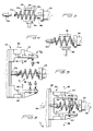
- Figure 1 shows a cross sectional view of barrel coil spring 10 wherein the diameters of the coils decrease in directions toward the spring ends.
- Such springs may be fabricated on the apparatus shown in Figure 2 which comprises machine base 12 on which are mounted carriages 14 and 16. Each of the carriages 14 and 16 is movable with respect to machine base 12 in directions indicated by arrows 18.
- Hand wheels 20 and 22 may be interconnected with the carriages 14 and 16, respectively, by known means such that their rotation will cause the carriages to move along their indicated paths.
- Rotatable head 24 is mounted on carriage 14 and may be driven by motor 26 through gears 28 and 30. Although a motor and gear drive system is shown, it is to be understood that other means may be provided to rotate rotatable head 24 about its longitudinal axis 32 without exceeding the scope of this invention.
- a forming die head, indicated generally at 34 is rotatably attached to carriage 16 such that it may rotate about axis 36 which is substantially parallel to axis 32. Again, any known means may be utilized to rotate the forming die head 34 about this axis, the precise means forming no part of the instant invention.
- Forming die head 34 comprises rotatable base member 38 with jaw members 40 and 42 slidably attached thereto. Each of the jaw members is attached to rotatable base member 38 so as to move with respect thereto in directions substantially perpendicular to rotational axis 36.
- Known feed means are provided between rotatable base 38 and the jaw members 40 and 42 so as to move them toward or away from axis 36, the precise means forming no part of the instant invention. Suffice to say that tool feed means are well known in the art and any such means may be utilized to move the jaw members 40 and 42.
- the coil spring 10 as shown in Figure 3, may be initially formed with a first end having a barrel configuration denoted by consecutive coils 10a and 10b which have decreasing diameters in a direction toward the first end of the spring. Coils 10c-10e are formed so as to have a generally uniform coil diameter.
- the spring may be formed in this configuration by known coil spring forming machines and is transferred to the apparatus shown in Figure 1 by gripping jaws 44 and 46. The transfer of the coil spring from the initial forming apparatus to the apparatus shown in Figure 2 is such that the temperature of the coil spring rod is elevated so as to permit formation of the second barrel end. Gripping jaws 44 and 46 may be manipulated manually or may form part of an automatic transfer means shown in Figures 13 and 14 which will be described in more detail hereinafter.
- Rotatable head 24 has shaping die 48 extending from one end and a clamping means associated therewith so as to clamp the second end of the spring onto the shaping die.
- the clamping means may comprise a clamping jaw 50 attached to the rotatable head 24 so as to be movable in directions indicated by arrows 52 in Figure 10.
- the second end of coil spring 10 is attached to shaping die 48 by clamping jaw 50 as illustrated in Figure 10.
- the first end of the coil spring is supported via shaft 54, associated with forming die head 34. Gripping jaws 44 and 46 are removed from the spring and withdrawn.
- Forming die head 34 is then advanced in the direction of arrow 56 from its retracted position until the position shown in Figure 5 is reached.
- Jaw members 40 and 42 each have at least one forming die 58 mounted thereon which extends toward coil spring 10.
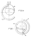
- the forming dies 58 as shown in Figures 8 and 9, comprise a generally semi-cylindrical portion 58a mounted to the jaw members via mounting rods 58b.
- the curved outer surfaces of the forming dies 58a may define a groove therein to accommodate coils of spring 10.
- Jaw members 40 and 42 are moved in the direction of arrows 60 to insert the forming dies 58 between adjacent coils until they each bear against an inner surface of the coil spring 10 and clamp the coil spring to one jaw 42 by co-operating with an associated die clamp 66.
- rotatable head 24 is rotated in a first direction, indicated by arrow 62 in Figures 6 and 9.
- forming die head 34 is rotated in the opposite direction indicated by arrow 64 in figures 6 and 9.
- Rotation of forming die head 34 causes forming dies 58 as well as die clamp 66, attached to jaw member 42 and bearing against an outer surface of the coil spring, to rotate therewith a predetermined amount, usually not exceeding 360°.
- forming die 58 is shown attached to each of the jaw members 40 and 42 in Figures 5, 6 and 8, it is to be understood that more than one such forming die can be associated with the jaw members as illustrated in Figure 2.
- gripping jaws 72 and 74 grip coil spring 10, and rotatable head 24 and shaft 54 are withdrawn in the direction of arrows 76 and 78, respectively.
- the gripping jaws then transfer the completely formed coil spring 10 to a heat treating or cooling operation.
- the apparatus may be slightly modified, as shown in Figure 12 to incorporate an automatic feed system for carriage 16.
- the rotatable head 24, the rotatable base member 38, the jaw members 40 and 42, as well as the forming dies 58 function exactly the same as in the previously described embodiment and have been indicated by the same numbers in Figure 12.
- the traversing of carriage 16 in the direction of arrows 18 is accomplished by cylinder 80 mounted on machine base 12 and having an extendable and retractable piston rod 82 attached to carriage 16.
- Cylinder 80 may be actuated by hydraulic or pneumatic fluid and may form part of an automatic control system which automatically positions carriage 16 and actuates the motions of jaw members 40 and 42.
- Such a system may also encompass the clamping and unclamping of clamp 50 so as to clamp or release the end of spring 10 as well as the rotation and longitudinal positioning of rotatable head 24.
- the fully automated apparatus shown in Figure 12 may be part of the automated assembly line shown in Figures 13 and 14. It is envisioned that such an automated assembly line would comprise a known coil spring mandrel apparatus 84 which would produce the coil spring having one barrel end while the other end has generally uniform coil diameters as indicated in Figure 3. The structural details and the operation of such machines are well known in the art and no further description is believed to be necessary.
- Transfer means 88 may comprise a base portion 90 having a transfer arm 92 rotatably attached thereto so as to rotate about an axis substantially parallel to that of the coil spring 10. Arm 92 has gripping jaws 94 attached thereto such that spring 10 may be gripped between them. Gripping jaws 94 may be actuated by known means so as to selectively grip and release coil spring 10. First transfer means 88 also has means thereon to rotate arm 92 about its axis in the direction of arrow 96 so as to transfer the coil spring 10 from the winding apparatus 84 to the barrel forming apparatus 86. Arm 94 may be extended or retracted via cylinder 98 so as to properly locate the coil spring 10 in the respective apparatus.
- Apparatus 86 carries out the previously described functions of forming the barrel shape on the second end of the coil spring as illustrated in Figs. 5-7.
- second transfer means 100 tranfers the formed coil spring from apparatus 86 to a quench dunk tank illustrated at 102.
- Second transfer device 100 may also comprise a base 104 having an arm 106 rotatably attached thereto so as to rotate about an axis substantially parallel to the rotational axis of arm 92.
- Rotatable arm 106 has gripping jaws 108 attached thereto and means thereon to selectively grip and release the coil spring 10.
- rotatable head 24 and the shaft 54 are retracted (see Fig. 7) and arm 106 is rotated in the direction of arrow 110 to transfer the coil spring to the quench dunk tank 102.
- arm 106 may be extended and retracted by way of cylinder 112 associated therewith.
Claims (10)
- Verfahren zum Formen einer Schraubenfeder (10) mit einem einen verringerten Schraubendurchmesser aufweisenden Endabschnitt, wobei das eine Ende der Schraubenfeder mit einem ersten rotierbaren Kopf (24) verbunden wird; gekennzeichnet durch die weiteren Schritte:a) Einsetzen wenigstens eines Umform- oder Biegegesenkes (58, 58a) in einer im wesentlichen senkrecht zu der Längsachse der Schraubenfeder verlaufenden Richtung zwischen einander benachbarten Windungen der Feder, um gegen eine innere Oberfläche einer Windung zu drücken und um die Schraube oder Windung im Zusammenwirken mit einer Form-Klemm- oder Spannbacke (66) festzuklemmen oder festzuspannen;b) Drehen des ersten rotierbaren Kopfes in einer ersten Richtung um eine Achse, welche im wesentlichen mit der Längsachse der Schraubenfeder koinzidiert; undc) Drehen des mindestens einen Umform- oder Biegegesenkes und seiner zugeordneten Klemm- oder Spannbacke in einer zweiten, zu der ersten Richtung entgegengesetzten Richtung um eine Achse, welche im wesentlichen mit der Längsachse der Schraubenfeder zusammenfällt.
- Verfahren nach Anspruch 1, gekennzeichnet durch den zusätzlichen Schritt des Einsetzens eines zweiten Umform- oder Biegegesenkes (58, 58b) zwischen einander benachbarten Windungen der Schraubenfeder in einer Richtung, die im wesentlichen entgegengesetzt zu derjenigen des genannten einen Umform- oder Biegegesenkes ist, bevor der rotierbare Kopf in Rotation versetzt wird, derart, daß das zweite Umform- oder Biegegesenk gegen eine innere Oberfläche einer Windung drückt.
- Verfahren nach Anspruch 1 oder 2, gekennzeichnet durch den zusätzlichen Schritt des Zuführens des oder eines jeden der genannten Gesenke in einer Richtung, die im wesentlichen parallel zu der Längsachse der Schraubenfeder verläuft, und zwar von einer zurückgezogenen Stellung aus, in welcher es von der Schraubenfeder bis zu einer Bearbeitungsposition zurückgezogen ist, welche der Schraubenfeder benachbart liegt, bevor das oder die Umform- oder Biege-Gesenke zwischen einander benachbarten Windungen der Feder eingesetzt wird oder werden.
- Verfahren nach einem der vorhergehenden Ansprüche, dadurch gekennzeichnet, daß das oder ein jedes der genannten Umform- oder Biegegesenke in der ersten Richtung um einen Betrag gedreht wird, der nicht größer als 180° ist.
- Verfahren nach einem der vorhergehenden Ansprüche, dadurch gekennzeichnet, daß das oder ein jedes der genannten Umform- oder Biegegesenke in der zweiten Richtung um einen Betrag gedreht wird, der nicht größer als 360° ist.
- Vorrichtung zum Formen einer Schraubenfeder (10) mit einem einen verringerten Schraubendurchmesser aufweisenden Endabschnitt, mit einem rotierbaren Kopf (24) und Spannmitteln (50), um ein Ende der Schraubenfeder an dem rotierbaren Kopf anzubringen; gekennzeichnet durch: einen Umform- oder Biegegesenkkopf (34) mit wenigstens einem daran befestigten Umform- oder Biegegesenk (58) und einer zugeordneten Klemm- oder Spannbacke (66); Zuführmittel, welche dem Umform- oder Biegegesenk-Kopf zugeordnet sind, um wenigstens ein Umform- oder Biegegesenk zwischen Windungen von einem im wesentlichen gleichförmigen Durchmesser nahe dem genannten Ende der Feder zuzuführen, derart, daß das oder jedes Umform- oder Biegegesenk gegen eine innere Oberfläche einer Windung drückt, um die Windung fest gegen eine zugeordnete Klemm- oder Spannbacke zu halten; erste Drehmittel (26, 28, 30) zum Drehen des rotierbaren Kopfes in einer ersten Richtung um eine Achse, welche im wesentlichen mit der Längsachse der Schraubenfeder zusammenfällt; und zweite Drehmittel zum Drehen des Umform- oder Biegegesenk-Kopfes und seiner zugeordneten Klemm- oder Spannbacke in einer zweiten Richtung, welche zu der ersten Richtung entgegengesetzt ist, und zwar um eine im wesentlichen mit der Längsachse der Schraubenfeder zusammenfallenden Achse.
- Vorrichtung nach Anspruch 6, ferner gekennzeichnet durch Mittel (80, 82) zum Vorwärtsbewegen des Form- oder Biegegesenk-Kopfes in einer im wesentlichen parallel zu der Längsachse der Schraubenfeder verlaufenden Richtung zwischen einer Bearbeitungsposition, in welcher das wenigstens eine Umform- oder Biegegesenk der Schraubenfeder benachbart ist, und einer zurückgezogenen Position, in welcher es von dieser zurückgezogen ist.
- Vorrichtung nach Anspruch 6 und 7, dadurch gekennzeichnet, daß die ersten Drehmittel so angeordnet sind, daß sie den rotierbaren Kopf in einer ersten Richtung um nicht mehr als 180° drehen.
- Vorrichtung nach einem der Ansprüche 6 bis 8, dadurch gekennzeichnet, daß die zweiten Drehmittel so angeordnet sind, daß sie den Umform- oder Biegegesenk-Kopf in der zweiten Richtung um nicht mehr als 360° drehen.
- Vorrichtung nach einem der Ansprüche 6 bis 9, dadurch gekennzeichnet, daß der Umform- oder Biegegesenk-Kopf aufweist:a) ein rotierbares Basis-Element (38);b) erste und zweite Klemmbacken-Elemente (40, 42), welche in gleitbarer oder verschiebbarer Weise an dem rotierenden Basis-Element angebracht sind;c) wenigstens ein erstes Umform- oder Biegegesenk (58), welches an dem ersten Klemmbacken-Element (40) befestigt ist;d) wenigstens ein zweites Umform- oder Biegegesenk (58), welches an dem zweiten Klemmbacken-Element (42) befestigt ist; unde) Mittel (30) zum Verbinden der ersten und zweiten Klemmbacken-Elemente mit den Zuführmitteln, derart, daß die Zuführmittel die Klemmbacken-Elemente aufeinanderzu oder voneinanderweg bewegen, und zwar in einer Richtung, die im wesentlichen senkrecht zu der Längsachse der Schraubenfeder verläuft.
Applications Claiming Priority (2)
| Application Number | Priority Date | Filing Date | Title |
|---|---|---|---|
| US07/224,143 US4945744A (en) | 1988-07-26 | 1988-07-26 | Method and apparatus for forming a barrel coil spring |
| US224143 | 1988-07-26 |
Publications (3)
| Publication Number | Publication Date |
|---|---|
| EP0352933A2 EP0352933A2 (de) | 1990-01-31 |
| EP0352933A3 EP0352933A3 (en) | 1990-10-24 |
| EP0352933B1 true EP0352933B1 (de) | 1994-02-02 |
Family
ID=22839433
Family Applications (1)
| Application Number | Title | Priority Date | Filing Date |
|---|---|---|---|
| EP89307026A Expired - Lifetime EP0352933B1 (de) | 1988-07-26 | 1989-07-11 | Verfahren und Apparat zum Formen einer doppelkonischen Schraubenfeder |
Country Status (6)
| Country | Link |
|---|---|
| US (1) | US4945744A (de) |
| EP (1) | EP0352933B1 (de) |
| JP (1) | JP2648369B2 (de) |
| CA (1) | CA1333355C (de) |
| DE (1) | DE68912840T2 (de) |
| ES (1) | ES2048842T3 (de) |
Families Citing this family (9)
| Publication number | Priority date | Publication date | Assignee | Title |
|---|---|---|---|---|
| US7198068B2 (en) * | 2003-08-28 | 2007-04-03 | Meritor Suspension Systems Co. | Cassette pigtailing machine for a coil spring |
| JP4011603B1 (ja) * | 2006-05-30 | 2007-11-21 | 三菱製鋼株式会社 | コイルバネ端部成形装置およびコイルバネ端部成形方法 |
| ES2292354B1 (es) * | 2006-07-28 | 2009-02-16 | C.A.V. Ventacan, S.L. | Dispositivo de union para estructuras a base de perfiles de aluminio. |
| JP4536701B2 (ja) * | 2006-11-06 | 2010-09-01 | 三菱製鋼株式会社 | コイルバネ形成装置 |
| KR100952844B1 (ko) * | 2007-12-20 | 2010-04-15 | 대원강업주식회사 | 배럴형 코일 스프링의 제작 장치 및 방법 |
| US8651510B2 (en) * | 2008-01-04 | 2014-02-18 | Innovare Motion Pty Ltd. | Trailer with lowerable and raisable trailer bed |
| KR101134708B1 (ko) * | 2009-11-30 | 2012-04-16 | 대원강업주식회사 | 코일 스프링용 피그 테일 가공장치 |
| US8912472B1 (en) * | 2010-07-19 | 2014-12-16 | Barnes Group Inc. | Induction heating of springs |
| JP6199139B2 (ja) | 2013-09-26 | 2017-09-20 | 中央発條株式会社 | コイルばねの成形方法及び成形装置 |
Family Cites Families (9)
| Publication number | Priority date | Publication date | Assignee | Title |
|---|---|---|---|---|
| US1676598A (en) * | 1928-07-10 | Spring-forming machine | ||
| US2335423A (en) * | 1939-12-15 | 1943-11-30 | Knoop Hendrikus | Machine for making helically wound barrel-shaped springs |
| DE2330208A1 (de) * | 1973-06-14 | 1975-01-02 | Roechling Burbach Gmbh Stahl | Verfahren und vorrichtung zum herstellen von beidseitig kegelstumpf-, tonnen- oder kugelfoermigen schraubenfedern |
| FR2477045A1 (fr) * | 1980-03-03 | 1981-09-04 | Ressorts Ind | Procede et appareillage pour la fabrication de ressorts miniblocs |
| DE3020958C2 (de) * | 1980-06-03 | 1985-09-26 | Hoesch Ag, 4600 Dortmund | Verfahren und Vorrichtung zur Herstellung von Doppelkegelfedern oder dergleichen |
| JPS5725233A (en) * | 1980-07-18 | 1982-02-10 | Nhk Spring Co Ltd | Formation of coil spring |
| JPS59199135A (ja) * | 1983-04-26 | 1984-11-12 | Morita Tekkosho:Kk | コイルばねのピツグテイル成形方法およびこれを実施するための装置 |
| US4682394A (en) * | 1985-08-27 | 1987-07-28 | Leggett & Platt, Incorporated | Bedding and seating product having double twist coil spring and method and apparatus for manufacturing the same |
| US4719683A (en) * | 1985-12-30 | 1988-01-19 | Windwinder Corporation | Preloaded spring, method and apparatus for forming same |
-
1988
- 1988-07-26 US US07/224,143 patent/US4945744A/en not_active Expired - Lifetime
-
1989
- 1989-07-11 ES ES89307026T patent/ES2048842T3/es not_active Expired - Lifetime
- 1989-07-11 DE DE68912840T patent/DE68912840T2/de not_active Expired - Fee Related
- 1989-07-11 EP EP89307026A patent/EP0352933B1/de not_active Expired - Lifetime
- 1989-07-25 JP JP1190707A patent/JP2648369B2/ja not_active Expired - Fee Related
- 1989-07-26 CA CA000606759A patent/CA1333355C/en not_active Expired - Fee Related
Also Published As
| Publication number | Publication date |
|---|---|
| JP2648369B2 (ja) | 1997-08-27 |
| EP0352933A3 (en) | 1990-10-24 |
| CA1333355C (en) | 1994-12-06 |
| DE68912840T2 (de) | 1994-08-18 |
| EP0352933A2 (de) | 1990-01-31 |
| JPH0270342A (ja) | 1990-03-09 |
| US4945744A (en) | 1990-08-07 |
| DE68912840D1 (de) | 1994-03-17 |
| ES2048842T3 (es) | 1994-04-01 |
Similar Documents
| Publication | Publication Date | Title |
|---|---|---|
| US5499522A (en) | Double-head pipe bending machine | |
| JP3685526B2 (ja) | パイプの曲げ加工装置 | |
| EP0352933B1 (de) | Verfahren und Apparat zum Formen einer doppelkonischen Schraubenfeder | |
| GB2076714A (en) | Method and apparatus for manufacturing double conical springs and the like | |
| JPS5836577B2 (ja) | 電気的な機械のステ−タのコイルを巻線する装置 | |
| US4061009A (en) | Machine for spinning tubular workpieces | |
| US3563119A (en) | Method for cutting tube members and finishing selected of the cut tube edges at a single station | |
| US4625531A (en) | Bending machine | |
| US4479373A (en) | Tube bending assembly, particularly for thin wall and small and medium diameter metal tubes | |
| US20030213278A1 (en) | Bending machine for tubing, bar and the like | |
| EP0323534B1 (de) | Formvorrichtung für eine Federwickelmaschine und Verfahren zum Auswechseln dieser Formvorrichtung | |
| JPS59132756A (ja) | コイル巻成法とコイルワインダ | |
| CA1041747A (en) | Method and device for the cold working of heat exchanger tubes for the attachment of spiral fins | |
| US3718797A (en) | Lapping machine for the production of reinforcement baskets with bell sleeve | |
| EP1468756B1 (de) | Verfahren und Vorrichtung zum Biegen von rohrförmigen Werkstücken mit veränderlichem Biegeradius | |
| US3662940A (en) | Method and apparatus for forming cylinders from strip material | |
| US5217562A (en) | Machine for coiling and winding tubular sleeves of elastomeric material incorporating reinforcing fibers | |
| JP3858182B2 (ja) | コイルばねの製造方法およびその装置 | |
| US3823883A (en) | Apparatus for wrapping pipe with multiple strips | |
| GB2035170A (en) | Manufacture of seamless ball housings | |
| US4112727A (en) | Method and apparatus for making pipe flanges | |
| CN107639421B (zh) | 一种集气管加工设备及其加工工艺 | |
| US3225579A (en) | Squaring spring flat for coiling machine | |
| US3453854A (en) | Method of making tubes | |
| JP2778802B2 (ja) | 連続熱間鍛造方法及び装置 |
Legal Events
| Date | Code | Title | Description |
|---|---|---|---|
| PUAI | Public reference made under article 153(3) epc to a published international application that has entered the european phase |
Free format text: ORIGINAL CODE: 0009012 |
|
| AK | Designated contracting states |
Kind code of ref document: A2 Designated state(s): DE ES FR GB IT |
|
| PUAL | Search report despatched |
Free format text: ORIGINAL CODE: 0009013 |
|
| AK | Designated contracting states |
Kind code of ref document: A3 Designated state(s): DE ES FR GB IT |
|
| 17P | Request for examination filed |
Effective date: 19901210 |
|
| 17Q | First examination report despatched |
Effective date: 19920811 |
|
| GRAA | (expected) grant |
Free format text: ORIGINAL CODE: 0009210 |
|
| AK | Designated contracting states |
Kind code of ref document: B1 Designated state(s): DE ES FR GB IT |
|
| ITF | It: translation for a ep patent filed |
Owner name: INTERPATENT ST.TECN. BREV. |
|
| REF | Corresponds to: |
Ref document number: 68912840 Country of ref document: DE Date of ref document: 19940317 |
|
| REG | Reference to a national code |
Ref country code: ES Ref legal event code: FG2A Ref document number: 2048842 Country of ref document: ES Kind code of ref document: T3 |
|
| ET | Fr: translation filed | ||
| PLBE | No opposition filed within time limit |
Free format text: ORIGINAL CODE: 0009261 |
|
| STAA | Information on the status of an ep patent application or granted ep patent |
Free format text: STATUS: NO OPPOSITION FILED WITHIN TIME LIMIT |
|
| 26N | No opposition filed | ||
| REG | Reference to a national code |
Ref country code: GB Ref legal event code: IF02 |
|
| PGFP | Annual fee paid to national office [announced via postgrant information from national office to epo] |
Ref country code: GB Payment date: 20050614 Year of fee payment: 17 |
|
| PG25 | Lapsed in a contracting state [announced via postgrant information from national office to epo] |
Ref country code: GB Free format text: LAPSE BECAUSE OF NON-PAYMENT OF DUE FEES Effective date: 20060711 |
|
| GBPC | Gb: european patent ceased through non-payment of renewal fee |
Effective date: 20060711 |
|
| PGFP | Annual fee paid to national office [announced via postgrant information from national office to epo] |
Ref country code: ES Payment date: 20070723 Year of fee payment: 19 |
|
| PGFP | Annual fee paid to national office [announced via postgrant information from national office to epo] |
Ref country code: DE Payment date: 20070731 Year of fee payment: 19 |
|
| PGFP | Annual fee paid to national office [announced via postgrant information from national office to epo] |
Ref country code: IT Payment date: 20070814 Year of fee payment: 19 |
|
| PGFP | Annual fee paid to national office [announced via postgrant information from national office to epo] |
Ref country code: FR Payment date: 20070706 Year of fee payment: 19 |
|
| PG25 | Lapsed in a contracting state [announced via postgrant information from national office to epo] |
Ref country code: DE Free format text: LAPSE BECAUSE OF NON-PAYMENT OF DUE FEES Effective date: 20090203 |
|
| REG | Reference to a national code |
Ref country code: FR Ref legal event code: ST Effective date: 20090331 |
|
| PG25 | Lapsed in a contracting state [announced via postgrant information from national office to epo] |
Ref country code: IT Free format text: LAPSE BECAUSE OF NON-PAYMENT OF DUE FEES Effective date: 20080711 Ref country code: FR Free format text: LAPSE BECAUSE OF NON-PAYMENT OF DUE FEES Effective date: 20080731 |
|
| REG | Reference to a national code |
Ref country code: ES Ref legal event code: FD2A Effective date: 20080712 |
|
| PG25 | Lapsed in a contracting state [announced via postgrant information from national office to epo] |
Ref country code: ES Free format text: LAPSE BECAUSE OF NON-PAYMENT OF DUE FEES Effective date: 20080712 |