EP0352263B1 - Servosoupape a securite integree et a regulation de fuite en position extreme - Google Patents
Servosoupape a securite integree et a regulation de fuite en position extreme Download PDFInfo
- Publication number
- EP0352263B1 EP0352263B1 EP88901385A EP88901385A EP0352263B1 EP 0352263 B1 EP0352263 B1 EP 0352263B1 EP 88901385 A EP88901385 A EP 88901385A EP 88901385 A EP88901385 A EP 88901385A EP 0352263 B1 EP0352263 B1 EP 0352263B1
- Authority
- EP
- European Patent Office
- Prior art keywords
- control
- spool
- valve
- slot
- lobe
- Prior art date
- Legal status (The legal status is an assumption and is not a legal conclusion. Google has not performed a legal analysis and makes no representation as to the accuracy of the status listed.)
- Expired - Lifetime
Links
Images


Classifications
-
- F—MECHANICAL ENGINEERING; LIGHTING; HEATING; WEAPONS; BLASTING
- F15—FLUID-PRESSURE ACTUATORS; HYDRAULICS OR PNEUMATICS IN GENERAL
- F15B—SYSTEMS ACTING BY MEANS OF FLUIDS IN GENERAL; FLUID-PRESSURE ACTUATORS, e.g. SERVOMOTORS; DETAILS OF FLUID-PRESSURE SYSTEMS, NOT OTHERWISE PROVIDED FOR
- F15B20/00—Safety arrangements for fluid actuator systems; Applications of safety devices in fluid actuator systems; Emergency measures for fluid actuator systems
- F15B20/002—Electrical failure
-
- F—MECHANICAL ENGINEERING; LIGHTING; HEATING; WEAPONS; BLASTING
- F15—FLUID-PRESSURE ACTUATORS; HYDRAULICS OR PNEUMATICS IN GENERAL
- F15B—SYSTEMS ACTING BY MEANS OF FLUIDS IN GENERAL; FLUID-PRESSURE ACTUATORS, e.g. SERVOMOTORS; DETAILS OF FLUID-PRESSURE SYSTEMS, NOT OTHERWISE PROVIDED FOR
- F15B13/00—Details of servomotor systems ; Valves for servomotor systems
- F15B13/02—Fluid distribution or supply devices characterised by their adaptation to the control of servomotors
- F15B13/04—Fluid distribution or supply devices characterised by their adaptation to the control of servomotors for use with a single servomotor
- F15B13/0401—Valve members; Fluid interconnections therefor
- F15B13/0402—Valve members; Fluid interconnections therefor for linearly sliding valves, e.g. spool valves
-
- Y—GENERAL TAGGING OF NEW TECHNOLOGICAL DEVELOPMENTS; GENERAL TAGGING OF CROSS-SECTIONAL TECHNOLOGIES SPANNING OVER SEVERAL SECTIONS OF THE IPC; TECHNICAL SUBJECTS COVERED BY FORMER USPC CROSS-REFERENCE ART COLLECTIONS [XRACs] AND DIGESTS
- Y10—TECHNICAL SUBJECTS COVERED BY FORMER USPC
- Y10T—TECHNICAL SUBJECTS COVERED BY FORMER US CLASSIFICATION
- Y10T137/00—Fluid handling
- Y10T137/8593—Systems
- Y10T137/86493—Multi-way valve unit
- Y10T137/86574—Supply and exhaust
- Y10T137/86582—Pilot-actuated
- Y10T137/86614—Electric
-
- Y—GENERAL TAGGING OF NEW TECHNOLOGICAL DEVELOPMENTS; GENERAL TAGGING OF CROSS-SECTIONAL TECHNOLOGIES SPANNING OVER SEVERAL SECTIONS OF THE IPC; TECHNICAL SUBJECTS COVERED BY FORMER USPC CROSS-REFERENCE ART COLLECTIONS [XRACs] AND DIGESTS
- Y10—TECHNICAL SUBJECTS COVERED BY FORMER USPC
- Y10T—TECHNICAL SUBJECTS COVERED BY FORMER US CLASSIFICATION
- Y10T137/00—Fluid handling
- Y10T137/8593—Systems
- Y10T137/86493—Multi-way valve unit
- Y10T137/86574—Supply and exhaust
- Y10T137/8667—Reciprocating valve
- Y10T137/86694—Piston valve
- Y10T137/8671—With annular passage [e.g., spool]
Definitions
- the present invention relates generally to the field of two-stage electrohydraulic servovalves, and, more particularly, to a fail-fixed servovalve having an improved second-stage spool valve which, when in a hard-over position, deliberately controls the leakage flows to and from a control slot communicating with a load.
- a two-stage electrohydraulic servovalve is a device for converting an electrical input into a substantially-proportional hydraulic output.
- Such servovalves typically have a first-stage hydraulic amplifier, and second-stage valve spool.
- the first-stage commonly has a torque motor arranged to produce pivotal movement of a member in response to a supplied electrical current.
- the hydraulic amplifier may be of the "nozzle-flapper” type (see, e.g., U.S. Patent No. 3,023,782), the "jet pipe” type (see, e.g., U.S. Patent No. 3,922, 955), or the "deflectable jet stream” type (see, e.g., U.S. Patents No. 3,542,051 and 3,612,103).
- the hydraulic amplifier is used to produce a differential pressure, which is then used to selectively shift the second-stage valve spool in the appropriate direction relative to the body. It is also known to provide a mechanical feedback spring wire between the second-stage spool and the torque motor pivotal member such that spool displacement off null will be substantially proportional to the polarity and magnitude of the supplied current.
- Such servovalves may be further classified by the nature of the output. For example, in a “flow control” servovalve, output flow is substantially proportional to supplied current, at constant load. In a “pressure control” servovalve, the hydraulic output is a differential pressure. Other types include “pressure-flow” (PQ) servovalves, “dynamic pressure feedback” (DPF) servovalves, static load error washout” (SLEW) servovalves, and “acceleration switching” (AS) servovalves. These various types and configurations are comparatively illustrated in Technical Bulletin 103, "Transfer Functions for Moog Servovalves". Moog mc. (1965).
- a valve having a body provided with a bore; having supply, control and return slots extending into said body from said bore, said supply slot communicating with a source of pressurized fluid, said return slot communicating with a fluid return; having a valve spool operatively arranged in said bore for sliding movement between a null position and an alternative position, said spool having supply, control, and return lobes adapted to cooperate with said supply, control and return slots, respectively; each lobe being so configured and arranged with respect to its associated slot that when said spool is moved from said null position toward said alternative position, fluid is constrained to flow between said control slot and one of said supply and return slots by passing sequentially through two variable orifices, characterised in that
- control lobe and at least one of said supply and return lobes are so dimensioned and proportioned with respect to their associated slots that when said spool is in said alternative position, one of said supply and return slots is opened, the other of said supply and return slots is closed, and said control lobe blocks intended fluid flow between said control slot and such opened slot, and the ratio of impedance to leakage flows to and from said control slot is substantially equal to a predetermined value.
- the valve is thus provided with controlled leakage flows, or impedance to such leakage flows, in a hard-over condition.
- Fig. 1 is a fragmentary schematic longitudinal vertical sectional view of an improved second-stage spool valve of a two-stage electrohydraulic servovalve, this view showing the spool as being in a centered or null position relative to the body.
- Fig. 1A is an enlarged detail view of the spool left supply lobe and slot shown in Fig. 1.
- Fig. 1B is an enlarged detail view of the spool middle lobe and left return slot shown in Fig. 1.
- Fig. 1C is an enlarged detail view of the spool middle lobe and right return slot, shown in Fig. 1.
- Fig. 1D is an enlarged detail view of the spool right supply lobe and slot shown in Fig. 1.
- Fig. 1E is an enlarged detail view of the left control lobe and slot shown in Fig. 1.
- Fig. 1F is an enlarged detail view of the right control lobe and slot shown in Fig. 1.
- Fig. 2 is a view similar to Fig. 1, but shows the spool as having been shifted leftwardly to a hard-over position relative to the body.
- Fig. 2A is an enlarged detail view of the spool middle lobe and left return slot as shown in Fig. 2.
- Fig. 2B is an enlarged detail view of the spool right supply lobe and slot shown in Fig. 2.
- Fig. 2C is an enlarged detail view of the left control lobe and slot shown in Fig. 2.
- Fig. 2D is an enlarged detail view of the right control lobe and slot shown in Fig. 2.
- Fig. 3 is a view similar to Fig. 1, but shows the spool as having been shifted rightwardly relative to the body to a hard-over position.
- Fig. 3A is an enlarged detail view of the left supply lobe and slot shown in Fig. 3.
- Fig. 3B is an enlarged detail view of the spool middle lobe and right return slot shown in Fig. 3.
- Fig. 3C is an enlarged detail view of the left control lobe and slot shown in Fig. 3.
- Fig. 3D is an enlarged detail view of the right control lobe and slot shown in Fig. 3.
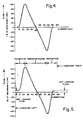
- Fig. 4 is a graph showing flow (ordinate) verses supplied current (abscissa) for a fail-fixed servovalve with balanced leakage flows.
- Fig. 5 is a graph showing flow (ordinate) verses supplied current (abscissa) for a fail-safe servovalve having deliberately mismatched leakage flows in both hard-over positions.
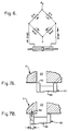
- Fig. 6 is a schematic of a hydraulic bridge circuit in which the hard-over leakage flows are arranged to slew an actuator to the right.
- Fig. 7A is a fragmentary detail view showing a modified spool at null with respect to a return slot.
- Fig. 7B is a fragmentary detail view of the structure shown in Fig. 7A, but depicts the spool as having been shifted leftwardly to a hard-over position.
- an improved second-stage spool valve generally indicated at 10, of a two-stage flow-control electrohydraulic servovalve (not fully shown), of the type depicted in U.S. Patent No. 3,023,782, is depicted as broadly including a body 11 provided with a horizontally-elongated bore, and a five-lobed valve spool 12 mounted for sealed sliding movement along the bore.
- the body is shown as having planar vertical left and right end faces 13,14, respectively, and a planar horizontal lower surface 15.
- the bore is bounded by annular vertical left and right end walls 16,18, respectively, and by an elongated inwardly-facing horizontal cylindrical surface 19 extending therebetween.
- a number of axially-spaced slot-like passageways extend into the body from bore wall 19. These various passageways may open onto the bore in the form of one or more discrete, angularly-segmented substantially-rectangular slots, or may be in the form of annular grooves, or may have some other shape, as desired.
- These various passageways may open onto the bore in the form of one or more discrete, angularly-segmented substantially-rectangular slots, or may be in the form of annular grooves, or may have some other shape, as desired.
- a first slot-and-passageway 20 communicates spool left end chamber 21 with a source (not shown) of fluid at pressure P L ;
- a second slot-and-passageway 22 communicates the bore with a source (not shown) pressurized fluid at supply pressure P s ;
- a third slot-and-passageway 23 communicates the bore with a fluid return or sump (not shown) at a return pressure R;
- a fourth slot-and-passageway 24 communicates the bore with the fluid return;
- a fifth slot-and-passageway 25 communicates the bore with the source (not shown) of fluid at supply pressure P s ; and the rightwardmost sixth slot-and-passageway 26 communicates the spool right end chamber 28 with another source of fluid at pressure P R .
- Pressures P L and P R may be provided by the servovalve amplifier section (not shown), and are selectively variable to create a pressure differential adequate to shift the spool either leftwardly or rightwardly, as desired, relative to the body. Additional details as to the structure and basic operation of such a "flow control" servo-valve may be found in U.S. Patent No. 3,023,782, the aggregate disclosure of which is hereby incorporated by reference.
- Passageways 22,25 may communicate with the same fluid source, or with different fluid sources, as desired.
- return passageways 23,24 may communicate with a common return, or with different returns or sumps, as desired.
- passageways 22,25 are both provided with the same supply pressure P s
- return passageways 23,24 both communicate with a common return.
- the respective pressures in passageways 22,23,24,25 could be different from those specifically shown.
- six passageways extend into the body from a like number of axially-spaced radial slots, which open onto bore surface 19.
- the body is further provided with left and right control slots or grooves 29,30, which extend radially into the body from bore surface 19 between slots 22,23 and 24,25, respectively.
- tapped horizontal axial holes 32,33 communicate body surfaces 13,16 and 18,14, respectively. These holes matingly receive the threaded shank portions of left and right abutment stops 34,35, respectively.
- the abutment stops are adjustably mounted on the body.
- the structure of these abutment stops has been deliberately simplified in the interest of clarity, and collateral structure (e.g., lock nuts, seals, etc.) has been omitted.
- collateral structure e.g., lock nuts, seals, etc.
- Spool 12 is mounted within the bore for sealed sliding movement therealong, and has circular vertical left and right end faces 38,39 arranged to face abutment stop surfaces 36,37, respectively.
- the spool has five axially-spaced lobes mounted on a common stem 40. Thus, proceeding from left-to-right in Fig. 1, these individual lobes are indicated at 41,42,43,44,45, respectively.
- the spool is so dimensioned and configured with respect to the bore and the various slots-and-passageways, that, when the spool is in a centered or null position relative to the body, as shown in Fig.
- the right metering edge of left spool 41 is substantially zero-lapped with respect to the left supply slot 22; the left and right metering edges of middle lobe 43 are substantially zero-lapped with respect to return slots 23,24, respectively; and the left metering edge of right lobe 45 is substantially zero-lapped with respect to right supply slot 25.
- the left and right metering edges of intermediate control lobes 42,44 are shown as being symmetrically underlapped with respect to control slots 29,30, respectively.
- Lobes 41,43 and 45 are shown as being further provided with an alternating series of lands and grooves, the grooves being severally indicated at 46 in Figs. 1A - 1F, to provide a laminar sliding seal with the bore.
- the right metering edge of left lobe 41 is defined by the intersection of a rightwardly-facing annular vertical surface 48, and the outwardly-facing horizontal cylindrical surface 49 of the right-wardmost land 50.
- land 50 is shown as having a radially clearance c1 with respect to bore surface 19, whereas each of the other lands on the lobe has a smaller radial clearance c2.
- the left edge of land 50 is coincidentally shown as being substantially zero-lapped with respect to slot 22, but this may readily be changed.
- the left metering edge of middle lobe 43 is defined by the intersection of a leftwardly-facing annular vertical surface 51, and the outwardly-facing horizontal cylindrical surface 52 of left land 53.
- Land surface 52 is shown as having a radial clearance of c1, whereas, except as described herein, the other lands of middle lobe 43 all have a smaller radial clearance of c2.
- the right edge of land 53 is overlapped with respect to slot 23.
- the right metering edge of middle lobe 43 is defined by the intersection of rightwardly-facing annular vertical surface 54, and the outwardly-facing horizontal cylindrical surface 55 of right land 56.
- Land surface 55 is spaced from bore wall 19 by a radial clearance of c1, whereas all the other lands on the middle lobe (except for left land 53) have a radial clearance of c2.
- the left metering edge of right lobe 45 is shown as being defined by the intersection of a leftwardly-facing annular vertical surface 58, and the outwardly-facing horizontal cylindrical surface 59 of left land 60.
- Land surface 59 is shown as having a radial clearance of c1 with respect to the bore, whereas the other lands on this right lobe have a radial clearance of c2.
- left and right metering edges of left control lobe 42 are defined by the intersection of outwardly-facing horizontal cylindrical surface 61 with leftwardly- and rightwardly-facing annular vertical surfaces 62,63, respectively. As previously noted, both metering edges of this lobe are underlapped by a like distance, at null, with respect to control slot 29.
- Lobe surface 61 is spaced from bore wall 19 by a radial clearance c2.
- right control lobe 44 is shown as having its left and right metering edges defined by the intersection of outwardly-facing horizontal cylindrical surface 64 with leftwardly- and rightwardly-facing annular vertical surfaces 65,66, respectively.
- Lobe surface 64 is spaced from bore wall 19 by a radial distance c2.
- all five lobes have a radial clearance with respect to the bore wall of dimension c2 except for the four end lands 50,53,56,60, each of which has a greater radial clearance c1.
- Spool 12 is configured such that when the spool is either in its null position (Fig. 1), its left hard-over position (Fig. 2), or its right hard-over position (Fig. 3), intended flow to or from the control slots will be blocked.
- Fig. 1 null position
- Fig. 2 left hard-over position
- Fig. 3 right hard-over position
- the spool move to a left hard-over position at which spool left end face 38 abuts left abutment surface 36 (Fig. 2) left supply slot 22 and right return slot 24 are uncovered.
- the left metering edges of control lobes 42,44 overlap control slots 29,30, respectively to prevent deliberate or intended flow to left control slot 29 and from right control slot 30. More particularly, as shown in Fig.
- the middle lobe left land 53 which was substantially zero-lapped at null, will now be overlapped with respect to slot 23 by an axial distance L1.
- the right lobe left land 60 will also be overlapped with respect to slot 25 by a like distance L1, as shown in Fig. 2B.
- the spool left and right control lobes 42,44 will be overlapped with respect to control slots 29,30, respectively, by a smaller axial distance L2, as shown in Figs. 2C and 2D.
- left lobe right land 50 will be overlapped with respect to left supply slot 22 by an axial distance L1, as shown in Fig. 3A.
- middle lobe right land 56 will also be overlapped with respect to right return slot 24 by an axial distance L1, as shown in Fig. 3B.
- the right metering edges of control lobes 42,44 will be overlapped with respect to control slots 29,30 by smaller axial dimensions L2, as shown in Figs. 3C and 3D.
- the unique configuration of the spool may be advantaneously employed to either balance or deliberately mismatch the leakage flows to and from the control slots in the event of a hard-over failure in either direction.
- the leakage flows may be deliberately mismatched (i.e., Q in > Q out , or Q out > Q in , as desired) in order to slew or bias the actuator to move in one direction in the event of a hard-over failure.
- Q in 150%Q out
- the spool is initially configured such that dimensions L1, L2 and c2 are known, then the magnitude of enlarged radial clearance c1 may be readily calculated to yield the desired result.
- the viscosity term ( ⁇ ) drops out.
- the net leakage flow is unaffected by changes in temperature of the serviced fluid.
- the individual leakage flows i.e., Q in and Q out
- the effects of temperature are self-cancelling with respect to the net leakage flow.
- Fig. 4 is a plot of flow (ordinate) verses spool displacement (abscissa) of one control slot for a spool configured to have substantially balanced leakage flows in either hard-over position.
- the ordinate expresses flow as a percentage of maximum flow.
- the abscissa expresses spool displacement as a function of electrical current (ma) supplied to the torque motor (not shown).
- the null position corresponds to a current of 50 milliamps (ma), while the left and right hard-over positions are represented by currents of 0 and 100 ma, respectively. From Fig.
- valve 4 it can be seen that within an operating range of about 40% of null (i.e., from about 25 ma to about 75 ma), flow through the valve will be substantially proportional to the supplied current.
- null i.e., from about 25 ma to about 75 ma
- the valve operates as a conventional flow-control servovalve within this operating range.
- Fig. 5 is a plot similar to Fig. 4, but shows the effect of deliberately mismatching the leakage flows such that there will be a deliberate net leakage flow, either positive or negative, in either hard-over position.
- the shape of the curve is substantially the same as that shown in Fig. 4, except that it has been shifted vertically relative to the coordinates. Hence, there is an intended net leakage flow in either hard-over position.
- This illustrates on form of a fail-safe mode of operation. As previously indicated, this can be used to deliberately slew an actuator toward a desired position in- the event of a hard-over failure in either direction, as shown in Fig. 6.
- This figure depicts a bridge-like hydraulic circuit in which the left leakage flows are deliberately mismatched so as to create a positive net flow to the actuator left chamber, while the right leakage flows are deliberately mismatched so to create a negative net flow from the actuator right chamber.
- the actuator will be biased to move rightwardly in the event of such hard-over failure. While the piston faces are shown as being of equal area, the principles of such slewing could be readily adapted to an actuator having such faces of unequal area.
- the preferred embodiment is shown as having its various supply and return lobes substantially zero-lapped, and having its control lobes symmetrically underlapped, at null, this arrangement may easily be reversed.
- the control lobes could be substantially zero-lapped, and the supply and return lobes underlapped, at null.
- the principles of the invention need not be incorporated in a four-way valve, as shown, and may be incorporated in a three-way valve as well. Indeed, the invention is not limited to use with a flow-control servovalve, or even a servovalve at all.
- the means for moving or shifting the spool relative to the body may be fluidic, mechanical, electrical, or manual, as desired.
- the valve may service various fluids (i.e., either liquids or gases).
- various fluids i.e., either liquids or gases.
- such radial clearances could alternatively- be provided by having a stepped bore.
- Mismatched leakage flows may also be provided by holding the radial clearances constant, and varying the respective overlap lengths.
- This configuration has the advantage that the relationship of L1 to L2 (not shown in Figs. 7A and 7B) may be varied by adjusting the position of the spool stop relative to the body, since L2 varies with spool position but L1, once overlapred, does not. Moreover, this configuration has the accompanying advantage of not providing for increased leakage flows at null.
- valve spools having other than a laminar land-and-groove outer surface.
- land 53 could have the same clearance as land 42, but be provided with a "V" notch in its overlapped edge, or a narrow groove formed across its surface. In either case, such notch or groove being dimensioned and proportional to create a flow restriction approximately matched or ratioed to the flow restriction formed by overlap L2 and clearance c2.
- notch or groove being dimensioned and proportional to create a flow restriction approximately matched or ratioed to the flow restriction formed by overlap L2 and clearance c2.
- Another alternative would be to locate groove 46 so that it opened into slot 23 as land 42 closed off slot 29, and to provide a restricted through lobe 53. The flow impedance of this restricted passage would, of course, be matched or ratioed to the impedance of land 42.
- Such lobes, as well as the enlarged radial clearance portion need not be symmetrical.
Landscapes
- Engineering & Computer Science (AREA)
- Physics & Mathematics (AREA)
- Fluid Mechanics (AREA)
- Mechanical Engineering (AREA)
- General Engineering & Computer Science (AREA)
- Chemical & Material Sciences (AREA)
- Analytical Chemistry (AREA)
- Servomotors (AREA)
- Multiple-Way Valves (AREA)
Abstract
Claims (14)
ledit lobe de commande (42, 44) et au moins l'un desdits lobes d'alimentation et de retour (41, 45, 43) sont dimensionnés et proportionnés par rapport à leurs fentes associées de telle sorte que lorsque ladite pièce de distribution (12) est dans ladite autre position, l'une desdites fentes d'alimentation et de retour (22, 25, 23, 24) soit ouverte, l'autre desdites fentes d'alimentation et de retour soit fermée et ledit lobe de commande (42, 44) bloque l'écoulement de fluide attendu entre ladite fente de commande (29, 30) et cette dite fente ouverte et le rapport des résistances à l'écoulement des écoulements de fuite qui vont à qui proviennent de ladite fente de commande (29, 30) soit sensiblement égal à une valeur prédéterminée.
Applications Claiming Priority (1)
| Application Number | Priority Date | Filing Date | Title |
|---|---|---|---|
| PCT/US1988/000195 WO1988004367A1 (fr) | 1988-01-25 | 1988-01-25 | Servosoupape a securite integree et a regulation de fuite en position extreme |
Publications (3)
| Publication Number | Publication Date |
|---|---|
| EP0352263A4 EP0352263A4 (fr) | 1989-10-12 |
| EP0352263A1 EP0352263A1 (fr) | 1990-01-31 |
| EP0352263B1 true EP0352263B1 (fr) | 1992-03-18 |
Family
ID=22208506
Family Applications (1)
| Application Number | Title | Priority Date | Filing Date |
|---|---|---|---|
| EP88901385A Expired - Lifetime EP0352263B1 (fr) | 1988-01-25 | 1988-01-25 | Servosoupape a securite integree et a regulation de fuite en position extreme |
Country Status (5)
| Country | Link |
|---|---|
| US (1) | US4827981A (fr) |
| EP (1) | EP0352263B1 (fr) |
| JP (1) | JPH086725B2 (fr) |
| DE (1) | DE3869407D1 (fr) |
| WO (1) | WO1988004367A1 (fr) |
Families Citing this family (12)
| Publication number | Priority date | Publication date | Assignee | Title |
|---|---|---|---|---|
| JPH0257702A (ja) * | 1988-08-23 | 1990-02-27 | Teijin Seiki Co Ltd | サーボ制御装置 |
| WO1994010457A1 (fr) * | 1992-10-30 | 1994-05-11 | Bw/Ip International, Inc. | Vanne de regulation de pression destinee a un actuateur hydraulique |
| US5327800A (en) * | 1993-01-07 | 1994-07-12 | Ford Motor Company | System using vertical exhaust passage for maintaining primed condition of hydraulic circuits of an automatic transmission |
| LU88277A1 (de) * | 1993-05-27 | 1994-12-01 | Hydrolux Sarl | Vorgesteuertes Servoventil |
| FR2818331B1 (fr) * | 2000-12-19 | 2003-03-14 | Snecma Moteurs | Servo-valve a memoire de position |
| US6944807B2 (en) * | 2002-03-25 | 2005-09-13 | Hewlett-Packard Development Company, Lp. | Method and apparatus for achieving higher product yields by using fractional portions of imbedded memory arrays |
| US7343934B2 (en) | 2005-04-15 | 2008-03-18 | Fema Corporation Of Michigan | Proportional pressure control valve with control port pressure stabilization |
| FR2914030B1 (fr) * | 2007-03-21 | 2009-07-03 | Hispano Suiza Sa | Dispositif de commande de position d'un actionneur par une servovalve a memoire de position en cas de panne |
| WO2011047375A2 (fr) * | 2009-10-16 | 2011-04-21 | Dennis Reust | Rétroaction de pression hydraulique pour servovalves |
| US10309543B2 (en) * | 2016-09-13 | 2019-06-04 | Caterpillar Inc. | Edgeless valve spool design with variable clearance |
| US11473598B2 (en) | 2019-10-25 | 2022-10-18 | Woodward, Inc. | Failsafe electro-hydraulic servo valve |
| JP2022092363A (ja) * | 2020-12-10 | 2022-06-22 | 住友重機械工業株式会社 | スプール型流量制御弁およびその製造方法 |
Citations (3)
| Publication number | Priority date | Publication date | Assignee | Title |
|---|---|---|---|---|
| US3023782A (en) * | 1959-11-13 | 1962-03-06 | Moog Servocontrols Inc | Mechanical feedback flow control servo valve |
| US3542051A (en) * | 1967-12-29 | 1970-11-24 | Moog Inc | Free jet stream deflector servovalve |
| US3612103A (en) * | 1969-07-01 | 1971-10-12 | Moog Inc | Deflectable free jetstream-type two-stage servo valve |
Family Cites Families (4)
| Publication number | Priority date | Publication date | Assignee | Title |
|---|---|---|---|---|
| US3922955A (en) * | 1974-01-29 | 1975-12-02 | Gen Electric | Fail-fixed servovalve |
| US4227443A (en) * | 1978-09-25 | 1980-10-14 | General Electric Company | Fail-fixed servovalve |
| DE3315056C2 (de) * | 1983-04-26 | 1994-02-17 | Bosch Gmbh Robert | Elektrohydraulisches Mehrwege-Regelventil |
| JPS604364A (ja) * | 1983-06-23 | 1985-01-10 | Fujitsu Ltd | 判別不能位置通知方式 |
-
1988
- 1988-01-25 US US07/233,440 patent/US4827981A/en not_active Expired - Lifetime
- 1988-01-25 EP EP88901385A patent/EP0352263B1/fr not_active Expired - Lifetime
- 1988-01-25 WO PCT/US1988/000195 patent/WO1988004367A1/fr active IP Right Grant
- 1988-01-25 JP JP63501577A patent/JPH086725B2/ja not_active Expired - Fee Related
- 1988-01-25 DE DE8888901385T patent/DE3869407D1/de not_active Expired - Fee Related
Patent Citations (3)
| Publication number | Priority date | Publication date | Assignee | Title |
|---|---|---|---|---|
| US3023782A (en) * | 1959-11-13 | 1962-03-06 | Moog Servocontrols Inc | Mechanical feedback flow control servo valve |
| US3542051A (en) * | 1967-12-29 | 1970-11-24 | Moog Inc | Free jet stream deflector servovalve |
| US3612103A (en) * | 1969-07-01 | 1971-10-12 | Moog Inc | Deflectable free jetstream-type two-stage servo valve |
Also Published As
| Publication number | Publication date |
|---|---|
| JPH01500139A (ja) | 1989-01-19 |
| WO1988004367A1 (fr) | 1988-06-16 |
| EP0352263A4 (fr) | 1989-10-12 |
| JPH086725B2 (ja) | 1996-01-29 |
| US4827981A (en) | 1989-05-09 |
| DE3869407D1 (de) | 1992-04-23 |
| EP0352263A1 (fr) | 1990-01-31 |
Similar Documents
| Publication | Publication Date | Title |
|---|---|---|
| EP0352263B1 (fr) | Servosoupape a securite integree et a regulation de fuite en position extreme | |
| RU2124666C1 (ru) | Предварительно управляемый сервоклапан | |
| US5165448A (en) | Two-stage servovalve with compensatoin circuit to accommodate "dead zone" du | |
| US4457341A (en) | Variable pressure drop proportional motor controlled hydraulic directional valve | |
| US4227443A (en) | Fail-fixed servovalve | |
| US4646786A (en) | Fluid control valves with angled metering ports | |
| US2631571A (en) | Hydraulic motor and control valve | |
| US3561488A (en) | Fluid flow control valve | |
| US6470913B1 (en) | Balanced rotary servovalve | |
| EP3875784A1 (fr) | Système permettant de maintenir la dernière position commandée d'un dispositif commandé par une servovalve électrohydraulique à quatre voies à deux étages lors d'une coupure d'alimentation | |
| US4794845A (en) | Direct drive rotary servo valve | |
| US3581772A (en) | Frictionless spool valve | |
| JP4071960B2 (ja) | フェイルフリーズサーボバルブ | |
| US3721266A (en) | Rotary pilot valve | |
| US3342213A (en) | Hydraulic apparatus | |
| US4318333A (en) | Bidirectional, multiple speed hydraulic actuator | |
| US3592234A (en) | Staged-flow valve | |
| US3513753A (en) | Servo arrangement | |
| US3625254A (en) | Segmented valve spool | |
| EP0134744B1 (fr) | Système de tiroir de distribution proportionnel d'allongement | |
| US5443089A (en) | Hydraulic amplifiers with reduced leakage at null | |
| US4056125A (en) | Extended life structure for spool valve | |
| USRE27758E (en) | Fluid flow control valve | |
| US3528450A (en) | Modular servo valve | |
| Stringer et al. | Flow Through Valves |
Legal Events
| Date | Code | Title | Description |
|---|---|---|---|
| PUAI | Public reference made under article 153(3) epc to a published international application that has entered the european phase |
Free format text: ORIGINAL CODE: 0009012 |
|
| AK | Designated contracting states |
Kind code of ref document: A1 Designated state(s): DE FR GB |
|
| 17P | Request for examination filed |
Effective date: 19880816 |
|
| 17Q | First examination report despatched |
Effective date: 19910418 |
|
| GRAA | (expected) grant |
Free format text: ORIGINAL CODE: 0009210 |
|
| STAA | Information on the status of an ep patent application or granted ep patent |
Free format text: STATUS: THE PATENT HAS BEEN GRANTED |
|
| AK | Designated contracting states |
Kind code of ref document: B1 Designated state(s): DE FR GB |
|
| REF | Corresponds to: |
Ref document number: 3869407 Country of ref document: DE Date of ref document: 19920423 |
|
| ET | Fr: translation filed | ||
| PGFP | Annual fee paid to national office [announced via postgrant information from national office to epo] |
Ref country code: FR Payment date: 19930111 Year of fee payment: 6 |
|
| PLBE | No opposition filed within time limit |
Free format text: ORIGINAL CODE: 0009261 |
|
| 26N | No opposition filed | ||
| PG25 | Lapsed in a contracting state [announced via postgrant information from national office to epo] |
Ref country code: FR Effective date: 19940930 |
|
| REG | Reference to a national code |
Ref country code: FR Ref legal event code: ST |
|
| REG | Reference to a national code |
Ref country code: GB Ref legal event code: IF02 |
|
| PGFP | Annual fee paid to national office [announced via postgrant information from national office to epo] |
Ref country code: GB Payment date: 20040211 Year of fee payment: 17 |
|
| PGFP | Annual fee paid to national office [announced via postgrant information from national office to epo] |
Ref country code: DE Payment date: 20040212 Year of fee payment: 17 |
|
| PG25 | Lapsed in a contracting state [announced via postgrant information from national office to epo] |
Ref country code: GB Free format text: LAPSE BECAUSE OF NON-PAYMENT OF DUE FEES Effective date: 20050125 |
|
| PG25 | Lapsed in a contracting state [announced via postgrant information from national office to epo] |
Ref country code: DE Free format text: LAPSE BECAUSE OF NON-PAYMENT OF DUE FEES Effective date: 20050802 |
|
| GBPC | Gb: european patent ceased through non-payment of renewal fee |
Effective date: 20050125 |