EP0351890A2 - Brake control system for railway cars - Google Patents
Brake control system for railway cars Download PDFInfo
- Publication number
- EP0351890A2 EP0351890A2 EP89116671A EP89116671A EP0351890A2 EP 0351890 A2 EP0351890 A2 EP 0351890A2 EP 89116671 A EP89116671 A EP 89116671A EP 89116671 A EP89116671 A EP 89116671A EP 0351890 A2 EP0351890 A2 EP 0351890A2
- Authority
- EP
- European Patent Office
- Prior art keywords
- brake
- valve
- pressure
- brake pipe
- emergency
- Prior art date
- Legal status (The legal status is an assumption and is not a legal conclusion. Google has not performed a legal analysis and makes no representation as to the accuracy of the status listed.)
- Withdrawn
Links
Images


Classifications
-
- B—PERFORMING OPERATIONS; TRANSPORTING
- B60—VEHICLES IN GENERAL
- B60T—VEHICLE BRAKE CONTROL SYSTEMS OR PARTS THEREOF; BRAKE CONTROL SYSTEMS OR PARTS THEREOF, IN GENERAL; ARRANGEMENT OF BRAKING ELEMENTS ON VEHICLES IN GENERAL; PORTABLE DEVICES FOR PREVENTING UNWANTED MOVEMENT OF VEHICLES; VEHICLE MODIFICATIONS TO FACILITATE COOLING OF BRAKES
- B60T8/00—Arrangements for adjusting wheel-braking force to meet varying vehicular or ground-surface conditions, e.g. limiting or varying distribution of braking force
- B60T8/18—Arrangements for adjusting wheel-braking force to meet varying vehicular or ground-surface conditions, e.g. limiting or varying distribution of braking force responsive to vehicle weight or load, e.g. load distribution
- B60T8/1837—Arrangements for adjusting wheel-braking force to meet varying vehicular or ground-surface conditions, e.g. limiting or varying distribution of braking force responsive to vehicle weight or load, e.g. load distribution characterised by the load-detecting arrangements
-
- B—PERFORMING OPERATIONS; TRANSPORTING
- B60—VEHICLES IN GENERAL
- B60T—VEHICLE BRAKE CONTROL SYSTEMS OR PARTS THEREOF; BRAKE CONTROL SYSTEMS OR PARTS THEREOF, IN GENERAL; ARRANGEMENT OF BRAKING ELEMENTS ON VEHICLES IN GENERAL; PORTABLE DEVICES FOR PREVENTING UNWANTED MOVEMENT OF VEHICLES; VEHICLE MODIFICATIONS TO FACILITATE COOLING OF BRAKES
- B60T13/00—Transmitting braking action from initiating means to ultimate brake actuator with power assistance or drive; Brake systems incorporating such transmitting means, e.g. air-pressure brake systems
- B60T13/10—Transmitting braking action from initiating means to ultimate brake actuator with power assistance or drive; Brake systems incorporating such transmitting means, e.g. air-pressure brake systems with fluid assistance, drive, or release
- B60T13/24—Transmitting braking action from initiating means to ultimate brake actuator with power assistance or drive; Brake systems incorporating such transmitting means, e.g. air-pressure brake systems with fluid assistance, drive, or release the fluid being gaseous
- B60T13/26—Compressed-air systems
- B60T13/40—Compressed-air systems indirect, i.e. compressed air booster units indirect systems
- B60T13/403—Compressed-air systems indirect, i.e. compressed air booster units indirect systems specially adapted for coupling with dependent systems, e.g. tractor-trailer systems
- B60T13/406—Compressed-air systems indirect, i.e. compressed air booster units indirect systems specially adapted for coupling with dependent systems, e.g. tractor-trailer systems specially adapted for transfer of two or more command signals, e.g. railway systems
-
- B—PERFORMING OPERATIONS; TRANSPORTING
- B60—VEHICLES IN GENERAL
- B60T—VEHICLE BRAKE CONTROL SYSTEMS OR PARTS THEREOF; BRAKE CONTROL SYSTEMS OR PARTS THEREOF, IN GENERAL; ARRANGEMENT OF BRAKING ELEMENTS ON VEHICLES IN GENERAL; PORTABLE DEVICES FOR PREVENTING UNWANTED MOVEMENT OF VEHICLES; VEHICLE MODIFICATIONS TO FACILITATE COOLING OF BRAKES
- B60T15/00—Construction arrangement, or operation of valves incorporated in power brake systems and not covered by groups B60T11/00 or B60T13/00
- B60T15/02—Application and release valves
- B60T15/18—Triple or other relay valves which allow step-wise application or release and which are actuated by brake-pipe pressure variation to connect brake cylinders or equivalent to compressed air or vacuum source or atmosphere
- B60T15/20—Triple or other relay valves which allow step-wise application or release and which are actuated by brake-pipe pressure variation to connect brake cylinders or equivalent to compressed air or vacuum source or atmosphere controlled by two fluid pressures
- B60T15/22—Triple or other relay valves which allow step-wise application or release and which are actuated by brake-pipe pressure variation to connect brake cylinders or equivalent to compressed air or vacuum source or atmosphere controlled by two fluid pressures with one or more auxiliary valves, for braking, releasing, filling reservoirs
-
- B—PERFORMING OPERATIONS; TRANSPORTING
- B60—VEHICLES IN GENERAL
- B60T—VEHICLE BRAKE CONTROL SYSTEMS OR PARTS THEREOF; BRAKE CONTROL SYSTEMS OR PARTS THEREOF, IN GENERAL; ARRANGEMENT OF BRAKING ELEMENTS ON VEHICLES IN GENERAL; PORTABLE DEVICES FOR PREVENTING UNWANTED MOVEMENT OF VEHICLES; VEHICLE MODIFICATIONS TO FACILITATE COOLING OF BRAKES
- B60T15/00—Construction arrangement, or operation of valves incorporated in power brake systems and not covered by groups B60T11/00 or B60T13/00
- B60T15/02—Application and release valves
- B60T15/36—Other control devices or valves characterised by definite functions
- B60T15/42—Other control devices or valves characterised by definite functions with a quick braking action, i.e. with accelerating valves actuated by brake-pipe pressure variation
-
- B—PERFORMING OPERATIONS; TRANSPORTING
- B60—VEHICLES IN GENERAL
- B60T—VEHICLE BRAKE CONTROL SYSTEMS OR PARTS THEREOF; BRAKE CONTROL SYSTEMS OR PARTS THEREOF, IN GENERAL; ARRANGEMENT OF BRAKING ELEMENTS ON VEHICLES IN GENERAL; PORTABLE DEVICES FOR PREVENTING UNWANTED MOVEMENT OF VEHICLES; VEHICLE MODIFICATIONS TO FACILITATE COOLING OF BRAKES
- B60T15/00—Construction arrangement, or operation of valves incorporated in power brake systems and not covered by groups B60T11/00 or B60T13/00
- B60T15/02—Application and release valves
- B60T15/36—Other control devices or valves characterised by definite functions
- B60T15/52—Other control devices or valves characterised by definite functions for quick release of brakes, e.g. for influencing counter- pressure in triple valve or recirculating air from reservoir or brake cylinder to brake pipe
-
- B—PERFORMING OPERATIONS; TRANSPORTING
- B60—VEHICLES IN GENERAL
- B60T—VEHICLE BRAKE CONTROL SYSTEMS OR PARTS THEREOF; BRAKE CONTROL SYSTEMS OR PARTS THEREOF, IN GENERAL; ARRANGEMENT OF BRAKING ELEMENTS ON VEHICLES IN GENERAL; PORTABLE DEVICES FOR PREVENTING UNWANTED MOVEMENT OF VEHICLES; VEHICLE MODIFICATIONS TO FACILITATE COOLING OF BRAKES
- B60T15/00—Construction arrangement, or operation of valves incorporated in power brake systems and not covered by groups B60T11/00 or B60T13/00
- B60T15/02—Application and release valves
- B60T15/36—Other control devices or valves characterised by definite functions
- B60T15/54—Other control devices or valves characterised by definite functions for controlling exhaust from triple valve or from brake cylinder
-
- B—PERFORMING OPERATIONS; TRANSPORTING
- B60—VEHICLES IN GENERAL
- B60T—VEHICLE BRAKE CONTROL SYSTEMS OR PARTS THEREOF; BRAKE CONTROL SYSTEMS OR PARTS THEREOF, IN GENERAL; ARRANGEMENT OF BRAKING ELEMENTS ON VEHICLES IN GENERAL; PORTABLE DEVICES FOR PREVENTING UNWANTED MOVEMENT OF VEHICLES; VEHICLE MODIFICATIONS TO FACILITATE COOLING OF BRAKES
- B60T8/00—Arrangements for adjusting wheel-braking force to meet varying vehicular or ground-surface conditions, e.g. limiting or varying distribution of braking force
- B60T8/18—Arrangements for adjusting wheel-braking force to meet varying vehicular or ground-surface conditions, e.g. limiting or varying distribution of braking force responsive to vehicle weight or load, e.g. load distribution
- B60T8/1893—Arrangements for adjusting wheel-braking force to meet varying vehicular or ground-surface conditions, e.g. limiting or varying distribution of braking force responsive to vehicle weight or load, e.g. load distribution especially adapted for railway vehicles
Definitions
- the present invention relates generally to pneumatic rail brake systems and more specifically to improved components for the system.
- the prior art brake systems were generally standardized to include an ABD or equivalent braking valve connected by conduits to the brake pipe, auxiliary and emergency reservoirs and brake cylinders. These brake valves would control all the brakes on the trucks of a single car. If more than two trucks were to be controlled by the same brake valve, relay valves were included. These systems include a substantial amount of conduits connecting the elements of the brake system on each of the cars.
- the ABD and equivalent brake valves include the service application, emergency application, release and accelerated release function.
- a brake control system for a train of cars comprising:
- a modulating valve to be connected to a brake pipe characterized by brake pipe and atmosphere ports, a quick service volume, a bulb volume, a release reservoir, sensing means connected to said brake pipe port for sensing a service signal, release signal and an emergency signal pressures on said brake pipe port, and valve means connected to said brake pipe port, atmosphere port, said quick service volume, said release reservoir and said sensing means for filling said quick service volume with fluid from said brake pipe port for a service signal sensed by said sensing means, for sequentially venting said bulb volume to said atmosphere port and refilling said bulb volume from said brake pipe port as a function of the magnitude of the service signal sensed by said sensing means, and for charging said brake pipe port with fluid from said release reservoir for a release signal sensed by said sensing means.
- a brake system for a train having a plurality of cars, each car including at least one truck characterized in that said brake system includes a brake pipe, a plurality of brake cylinders, one on each truck, a plurality of pairs of auxiliary and emergency reservoirs, one pair for each truck, a plurality of triple valve means, one for each truck, connected to said brake pipe, brake cylinder and auxiliary and emergency reservoirs for receiving service application, emergency application and release signals on said brake pipe and providing brake applications to said brake cylinder from said reservoirs and releasing said brake cylinder in response to a respective received signal, and a plurality of modulating means, less than the number of trucks, connected along said brake pipe for accelerating said signals down said brake pipe.
- a triple valve assembly which has reduced auxiliary and emergency reservoirs mounted directly thereon.
- the assembly is connected only to the brake pipe and to the brake cylinder of one truck and controls the interconnection between the brake pipe, brake cylinder, auxiliary reservoir and emergency reservoir to produce charging of the reservoirs, service application and emergency application of the brakes and release of air to the brake cylinder.
- the unique triple valve in response to the venting of brake pipe which characterizes an emergency brake application, provides a sequential application of pressure to the brake cylinders. First the auxiliary reservoir pressure is equalized with that of the brake cylinder, followed by disconnection of the auxiliary reservoir from an application of the emergency reservoir to the brake cylinder. This sequential operation allows increased brake cylinder pressure while allowing reduction in the volume of the emergency reservoir used to accomplish this pressure.
- variable flow rate valve is connected between the supply portion of the triple valve and the brake cylinder to allow a high flow during the initial application of the air to the brake cylinder with a decreased flow rate during the second stage.
- the triple valve assembly is easily adaptable for receiving a load responsive fixture.
- This fixture includes a first path for connecting the supply to the brake cylinder and to a volume reservoir and providing a predetermined portion of supply pressure to the brake cylinder.
- a second path controlled by the load is connected in parallel with the first path, and bypasses the proportioning path and cuts off the volume reservoir for a loaded sensed condition.
- a double acting piston is provided to simultaneously open the bypass and close the dummy reservoir or connect the dummy reservoir and close the bypass.
- the bypass is also responsive to a brake released signal to bypass the proportioning device during a brake release sequence.
- a modulating valve is also provided independent of the triple valve assemblies, which enhances brake pipe pressure reduction by filling a quick service volume with fluid from the brake pipe for a service signal, and sequentially venting a bulb volume to the atmosphere and refills the bulb volume from the brake pipe as a function of the magnitude of the service signal.
- the modulating valve also charges the brake pipe with previously stored fluid so as to enhance the rise of brake pipe pressure, hence release of the brakes from a release reservoir in response to a release signal.
- the filling of the quick service volume occurs at a rate controlled as a function of the differential pressure between the release reservoir and the brake pipe.
- a quick action chamber is included for providing accelerated response for filling the quick service volume and venting the bulb volume. The quick action chamber is vented after the accelerated initiation and has no effect during further brake pipe pressure reduction activity.
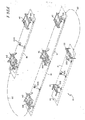
- a train 10 as illustrated in Figure 1 includes a plurality of cars 12, 14, 16 and 18 of different styles for purpose of illustration.
- Car 12 is a two-axle car, cars 14 and 16 are articulated cars sharing a common axle and car 18 is a conventional car having two axles per truck.
- a brake pipe 20 extends throughout the train 10.
- Each of the cars include a brake system which for car 12 is a single axle brake 22 and for cars 14, 16 and 18 are double axle brake systems 24.
- Included at each truck 22 and 24 is a triple valve 100 incorporating the principles of the invention.
- modulation valve systems 300 are also spread throughout the train at approximately 75 foot intervals.
- the twin axle brake 24, as shown in Figure 2, consists of a pair of brake beams 30, 32 and a single actuator 34 equipped with double-acting slack adjuster 36 and cable 38 operated parking brake.
- the actuator 34 is supported by, and lies along side, beam 30 and operates to spread a pair of bell cranks 40, whose ends are attached so as to drive the opposite brake beam 32 against its wheels.
- the pivot points of the bell cranks 40 in the master beam 30 react to the equal and opposite force generated by this action which pushes the master beam up against its wheels.
- the 17" total available stroke of the actuator is sufficient to permit the beams to mount 2-1 ⁇ 2" brake shoes and to operate without adjustment through the life of these shoes and through a full cycle of wheel wear.
- the combined reservoir and triple valve 100 is designed to be mounted to the truck bolster and connected with armored hoses 42 and 44 to both the brake actuator and the brake pipe respectively.
- the triple valve is comprised of three die castings and includes: a simple triple valve to produce service brake cylinder pressure, an emergency equalizing valve to provide high brake cylinder pressure in emergency, and an inshot valve to produce rapid filling of the actuator followed by a controlled brake cylinder pressure rise, which should be particularly important in an emergency brake application.
- the triple valve 100 brake equipment includes an optional empty load fixture 200, as shown in Figure 2. Because of the location of the basic triple valve portion of the truck bolster, the empty load fixture can be added by simply replacing a blanking plate with the additional portion as shown in the figure.
- the empty load portion has a load arm 202, which can be connected to, or rest upon, the truck frame spring basket so as to detect empty or loaded condition by the height of the bolster relative to this basket. Since this dimension is unaffected by centerplate or side bearing wear or truck swiveling, it provides a reliable, repeatable measure of spring deflection and, therefore, car load.
- the empty load fixtures operate on the proportioning principle, except that the dummy reservoir is on the high pressure rather than the low pressure side of the proportioning valve, resulting in its volume having to be only 69 cu. in., which volume is easily enclosed in the empty load portion itself.
- the brake pipe modulation group 300 in Figure 3, consists of an E-1 modulation valve 302 and KM-2 vent valve 304 mounted to the ends of a 10 x 20 release reservoir 306.
- the functions of this valve are to provide all of the brake pipe stabilizing and accelerating features of both the service and emergency portions of the present ABDW control valve. In particular, the following are carried out:
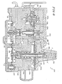
- the triple valve 100 as illustrated in Figure 4 includes three devices: the "A" triple valve 102, the "B" emergency equalizing valve 104 and a brake cylinder inshot valve 106.
- Positions of the triple valve are release and charging, service, service lap and emergency.
- During both service and emergency brake application there is both a first and second stage of brake cylinder pressure development controlled by the inshot valve 106.
- a third stage of development increased brake cylinder pressure by approximately 15% above full service.
- brake pipe air from the brake pipe enters triple valve 102, through passage 14 to Chamber A, moving the valve stem 121 downward and flows through Passage 112 to equalizing reset piston, Chamber C, and through Passage 113 to the underside of the emergency reservoir charging check 122. Air flowing through this check 122 and Passage 114 charges the 150 cu. in. emergency reservoir and flows by Passage 114a to the emergency equalizing valve spool 123 where it is blocked.
- Pilot Pin 125 raises the auxiliary reservoir charging check 126 from its seat, permitting brake pipe air to flow from Chamber A through the open charging check 126 and the hollow stem of the triple valve piston 124 into Chamber B, below the triple piston 124, from whence it flows through Passage 116 into Chamber E to the lower face of the emergency equalizing valve piston 132 holding this valve in its upper position. From Chamber E, air flows through Passage 115 to the emergency equalizing valve spool 123 and simultaneously through Passage 115b to the 650 cu. in. auxiliary reservoir.
- brake pipe pressure reduction in Chamber A will cause the triple valve stem 121 to move upward, unseating the supply valve 127 from its outer seat and connecting auxiliary reservoir pressure from Chamber G past the supply valve seat to Passage 118, through which it flows to the top of the open inshot valve check 128, through this valve to Chamber H, thence, through Passage 119 and the empty load blanking plate 129 to brake cylinder.
- Brake cylinder air is also fed back through Passage 119a to Chamber F above the emergency equalizing valve 104.
- inshot valve 106 is a variable flow rate valve allowing high flow during the initial stage of brake pressure build-up and a low flow rate in the latter stages.
- brake cylinder feedback pressure in Chamber F will reduce through Passage 119a along with brake cylinder.
- a modification to the triple valve could be made in which further travel of the triple valve downward would lead to a retarded recharge position on cars near the head of the train.
- the 650 cu. in. auxiliary reservoir takes so little charging air that this may not be necessary.
- Chamber J is connected to atmosphere through Choke Y and the small hole 135 through the center of the equalizing valve stem 123 to Chamber K beneath the spool 127, opening 137, and Chamber D above the emergency equalizing valve return piston 133.
- Motion of the emergency equalizing valve stem 123 to its lower seat cuts off communication via Passage 115 of auxiliary reservoir to brake cylinder and the hollow 123a of the emergency equalizing valve stem 123.
- this hollow stem 123a of 123 is connected to the emergency reservoir providing passage of air to the brake cylinder from the emergency reservoir.
- emergency reservoir air flows through the hollow 123a of stem 123 of the equalizing valve to Passage 117, thence, past the open supply valve to Passage 118, and through Choke Z of the inshot valve check 128 to the brake cylinder, adding a third or high pressure phase to brake cylinder pressure development.
- brake cylinder pressure With the brake applied in emergency, brake cylinder pressure, with an initial 70 psi brake pipe, would be 60 psi; auxiliary reservoir pressure would be 50 psi (lower than brake cylinder because of the emergency equalizing valve).
- auxiliary reservoir pressure would be 50 psi (lower than brake cylinder because of the emergency equalizing valve).
- the brake pipe need only be restored to something above 50 psi to raise the pressure in Chamber A above the auxiliary reservoir pressure in Chamber B.
- This reduced brake pipe pressure requirement, along with the dumpback of air from the modulating valve 300 should overcome the need for the present accelerated emergency release feature.
- the triple valve piston 124 moves down, it unseats its hollow spool 131 from the inner seat of the supply valve 127, permitting brake cylinder air to flow from brake cylinder to Passage 119 back through the inshot check valve 128, unseating this check 128, through Passages 118a and 118 and past the inner seat of the supply valve 127 to atmosphere through the hollow center 131 of the triple valve piston.
- Charging of the 650 cu. in. auxiliary reservoir will begin when sufficient differential of brake pipe pressure over auxiliary reservoir pressure exists to open the charging check 126 in the triple valve stem, and charging of the 150 cu. in. emergency reservoir will resume when auxiliary reservoir pressure has been restored above 60 psi so that pressure can flow from Passage 2 through Chamber C and the emergency reservoir charging check 122 to recharge this 150 cu. in. volume.
- the empty load blanking plate 129 shown in Figure 4 may be removed and the empty load device 200 shown diagrammatically in Figure 5 is mounted to it with the load arm 202 connected to the car as shown in Figure 2.
- This valve contains a simple ratioing valve 204, lock over piston 206, change over valve 208 and dummy volume 210, as shown in Figure 5, and operates in the following manner:
- brake cylinder pressure enters from the triple valve in Passage 221 and flows to Chamber A on the left side of the ratio valve. Simultaneously, air flows through Passage 211a to the semi-circular area 208a on top of the change over valve key 208.
- the load arm 202 will be positioned downward; and brake cylinder air will flow from Passage 211a past the key 208 to Passage 213, thence to Chamber C on the right hand side of the lock over piston 206.
- Chamber D on the left hand side of lock over piston 206 is vented to atmosphere by area 208b on the change over valve key 208. Moving this piston 206 to the left requires only 5 psi or less; and in its left most position, the piston is detented by an annular spring 207 engaging a detent groove 209a.
- Air also flows from Chamber A through Passage 211b and the unseated dummy volume cut-off check valve 230 into Passage 212 and the dummy volume 210. Since the dummy volume 210 is only 69 cu. in., this volume will accept the additional air supplied by the triple valve and not needed by the brake cylinder at the lower pressure of the ratio valve 204, thus, bringing about an equal reduction in auxiliary reservoir pressure in response to brake pipe pressure reduction whether the car is empty or loaded. Thus, at final equalization in either service or emergency, the output pressure of the triple valve in Passage 211 will be exactly the same, whether the car is loaded or empty. Brake cylinder pressure, however, whether service or emergency, will be 50, 60 or 70% of that provided by the triple valve as determined by the ratio of Chamber A area to Chamber B area.
- brake cylinder air from Chamber B also flows through 214a to the face of bypass check valve 232 but cannot open this valve because of the higher supply pressure behind it, from 211c which holds it to its seat.
- change over key valve 208 will rotate causing lock over piston 206 to move right opening bypass check valve 232 and allow dummy volume cut-off check 230 to close.
- This allows the brake cylinder pressure at 214 to equalize and reduce with the supply from the triple valve at 211 via the bypass paths.
- Dummy volume cut-off check 230 responsive to the reduction of pressure in passage 211b, opens to equalize and reduce the pressure in dummy volume 210.
- the dummy volume cut-off check 230 which is permitted to move to its seat by the lock over piston 206, will do so and prevent unnecessary loss of air to the dummy volume 210.
- E-1 brake pipe modulating valve 302 shown in Figure 3 and diagrammatically in Figure 6, is to provide quick service propagation of an initial service application and to provide a continuous quick service function.
- a third purpose is to control the storage and release back to brake pipe of air in a release volume so as to provide accelerated release of brakes after both service and emergency brake applications.
- E-1 brake pipe modulating valve 302 The only connection to the E-1 brake pipe modulating valve 302 is to the brake pipe and the augmentation of brake pipe pressure change it provides will be comparable to those in the AB, ABD and ABDW type control valves.
- brake pipe pressure in Passage 316 also flows through Passage 316a to Choke Z and to the face of release reservoir control check 326 through Passage 316b.
- Brake pipe air flows through Choke Z into Passage 318 and the underside of the accelerated release check 328, thence past this check 328 into Passage 319 whence it charges the release reservoir and through Passage 319a to Chamber F above the quick service limiting valve piston 330.
- pipe pressure may be reduced to initiate a brake application.
- a reduction is begun simultaneous reduction of pressure in Chambers A, C and E occurs.
- No motion of the quick service limiting valve 332 will occur because it is held up by a 3 psi differential spring 334 in Chamber G.
- the accelerated release valve piston 320 will initially be resting on the stabilizing spring cage 336, having permitted the accelerated release check 328 to close at the termination of release reservoir 306 charging.
- the accelerated release valve piston 320 will not move down until the brake pipe pressure drops about 1 ⁇ 2 psi and will not move down until the stabilizing spring has been overcome. When this occurs, the accelerated release valve diaphragm piston 320 will move down opening the quick service check valve 338.
- accelerated application pilot valve piston 322 also moves down forcing its check 324 from its seat and permitting quick action chamber 308 air to flow from Passage 317a past the open check valve 324 to atmosphere through Choke U, while subjecting the inner area of the accelerated application valve diaphragm 342 to the pressure backed up by Choke U.
- accelerated release valve piston 320 Whenever brake pipe pressure rises above quick action chamber pressure in Chamber B by more than a predetermined amount, accelerated release valve piston 320 will be moved upward and unseat the accelerated release check 328. This action will dump accelerated release volume 306 back to brake pipe, aiding in the restoration of brake pipe pressure by way of Passage 319, past the open accelerated release check 328, Passage 318 and 318a, through the release control check 326 bypassing Choke Z, into Passage 316a and 316b, Chamber A, and out Passage 311 to the brake pipe. At the same time, the motion of the accelerated release valve piston 320 upward allows the quick service check 338 to seat, preventing the exhaustion of brake pipe air when the quick service limiting valve 332 returns to its upper position.
Landscapes
- Engineering & Computer Science (AREA)
- Transportation (AREA)
- Mechanical Engineering (AREA)
- Physics & Mathematics (AREA)
- Fluid Mechanics (AREA)
- Braking Systems And Boosters (AREA)
- Valves And Accessory Devices For Braking Systems (AREA)
Abstract
Description
- The present invention relates generally to pneumatic rail brake systems and more specifically to improved components for the system.
- The prior art brake systems were generally standardized to include an ABD or equivalent braking valve connected by conduits to the brake pipe, auxiliary and emergency reservoirs and brake cylinders. These brake valves would control all the brakes on the trucks of a single car. If more than two trucks were to be controlled by the same brake valve, relay valves were included. These systems include a substantial amount of conduits connecting the elements of the brake system on each of the cars. The ABD and equivalent brake valves include the service application, emergency application, release and accelerated release function. With the development of non-conventional car designs, brake systems which are adaptions of the preexisting brake systems were developed. These and the conventional brake systems include an unnecessary amount of conduits per car and unnecessarily large reservoirs.
- According to the present invention there is provided a brake control system for a train of cars comprising:
- (a) brake pipe means secured to car bodies throughout a train of cars for selectively designating brake application and release signals by the selective charging and discharging of the brake pipe with fluid,
- (b) braking equipment for at least one car of a train of cars selectively responsive to changes of pressure in the brake pipe comprising:
- (1) truck brake control means for at least one truck of each car, having pneumatic control connections to the brake pipe only on the car body, for governing braking of the associated truck, and
- (c) modulation control means, independent of any truck brake control means, having pneumatic control connections to the brake pipe only on the car body, for sensing changes in pressure in the brake pipe and for locally assisting in propagation of such pressure changes through the brake pipe.
- According to a further aspect of the invention there is provided a modulating valve to be connected to a brake pipe characterized by brake pipe and atmosphere ports, a quick service volume, a bulb volume, a release reservoir, sensing means connected to said brake pipe port for sensing a service signal, release signal and an emergency signal pressures on said brake pipe port, and valve means connected to said brake pipe port, atmosphere port, said quick service volume, said release reservoir and said sensing means for filling said quick service volume with fluid from said brake pipe port for a service signal sensed by said sensing means, for sequentially venting said bulb volume to said atmosphere port and refilling said bulb volume from said brake pipe port as a function of the magnitude of the service signal sensed by said sensing means, and for charging said brake pipe port with fluid from said release reservoir for a release signal sensed by said sensing means.
- According to a still further aspect of the invention there is provided a brake system for a train having a plurality of cars, each car including at least one truck, characterized in that said brake system includes a brake pipe, a plurality of brake cylinders, one on each truck, a plurality of pairs of auxiliary and emergency reservoirs, one pair for each truck, a plurality of triple valve means, one for each truck, connected to said brake pipe, brake cylinder and auxiliary and emergency reservoirs for receiving service application, emergency application and release signals on said brake pipe and providing brake applications to said brake cylinder from said reservoirs and releasing said brake cylinder in response to a respective received signal, and a plurality of modulating means, less than the number of trucks, connected along said brake pipe for accelerating said signals down said brake pipe.
- A triple valve assembly is provided which has reduced auxiliary and emergency reservoirs mounted directly thereon. The assembly is connected only to the brake pipe and to the brake cylinder of one truck and controls the interconnection between the brake pipe, brake cylinder, auxiliary reservoir and emergency reservoir to produce charging of the reservoirs, service application and emergency application of the brakes and release of air to the brake cylinder. The unique triple valve, in response to the venting of brake pipe which characterizes an emergency brake application, provides a sequential application of pressure to the brake cylinders. First the auxiliary reservoir pressure is equalized with that of the brake cylinder, followed by disconnection of the auxiliary reservoir from an application of the emergency reservoir to the brake cylinder. This sequential operation allows increased brake cylinder pressure while allowing reduction in the volume of the emergency reservoir used to accomplish this pressure.
- In both service and emergency applications, a variable flow rate valve is connected between the supply portion of the triple valve and the brake cylinder to allow a high flow during the initial application of the air to the brake cylinder with a decreased flow rate during the second stage.
- The triple valve assembly is easily adaptable for receiving a load responsive fixture. This fixture includes a first path for connecting the supply to the brake cylinder and to a volume reservoir and providing a predetermined portion of supply pressure to the brake cylinder. A second path controlled by the load is connected in parallel with the first path, and bypasses the proportioning path and cuts off the volume reservoir for a loaded sensed condition. A double acting piston is provided to simultaneously open the bypass and close the dummy reservoir or connect the dummy reservoir and close the bypass. The bypass is also responsive to a brake released signal to bypass the proportioning device during a brake release sequence.
- A modulating valve is also provided independent of the triple valve assemblies, which enhances brake pipe pressure reduction by filling a quick service volume with fluid from the brake pipe for a service signal, and sequentially venting a bulb volume to the atmosphere and refills the bulb volume from the brake pipe as a function of the magnitude of the service signal. The modulating valve also charges the brake pipe with previously stored fluid so as to enhance the rise of brake pipe pressure, hence release of the brakes from a release reservoir in response to a release signal. The filling of the quick service volume occurs at a rate controlled as a function of the differential pressure between the release reservoir and the brake pipe. A quick action chamber is included for providing accelerated response for filling the quick service volume and venting the bulb volume. The quick action chamber is vented after the accelerated initiation and has no effect during further brake pipe pressure reduction activity.
- The present invention will be described in conjunction with the accompanying drawings, in which,
- Figure 1 is a schematic perspective of a train brake system made up of different types of cars.
- Figure 2 is a perspective view of a truck mounted brake incorporating the valve and reservoir of the present invention.
- Figure 3 is a perspective view of the modulation valve of the present invention.
- Figure 4 is a cross-section of the supply valve of the present invention.
- Figure 5 is a cross-sectional view of the load fixture incorporating the principles of the present invention.
- Figure 6 is a cross-sectional view of the modulation valve incorporating the principles of the present invention.
- A
train 10 as illustrated in Figure 1 includes a plurality ofcars Car 12 is a two-axle car,cars car 18 is a conventional car having two axles per truck. Abrake pipe 20 extends throughout thetrain 10. Each of the cars include a brake system which forcar 12 is asingle axle brake 22 and forcars axle brake systems 24. Included at eachtruck triple valve 100 incorporating the principles of the invention. Also spread throughout the train at approximately 75 foot intervals aremodulation valve systems 300. Thus, it can be seen that a braking valve is included at each truck irrespective of the truck and car design. - The
twin axle brake 24, as shown in Figure 2, consists of a pair ofbrake beams single actuator 34 equipped with double-actingslack adjuster 36 andcable 38 operated parking brake. Theactuator 34 is supported by, and lies along side,beam 30 and operates to spread a pair ofbell cranks 40, whose ends are attached so as to drive theopposite brake beam 32 against its wheels. The pivot points of thebell cranks 40 in themaster beam 30 react to the equal and opposite force generated by this action which pushes the master beam up against its wheels. - The 17" total available stroke of the actuator is sufficient to permit the beams to mount 2-½" brake shoes and to operate without adjustment through the life of these shoes and through a full cycle of wheel wear.
- The combined reservoir and
triple valve 100, as shown in Figure 2, is designed to be mounted to the truck bolster and connected witharmored hoses - In connection with the triple valve portion, it should be noted that no release insuring quick service or emergency brake pipe related functions are included. When brake pipe pressure reduces to zero, the triple valve reacts by raising the brake cylinder pressure approximately 15% higher than the value attained at full service equalization. This will be described in detail below with respect to Figure 4.
- To provide cars having high gross-to-tare weight ratios with a more even braking ratio over the entire load range, the
triple valve 100 brake equipment includes an optionalempty load fixture 200, as shown in Figure 2. Because of the location of the basic triple valve portion of the truck bolster, the empty load fixture can be added by simply replacing a blanking plate with the additional portion as shown in the figure. The empty load portion has aload arm 202, which can be connected to, or rest upon, the truck frame spring basket so as to detect empty or loaded condition by the height of the bolster relative to this basket. Since this dimension is unaffected by centerplate or side bearing wear or truck swiveling, it provides a reliable, repeatable measure of spring deflection and, therefore, car load. - In operation, the empty load fixtures operate on the proportioning principle, except that the dummy reservoir is on the high pressure rather than the low pressure side of the proportioning valve, resulting in its volume having to be only 69 cu. in., which volume is easily enclosed in the empty load portion itself.
- The brake
pipe modulation group 300, in Figure 3, consists of anE-1 modulation valve 302 and KM-2vent valve 304 mounted to the ends of a 10 x 20release reservoir 306. The functions of this valve are to provide all of the brake pipe stabilizing and accelerating features of both the service and emergency portions of the present ABDW control valve. In particular, the following are carried out: - a) The quick service function detects brake pipe pressure reductions beyond a fixed amount and opens brake pipe to a quick service volume so as to produce rapid serial transmission of service application and assure a minimum brake pipe reduction.
- b) An accelerated application valve provides continuous quick service activity for brake pipe reduction at a service rate beyond quick service.
- c) An accelerated release valve provides a dumpback to brake pipe of the 1600 cu. in. release volume, any time brake pipe pressure rises more than a fixed amount, whether as a result of service or emergency release. There is no accelerated release after emergency because the 318 cu. in. of air stored in the two actuators on a typical car would provide a negligible improvement in brake pipe release when compared with the 1256 cu. in. available on a 10 x 12 cylinder at 8" piston travel.
- d) Rapid transmission of emergency brake application from any cause is propagated solely by the KM-2 vent valve portion.
- The
triple valve 100 as illustrated in Figure 4 includes three devices: the "A"triple valve 102, the "B"emergency equalizing valve 104 and a brake cylinder inshot valve 106. - Positions of the triple valve are release and charging, service, service lap and emergency. During both service and emergency brake application, there is both a first and second stage of brake cylinder pressure development controlled by the inshot valve 106. In emergency, a third stage of development increased brake cylinder pressure by approximately 15% above full service.
- Operation of the equipment for each of the above positions is as detailed below.
- In the release and charging position, brake pipe air from the brake pipe enters
triple valve 102, throughpassage 14 to Chamber A, moving thevalve stem 121 downward and flows through Passage 112 to equalizing reset piston, Chamber C, and throughPassage 113 to the underside of the emergencyreservoir charging check 122. Air flowing through thischeck 122 andPassage 114 charges the 150 cu. in. emergency reservoir and flows by Passage 114a to the emergency equalizingvalve spool 123 where it is blocked. Note that when thetriple valve piston 124 moves downward,Pilot Pin 125 raises the auxiliary reservoir charging check 126 from its seat, permitting brake pipe air to flow from Chamber A through theopen charging check 126 and the hollow stem of thetriple valve piston 124 into Chamber B, below thetriple piston 124, from whence it flows throughPassage 116 into Chamber E to the lower face of the emergency equalizingvalve piston 132 holding this valve in its upper position. From Chamber E, air flows throughPassage 115 to the emergency equalizingvalve spool 123 and simultaneously through Passage 115b to the 650 cu. in. auxiliary reservoir. - With both reservoirs charged, pressure across the
triple valve piston 124 will equalize; and it will move upward allowing the chargingcheck 126 to close cutting off communication between the brake pipe and auxiliary reservoir. This is the release lap position of thetriple valve 102. - Note that with the
emergency equalizing valve 104 in its upper position, air fromPassage 115 passes upward through the hollow 123a ofstem 123 of this valve throughPassage 117 to Chamber G of the closed brake cylinder supply valve of thetriple valve 102. - During a service application of brakes, brake pipe pressure reduction in Chamber A will cause the
triple valve stem 121 to move upward, unseating thesupply valve 127 from its outer seat and connecting auxiliary reservoir pressure from Chamber G past the supply valve seat toPassage 118, through which it flows to the top of the openinshot valve check 128, through this valve to Chamber H, thence, through Passage 119 and the emptyload blanking plate 129 to brake cylinder. - Brake cylinder air is also fed back through
Passage 119a to Chamber F above theemergency equalizing valve 104. - As brake cylinder pressure continues to build up during a second stage of a service or emergency application, it passes through Chamber H of the open
inshot valve check 128. When sufficient air has flowed into the brake cylinder to raise its pressure to approximately 15 psi, the diaphragm piston 130 of Chamber H moves down allowing the inshot valve check 128 to close. Further build up of brake cylinder pressure is under the control of Choke Z. Thus, inshot valve 106 is a variable flow rate valve allowing high flow during the initial stage of brake pressure build-up and a low flow rate in the latter stages. - As air flows from the auxiliary reservoir to the brake cylinder, the pressure in Chamber B, beneath the triple valve,
piston 124 falls until it nearly equals that of Brake Pipe in Chamber A, at which point thevalve stem 121 will move downward and allow thesupply valve 127 to close on its outer seat. This will prevent the supply of further auxiliary reservoir air to brake cylinder and, hence, terminate the reduction of pressure in the auxiliary reservoir and Chamber B, placing thevalve 127 in service lap position. - With the
supply valve 127 initially in the service lap position, any increase in brake pipe pressure will cause the pressure in Chamber A to rise above Chamber B, which will pull thetriple valve stem 121 down away from thesupply valve 127, opening the inner seat and permitting brake cylinder air to flow back through theinshot check valve 128, opening it, hence, throughPassage stem 121 of thetriple valve 102 to atmosphere. - Simultaneously with the above, brake cylinder feedback pressure in Chamber F will reduce through
Passage 119a along with brake cylinder. - Note that reduction of brake cylinder pressure in this manner does not upset the balance of brake pipe pressure over auxiliary reservoir, and the
triple valve 102 remains in its release position until brake cylinder pressure reduces to zero. - Note also that if the brake pipe pressure is only slightly higher than auxiliary reservoir, the
supply valve 127 inner seat will be open; but because of the length of the auxiliary reservoir charging checkvalve pilot pin 125, the chargingcheck 126 will remain on its seat preventing premature charging of the auxiliary reservoir and, thus, assuring that no air will be trapped in the brake cylinder. Only when a slightly greater pressure exists in the brake pipe than in auxiliary reservoir will thetriple valve stem 121 be forced downward sufficiently to open the chargingvalve 126. - A modification to the triple valve could be made in which further travel of the triple valve downward would lead to a retarded recharge position on cars near the head of the train. However, the 650 cu. in. auxiliary reservoir takes so little charging air that this may not be necessary.
- In an emergency brake application, brake pipe pressure is suddenly reduced to zero.
Triple valve 102 action is identical with that described above under service brake application, and a 15 lb. inshot of air to the brake cylinder will be made prior to closing of theinshot valve check 128, as in service. From the point of closing of the inshot valve check 128 until brake cylinder pressure rises to within 2 psi of auxiliary reservoir pressure, brake cylinder pressure development is affected only by thetriple valve 102 andinshot valve check 128. Note, however, that when brake pipe pressure is reduced to zero in the emergency application, pressure in Chamber C beneath the emergency equalizingvalve return piston 133 is also reduced to zero, allowing the spring in Chamber D of thisdiaphragm piston 133 to move it down so that it no longer holds up the emergency equalizingvalve stem 123. Theemergency equalizing valve 123 will, however, be held up by the differential of auxiliary reservoir in Chamber E over brake cylinder pressure in Chamber F. - When brake cylinder pressure in Chamber F rises to within 2 psi of auxiliary reservoir pressure in Chamber E, the emergency equalizing
valve stem 123 will begin to move downward under the influence ofemergency spring 134 in Chamber J. Chamber J is connected to atmosphere through Choke Y and the small hole 135 through the center of the equalizingvalve stem 123 to Chamber K beneath thespool 127, opening 137, and Chamber D above the emergency equalizingvalve return piston 133. When the emergency equalizingvalve stem 123 begins to move downward, supply valve air inPassage 117 flows upward throughPassage 117a; and at the first motion of theemergency equalizing spool 123 downward,Passage 117a is connected to Chamber J past the upper land of the emergency equalizingvalve spool 123, causing auxiliary reservoir pressure present inPassage 117 to vent into Chamber J where it acts on the top of the emergency equalizingvalve stem 123 urging it rapidly downward. Since Choke Y is much smaller than thepassage 117a admitting this air to Chamber J, pressure developing in Chamber J assures full motion of theemergency equalizing spool 123 downward until its motion is stopped by therubber seat 136 at the bottom of Chamber K. - When the emergency equalizing valve rests on this
seat 136, communication through Choke Y to atmosphere throughopenings 137 is blocked and brake cylinder pressure is maintained in Chamber F, where along withSpring 134, it continues to hold theemergency equalizing valve 123 downward against itslower seat 136. - Motion of the emergency equalizing
valve stem 123 to its lower seat cuts off communication viaPassage 115 of auxiliary reservoir to brake cylinder and the hollow 123a of the emergency equalizingvalve stem 123. In its lower position, this hollow stem 123a of 123 is connected to the emergency reservoir providing passage of air to the brake cylinder from the emergency reservoir. Thus, using emergency reservoir air only to increase brake cylinder pressure and not wasting it by needlessly increasing auxiliary reservoir pressure as in earlier components with the emergency equalizing valve in its lower position, emergency reservoir air flows through the hollow 123a ofstem 123 of the equalizing valve toPassage 117, thence, past the open supply valve toPassage 118, and through Choke Z of the inshot valve check 128 to the brake cylinder, adding a third or high pressure phase to brake cylinder pressure development. - With the brake applied in emergency, brake cylinder pressure, with an initial 70 psi brake pipe, would be 60 psi; auxiliary reservoir pressure would be 50 psi (lower than brake cylinder because of the emergency equalizing valve). Thus, when brakes are released, the brake pipe need only be restored to something above 50 psi to raise the pressure in Chamber A above the auxiliary reservoir pressure in Chamber B. This reduced brake pipe pressure requirement, along with the dumpback of air from the modulating
valve 300 should overcome the need for the present accelerated emergency release feature. - As with service release, when the
triple valve piston 124 moves down, it unseats itshollow spool 131 from the inner seat of thesupply valve 127, permitting brake cylinder air to flow from brake cylinder to Passage 119 back through theinshot check valve 128, unseating thischeck 128, throughPassages supply valve 127 to atmosphere through thehollow center 131 of the triple valve piston. - This action reduces brake cylinder pressure at a rate independent of inshot choke Z. As brake cylinder pressure reduces, so does the pressure in Chamber F above the
emergency equalizing valve 132. At the same time this pressure is being reduced, pressure in Chamber C, beneath the emergency equalizingvalve return piston 133, is acting to force the emergency equalizing valve 3 upward to its service position. When the brake cylinder pressure in Chamber F above the emergency equalizingvalve piston 132 drops to the point where the combined effort of auxiliary reservoir pressure in Chamber E and return piston pressure in Chamber C are sufficient to urge it upward, it will begin to move upward and will cut off communication through Passage 17a to Chamber J allowing Chamber J pressure to reduce to atmosphere through Choke Y, assuring that once theemergency equalizing valve 123 has started to move upward, this motion will be continued to its upper most stop and the release position. Finally, when brake cylinder pressure drops below 15 psi, this pressure acting in Chamber G will no longer be sufficient to keep the inshot valve piston 130 down and will allow this piston 130 to move up, aiding the back flow of air to keeping open the inshot valve check 128 and assuring complete release of brake cylinder air to the atmosphere. - Charging of the 650 cu. in. auxiliary reservoir will begin when sufficient differential of brake pipe pressure over auxiliary reservoir pressure exists to open the charging
check 126 in the triple valve stem, and charging of the 150 cu. in. emergency reservoir will resume when auxiliary reservoir pressure has been restored above 60 psi so that pressure can flow from Passage 2 through Chamber C and the emergency reservoir charging check 122 to recharge this 150 cu. in. volume. - In the event that an empty
load brake system 200 is required, the emptyload blanking plate 129 shown in Figure 4 may be removed and theempty load device 200 shown diagrammatically in Figure 5 is mounted to it with theload arm 202 connected to the car as shown in Figure 2. This valve contains asimple ratioing valve 204, lock overpiston 206, change overvalve 208 anddummy volume 210, as shown in Figure 5, and operates in the following manner: - When a brake application is made, brake cylinder pressure enters from the triple valve in Passage 221 and flows to Chamber A on the left side of the ratio valve. Simultaneously, air flows through
Passage 211a to thesemi-circular area 208a on top of the change overvalve key 208. In the event that the car is light, theload arm 202 will be positioned downward; and brake cylinder air will flow fromPassage 211a past the key 208 toPassage 213, thence to Chamber C on the right hand side of the lock overpiston 206. Chamber D on the left hand side of lock overpiston 206 is vented to atmosphere by area 208b on the change overvalve key 208. Moving thispiston 206 to the left requires only 5 psi or less; and in its left most position, the piston is detented by anannular spring 207 engaging a detent groove 209a. - As air pressure continues to rise in the supply pressure in Chamber A on the left hand side of the
ratio valve 204 exerts less force on the spool of thisvalve 204 than does the brake cylinder pressure in Chamber B on its right hand side, forcing the double piston spool to the left against the ratio valve seat at a ratio of 50, 60 or 70% of input pressure, as determined by the particular diaphragms used. As supply pressure from the triple valve continues to rise, Chamber A pressure will build up, forcing the spool to the right, allowing further passage of air through the hollow spool to Chamber B causing it, again to close, with Chamber B pressure always at the desired ratio to Chamber A pressure. - Air also flows from Chamber A through
Passage 211b and the unseated dummy volume cut-offcheck valve 230 intoPassage 212 and thedummy volume 210. Since thedummy volume 210 is only 69 cu. in., this volume will accept the additional air supplied by the triple valve and not needed by the brake cylinder at the lower pressure of theratio valve 204, thus, bringing about an equal reduction in auxiliary reservoir pressure in response to brake pipe pressure reduction whether the car is empty or loaded. Thus, at final equalization in either service or emergency, the output pressure of the triple valve inPassage 211 will be exactly the same, whether the car is loaded or empty. Brake cylinder pressure, however, whether service or emergency, will be 50, 60 or 70% of that provided by the triple valve as determined by the ratio of Chamber A area to Chamber B area. - Note that during the above light car operation, brake cylinder air from Chamber B also flows through 214a to the face of
bypass check valve 232 but cannot open this valve because of the higher supply pressure behind it, from 211c which holds it to its seat. However, if the car becomes heavier after an initial light load application and before release, change overkey valve 208 will rotate causing lock overpiston 206 to move right openingbypass check valve 232 and allow dummy volume cut-off check 230 to close. This allows the brake cylinder pressure at 214 to equalize and reduce with the supply from the triple valve at 211 via the bypass paths. Dummy volume cut-off check 230, responsive to the reduction of pressure inpassage 211b, opens to equalize and reduce the pressure indummy volume 210. - When brake cylinder pressure is released, air flows from Chamber A out to the triple valve, through the triple valve, and to atmosphere causing the
ratio valve 204 to close more tightly to its seat. However, air from brake cylinder inPassage 214 can flow through Chamber B, throughPassage 214a, and will unseat the bypass check 232 because of its differential over the now reduced supply pressure inPassage 211c. Thus, during release, brake cylinder pressure flows from brake cylinder intoPassage 214, through Chamber B,Passage 214a, past thebypass check valve 232, unseating it, intoPassage 211c,Passage 211b, Chamber A, and outPassage 211 to the triple valve and exhaust. Since dummy cut-off check 230 is held open by lock overpiston 206, thedummy reservoir 210 is also emptied viapassage 211b, etc. - If the car weighs heavy, the
load arm 202 will be moved upward andPassage 211a will be connected through the changeover valve key area 208b toPassage 215. Supply air will, thus, enter Chamber D on the left side of the lock overpiston 206, forcing it to the right, in which position it will be detented bydetent spring 207 andgroove 209b, forcing the bypass check 232 off of its seat and allowing the dummy volume cut-off check 230 to move to its seat. - As air pressure builds up in
Passage 211 and Chamber A where, again, it flows through the hollow piston rod of theratio valve 204 to chamber B and the brake cylinder and, again, forces the ratio valve to the left. However, with the lock overpiston 206 in its right hand position, air can flow from Chamber A throughPassages Passage 214, Chamber B, and out to the brake cylinder. - Since the
dummy volume 212 is not desired cut in, as all air supplied by the triple valve in the loaded position must be passed to the brake cylinder, the dummy volume cut-off check 230, which is permitted to move to its seat by the lock overpiston 206, will do so and prevent unnecessary loss of air to thedummy volume 210. - When brakes are released after an application with the empty load fixtures in the loaded position, air flow out of the valve is exactly the same as in the empty position with the exception that brake cylinder pressure does not have to move the bypass check 232 off of its seat as it is held open by the lock over
piston 206 in any case. - The purpose of the E-1 brake
pipe modulating valve 302 shown in Figure 3 and diagrammatically in Figure 6, is to provide quick service propagation of an initial service application and to provide a continuous quick service function. A third purpose is to control the storage and release back to brake pipe of air in a release volume so as to provide accelerated release of brakes after both service and emergency brake applications. - The only connection to the E-1 brake
pipe modulating valve 302 is to the brake pipe and the augmentation of brake pipe pressure change it provides will be comparable to those in the AB, ABD and ABDW type control valves. - When charging this
valve 302, air flows initially from brake pipe bypassage 311 to the underside of accelerated release valve piston 320, Chamber A, thence throughPassage 316 to Chamber C on the underside of accelerated applicationpilot valve piston 322. Air from Chamber C flows through Quick Action Chamber Charging Choke Y andPassage 317 to thequick action chamber 308, andPassage 317a to the back of the accelerated application pilotvalve check valve 324. Air flowing through Choke Y is at quick action chamber pressure and is communicated viaPassage 317b to Chamber D, above the accelerated applicationpilot valve piston 322 and Chamber B, above the accelerated release valve piston 320. - Note that brake pipe pressure in
Passage 316 also flows through Passage 316a to Choke Z and to the face of release reservoir control check 326 through Passage 316b. Brake pipe air flows through Choke Z intoPassage 318 and the underside of the acceleratedrelease check 328, thence past thischeck 328 intoPassage 319 whence it charges the release reservoir and throughPassage 319a to Chamber F above the quick service limitingvalve piston 330. - With the equipment fully charged, pipe pressure may be reduced to initiate a brake application. When such a reduction is begun simultaneous reduction of pressure in Chambers A, C and E occurs. No motion of the quick
service limiting valve 332 will occur because it is held up by a 3 psi differential spring 334 in Chamber G. The accelerated release valve piston 320 will initially be resting on the stabilizingspring cage 336, having permitted the acceleratedrelease check 328 to close at the termination ofrelease reservoir 306 charging. The accelerated release valve piston 320 will not move down until the brake pipe pressure drops about ½ psi and will not move down until the stabilizing spring has been overcome. When this occurs, the accelerated release valve diaphragm piston 320 will move down opening the quickservice check valve 338. When the quickservice check valve 338 is moved off its seat, brake pipe air will flow to thequick service volume 340; and because of the proximity of thequick service check 338 to Chamber A, this flow will cause a further downward motion of the accelerated release valve piston 320, thus, assuring that thequick service check 338 will open wide, permitting brake pipe pressure to flow from brake pipe throughPassage 311, Chamber A, Passage 312, past the openquick service check 338 to the quick service limitingvalve spool 332, hence, into thequick service volume 340. - Initial flow of air will be rapid enough to propagate this quick service action to the next car and will terminate when a 3 psi differential of release reservoir pressure over brake pipe pressure is established, which differential will move the quick service limiting
valve spool 332 down cutting off further communication with brake pipe through thequick service check 338. - At this same time, accelerated application
pilot valve piston 322 also moves down forcing itscheck 324 from its seat and permittingquick action chamber 308 air to flow fromPassage 317a past theopen check valve 324 to atmosphere through Choke U, while subjecting the inner area of the acceleratedapplication valve diaphragm 342 to the pressure backed up by Choke U. - If this backed up pressure is sufficient, it will cause the accelerated
application diaphragm 342 to move downward from its seat exposing the larger outer area and permitting the upper accelerated application check valve toseat 344, cutting off communication between brake pipe in Passage 312 and the already chargedbulb volume 346. As long as the acceleratedapplication pilot valve 322 is down permittingquick action chamber 308 air to flow to Atmosphere, the acceleratedapplication valve piston 342 will be held down by air acting over its full upper diaphragm face, and will drain thebulb volume 346 throughPassage 314 and itslower check valve 348. Whenquick action chamber 308 pressure reduction exceeds that of the brake pipe, the accelerated applicationpilot valve piston 322 will rise, allowing itscheck 324 to close and cut off the supply ofquick action chamber 308 air to the acceleratedapplication valve piston 342 which will allow its upper chambers to drain through Chokes U and T. This action will allow the acceleratedapplication valve piston 342 to move upward, returning itslower check 348 to its seat to prevent further draining of thebulb volume 346 and reopening itsupper check 344, thus, reconnecting the drainedbulb volume 346 to brake pipe causing a controlled volume of air to be withdrawn from it, thus, causing a further reduction of brake pipe pressure by allowing Passage 312 to communicate past theupper check 344 to Passage 313 and through Choke V with the now drainedbulb volume 346. After quick service activity has terminated, any time brake pipe pressure is reduced, the accelerated applicationpilot valve piston 324 will, again, move down triggering this sequence of events much the same way the accelerated application valve operates on the present ABDW emergency AAV portion. - Whenever brake pipe pressure rises above quick action chamber pressure in Chamber B by more than a predetermined amount, accelerated release valve piston 320 will be moved upward and unseat the accelerated
release check 328. This action will dump acceleratedrelease volume 306 back to brake pipe, aiding in the restoration of brake pipe pressure by way ofPassage 319, past the open acceleratedrelease check 328,Passage 318 and 318a, through the release control check 326 bypassing Choke Z, into Passage 316a and 316b, Chamber A, and outPassage 311 to the brake pipe. At the same time, the motion of the accelerated release valve piston 320 upward allows thequick service check 338 to seat, preventing the exhaustion of brake pipe air when the quickservice limiting valve 332 returns to its upper position. As brake pipe pressure recharges and accelerated release reservoir air pressure decreases, the differential of Chamber A over Chamber B in the accelerated release valve will be decreased; and when brake pipe pressure is less than 5 psi, higher than accelerated release check 328 pressure, the acceleratedrelease check 328 spring will return thischeck valve 328 to its seat and the E-1 brakepipe modulating valve 302 will be returned to its fully charged position. Above this pressure, brake pipe pressure can only be supplied from the locomotive; and when a further 3 psi has been built up in the brake pipe, its pressure will be higher than accelerated release reservoir pressure and acceleratedrelease reservoir 306 recharge will begin through Choke Z and the accelerated releasereservoir charging check 328. - From the preceding description of the preferred embodiments, it is evident that the objects of the invention are attained in that reduced size reservoirs are mounted directly to the triple valve which are mounted on each truck. The accelerated application and release functions are separate from the triple valve and are distributed through the train.
Claims (11)
(1) truck brake control means for at least one truck of each car, having pneumatic control connections to the brake pipe only on the car body, for governing braking of the associated truck, and
(b) accelerated application pilot valve means for sensing a service application signal in the brake pipe and thereby permitting fluid from a quick action chamber to flow past a check valve opened by the pilot valve to atmosphere through an atmospheric choke, and
(b) accelerated application valve means having means for sensing fluid pressure in a passage between the quick action chamber and the atmospheric choke for closing the normally open check valve means and opening another check valve means to permit the bulb volume fluid to be exhausted, thus completing a cycle of continuous quick service cycle control means.
Applications Claiming Priority (3)
| Application Number | Priority Date | Filing Date | Title |
|---|---|---|---|
| US06/776,763 US4653812A (en) | 1985-09-16 | 1985-09-16 | Truck mounted pneumatic brake control system |
| US776763 | 1985-09-16 | ||
| EP86307135A EP0261282B1 (en) | 1985-09-16 | 1986-09-16 | Truck mounted pneumatic brake control system |
Related Parent Applications (1)
| Application Number | Title | Priority Date | Filing Date |
|---|---|---|---|
| EP86307135.3 Division | 1986-09-16 |
Publications (2)
| Publication Number | Publication Date |
|---|---|
| EP0351890A2 true EP0351890A2 (en) | 1990-01-24 |
| EP0351890A3 EP0351890A3 (en) | 1990-05-09 |
Family
ID=25108301
Family Applications (2)
| Application Number | Title | Priority Date | Filing Date |
|---|---|---|---|
| EP86307135A Expired - Lifetime EP0261282B1 (en) | 1985-09-16 | 1986-09-16 | Truck mounted pneumatic brake control system |
| EP89116671A Withdrawn EP0351890A3 (en) | 1985-09-16 | 1986-09-16 | Brake control system for railway cars |
Family Applications Before (1)
| Application Number | Title | Priority Date | Filing Date |
|---|---|---|---|
| EP86307135A Expired - Lifetime EP0261282B1 (en) | 1985-09-16 | 1986-09-16 | Truck mounted pneumatic brake control system |
Country Status (7)
| Country | Link |
|---|---|
| US (1) | US4653812A (en) |
| EP (2) | EP0261282B1 (en) |
| AU (1) | AU599042B2 (en) |
| CA (1) | CA1264789A1 (en) |
| DE (1) | DE3681166D1 (en) |
| MX (1) | MX160744A (en) |
| ZA (1) | ZA866100B (en) |
Families Citing this family (24)
| Publication number | Priority date | Publication date | Assignee | Title |
|---|---|---|---|---|
| US4726628A (en) * | 1986-11-28 | 1988-02-23 | General Signal Corporation | Protection valve device for spring parking brake systems |
| US5118166A (en) * | 1991-05-06 | 1992-06-02 | Westinghouse Air Brake Company | Quick service function for railway freight brake control valve device |
| US5211450A (en) * | 1991-09-12 | 1993-05-18 | Knorr Brake Holding Corporation | Empty/load valve |
| US5400874A (en) * | 1993-09-10 | 1995-03-28 | Knorr Brake Holding Corp. | Single actuator truck mount brake system |
| US5551766A (en) * | 1994-10-11 | 1996-09-03 | Ellcon National, Inc. | Empty/load sensor mechanism for controlled vehicle braking |
| US6176354B1 (en) | 1997-06-13 | 2001-01-23 | New York Air Brake Corporation | Truck mounted brake beam with removable brake heads |
| US5947236A (en) * | 1997-06-13 | 1999-09-07 | New York Air Brake Corporation | Truck mounted brake for standard and premium ride trucks |
| US6332515B1 (en) | 1997-06-13 | 2001-12-25 | New York Air Brake Corp. | Truck mounted brake beam |
| US5984426A (en) * | 1997-07-31 | 1999-11-16 | Westinghouse Air Brake Company | Apparatus and method for a railway freight car brake control |
| US6186284B1 (en) | 1998-09-17 | 2001-02-13 | New York Air Brake Corp. | Fluid parking brake for a rail vehicle air brake cylinder |
| US6264288B1 (en) * | 1999-07-02 | 2001-07-24 | Miner Enterprises, Inc. | Brake system for rail cars |
| US6698552B2 (en) | 2000-09-14 | 2004-03-02 | New York Air Brake Corporation | Parking brake for a rail vehicle |
| US6375278B1 (en) | 2000-12-20 | 2002-04-23 | New York Air Brake Corporation | Hydraulic parking brake |
| US6648424B2 (en) | 2002-03-29 | 2003-11-18 | New York Air Brake Corporation | Brake system with graduated empty/load |
| US7306295B2 (en) * | 2003-03-05 | 2007-12-11 | New York Air Brake Corporation | Pump system for parking brakes for a rail vehicle |
| US7249659B2 (en) * | 2004-01-08 | 2007-07-31 | New York Air Brake Corporation | Fluid actuator |
| US9623855B2 (en) * | 2004-01-08 | 2017-04-18 | New York Air Brake Llc | Parking brake system including a brake cylinder |
| SE536138C2 (en) * | 2011-04-26 | 2013-05-28 | Faiveley Transport Nordic Ab | bogie brake assembly |
| RU2510345C1 (en) * | 2012-07-16 | 2014-03-27 | Федеральное государственное бюджетное образовательное учреждение высшего профессионального образования "Дальневосточный государственный университет путей сообщения" (ДВГУПС) | Car braking system |
| FR2999133B1 (en) * | 2012-12-10 | 2015-02-20 | Faiveley Transp Amiens | PNEUMATIC BRAKE DISTRIBUTOR FOR RAILWAY VEHICLE |
| FR2999134B1 (en) * | 2012-12-10 | 2015-02-20 | Faiveley Transp Amiens | PNEUMATIC BRAKE DISTRIBUTOR FOR RAILWAY VEHICLE |
| US20150056048A1 (en) * | 2013-03-15 | 2015-02-26 | Tracy Miller | Adjustable and stowable train cargo lift system and method |
| RU2535364C2 (en) * | 2013-03-27 | 2014-12-10 | Федеральное государственное бюджетное образовательное учреждение высшего профессионального образования "Дальневосточный государственный университет путей сообщения" (ДВГУПС) | Railway vehicle brake |
| US10232865B2 (en) * | 2015-07-29 | 2019-03-19 | Westinghouse Air Brake Technologies Corporation | Truck mounted brake system for rod-under style bolsters |
Citations (2)
| Publication number | Priority date | Publication date | Assignee | Title |
|---|---|---|---|---|
| DE1809513A1 (en) * | 1967-11-21 | 1969-07-24 | Westinghouse Air Brake Co | Device for controlling an independent pressure medium source on a special railway car |
| US4093315A (en) * | 1977-07-05 | 1978-06-06 | Page W R | Modulating valve assembly for railroad car brake cylinders |
Family Cites Families (12)
| Publication number | Priority date | Publication date | Assignee | Title |
|---|---|---|---|---|
| US2734783A (en) * | 1956-02-14 | safford | ||
| US3160446A (en) * | 1961-10-30 | 1964-12-08 | Westinghouse Air Brake Co | Railway brake control valve device |
| US3208801A (en) * | 1962-07-13 | 1965-09-28 | Westinghouse Air Brake Co | Railway brake control system with optional direct or graduated release feature |
| US3175871A (en) * | 1963-10-11 | 1965-03-30 | Westinghouse Air Brake Co | Continual quick service valve device |
| US3570529A (en) * | 1969-10-13 | 1971-03-16 | Gen Signal Corp | Emergency vent valve |
| CA1268503A (en) * | 1970-09-28 | 1990-05-01 | Thomas H. Engle | Empty load brake |
| US3671086A (en) * | 1970-12-16 | 1972-06-20 | Westinghouse Air Brake Co | Empty-load changeover apparatus |
| US3716276A (en) * | 1971-10-27 | 1973-02-13 | Westinghouse Air Brake Co | Quick service valve device |
| ZA775595B (en) * | 1976-10-13 | 1978-07-26 | Gen Signal Corp | Fluid brake control system |
| US4188071A (en) * | 1978-06-19 | 1980-02-12 | Westinghouse Air Brake Company | Railway vehicle brake apparatus arranged to accommodate reduced emergency reservoir volume |
| US4441764A (en) * | 1981-01-14 | 1984-04-10 | General Signal | Relay valve assembly |
| US4509801A (en) * | 1983-11-18 | 1985-04-09 | General Signal Corporation | Fluid pressure brake control systems for freight locomotives |
-
1985
- 1985-09-16 US US06/776,763 patent/US4653812A/en not_active Expired - Lifetime
-
1986
- 1986-08-13 ZA ZA866100A patent/ZA866100B/en unknown
- 1986-08-19 AU AU61603/86A patent/AU599042B2/en not_active Ceased
- 1986-08-27 CA CA000516913A patent/CA1264789A1/en active Granted
- 1986-09-12 MX MX3728A patent/MX160744A/en unknown
- 1986-09-16 DE DE8686307135T patent/DE3681166D1/en not_active Expired - Lifetime
- 1986-09-16 EP EP86307135A patent/EP0261282B1/en not_active Expired - Lifetime
- 1986-09-16 EP EP89116671A patent/EP0351890A3/en not_active Withdrawn
Patent Citations (2)
| Publication number | Priority date | Publication date | Assignee | Title |
|---|---|---|---|---|
| DE1809513A1 (en) * | 1967-11-21 | 1969-07-24 | Westinghouse Air Brake Co | Device for controlling an independent pressure medium source on a special railway car |
| US4093315A (en) * | 1977-07-05 | 1978-06-06 | Page W R | Modulating valve assembly for railroad car brake cylinders |
Also Published As
| Publication number | Publication date |
|---|---|
| AU599042B2 (en) | 1990-07-12 |
| AU6160386A (en) | 1987-03-19 |
| ZA866100B (en) | 1987-03-25 |
| CA1264789A1 (en) | 1990-01-23 |
| EP0261282A1 (en) | 1988-03-30 |
| DE3681166D1 (en) | 1991-10-02 |
| MX160744A (en) | 1990-05-09 |
| CA1269124C (en) | 1990-05-15 |
| EP0261282B1 (en) | 1991-08-28 |
| EP0351890A3 (en) | 1990-05-09 |
| US4653812A (en) | 1987-03-31 |
Similar Documents
| Publication | Publication Date | Title |
|---|---|---|
| US4653812A (en) | Truck mounted pneumatic brake control system | |
| CA2351915C (en) | Apparatus and method for pneumatically controlled graduated brake pressure release for freight train brake system | |
| JP2670425B2 (en) | Brake control device for locomotive | |
| US4775194A (en) | Pneumatically operated graduated release valve for rail vehicles | |
| US5429427A (en) | Air brake control valve with combined graduated and direct release | |
| US3910639A (en) | Commuter car brake systems | |
| US4611858A (en) | Hydraulic brake system | |
| CA1238932A (en) | Fluid pressure brake control systems for freight locomotives | |
| US4405182A (en) | Control valve arrangement for combined brake cylinder and air reservoir device | |
| AU624150B2 (en) | Pneumatic rail brake systems | |
| CA1269125A (en) | Vehicle load responsive valve | |
| EP1273498B1 (en) | Apparatus and method for pneumatically controlled graduated brake pressure release for freight train brake system | |
| US4441764A (en) | Relay valve assembly | |
| JPH06104441B2 (en) | Automatic Modulator Device for Servo Break | |
| US4498712A (en) | Empty/load brake control arrangement | |
| US4073544A (en) | Continual quick service valve device | |
| US4421360A (en) | Relay valve assembly | |
| GB2133096A (en) | Preventing wheel lock during braking | |
| US3910641A (en) | Brake system for an articulated carrier | |
| CA2558723C (en) | Apparatus and method for pneumatically controlled graduated brake pressure release for freight train brake system | |
| US2490998A (en) | Control apparatus for controlling brake cylinder pressure | |
| US4095850A (en) | Brake control valve apparatus | |
| KR200218033Y1 (en) | Apparatus for rapidly releasing a brake of train | |
| JPH044179B2 (en) | ||
| CA1199666A (en) | Relay valve assembly |
Legal Events
| Date | Code | Title | Description |
|---|---|---|---|
| PUAI | Public reference made under article 153(3) epc to a published international application that has entered the european phase |
Free format text: ORIGINAL CODE: 0009012 |
|
| AC | Divisional application: reference to earlier application |
Ref document number: 261282 Country of ref document: EP |
|
| AK | Designated contracting states |
Kind code of ref document: A2 Designated state(s): CH DE FR GB IT LI |
|
| RIN1 | Information on inventor provided before grant (corrected) |
Inventor name: ENGLE, THOMAS H. |
|
| PUAL | Search report despatched |
Free format text: ORIGINAL CODE: 0009013 |
|
| AK | Designated contracting states |
Kind code of ref document: A3 Designated state(s): CH DE FR GB IT LI |
|
| RHK1 | Main classification (correction) |
Ipc: B60T 15/36 |
|
| 17P | Request for examination filed |
Effective date: 19901029 |
|
| RAP1 | Party data changed (applicant data changed or rights of an application transferred) |
Owner name: KNORR BRAKE HOLDING CORPORATION |
|
| 17Q | First examination report despatched |
Effective date: 19920702 |
|
| STAA | Information on the status of an ep patent application or granted ep patent |
Free format text: STATUS: THE APPLICATION IS DEEMED TO BE WITHDRAWN |
|
| 18D | Application deemed to be withdrawn |
Effective date: 19930928 |