EP0351465B1 - Ankerbolzen - Google Patents
Ankerbolzen Download PDFInfo
- Publication number
- EP0351465B1 EP0351465B1 EP88306706A EP88306706A EP0351465B1 EP 0351465 B1 EP0351465 B1 EP 0351465B1 EP 88306706 A EP88306706 A EP 88306706A EP 88306706 A EP88306706 A EP 88306706A EP 0351465 B1 EP0351465 B1 EP 0351465B1
- Authority
- EP
- European Patent Office
- Prior art keywords
- bar
- rolls
- lobes
- section
- thread
- Prior art date
- Legal status (The legal status is an assumption and is not a legal conclusion. Google has not performed a legal analysis and makes no representation as to the accuracy of the status listed.)
- Expired - Lifetime
Links
- 239000011435 rock Substances 0.000 title claims description 52
- 230000015572 biosynthetic process Effects 0.000 claims description 18
- 238000005755 formation reaction Methods 0.000 claims description 18
- 239000002184 metal Substances 0.000 claims description 14
- 238000000034 method Methods 0.000 claims description 12
- 238000004519 manufacturing process Methods 0.000 claims description 7
- 238000005097 cold rolling Methods 0.000 claims description 2
- 239000000463 material Substances 0.000 description 16
- 229910000831 Steel Inorganic materials 0.000 description 4
- 239000010959 steel Substances 0.000 description 4
- 239000003054 catalyst Substances 0.000 description 3
- 238000003754 machining Methods 0.000 description 3
- 230000002093 peripheral effect Effects 0.000 description 3
- 238000005096 rolling process Methods 0.000 description 3
- 238000004873 anchoring Methods 0.000 description 2
- 239000011159 matrix material Substances 0.000 description 2
- 239000012260 resinous material Substances 0.000 description 2
- 239000002775 capsule Substances 0.000 description 1
- 230000001419 dependent effect Effects 0.000 description 1
- 238000006073 displacement reaction Methods 0.000 description 1
- 230000000694 effects Effects 0.000 description 1
- 239000011440 grout Substances 0.000 description 1
- 238000010438 heat treatment Methods 0.000 description 1
- 238000005098 hot rolling Methods 0.000 description 1
- 238000005065 mining Methods 0.000 description 1
- 239000002245 particle Substances 0.000 description 1
- 230000003014 reinforcing effect Effects 0.000 description 1
- 239000007787 solid Substances 0.000 description 1
Images

Classifications
-
- B—PERFORMING OPERATIONS; TRANSPORTING
- B21—MECHANICAL METAL-WORKING WITHOUT ESSENTIALLY REMOVING MATERIAL; PUNCHING METAL
- B21B—ROLLING OF METAL
- B21B1/00—Metal-rolling methods or mills for making semi-finished products of solid or profiled cross-section; Sequence of operations in milling trains; Layout of rolling-mill plant, e.g. grouping of stands; Succession of passes or of sectional pass alternations
- B21B1/16—Metal-rolling methods or mills for making semi-finished products of solid or profiled cross-section; Sequence of operations in milling trains; Layout of rolling-mill plant, e.g. grouping of stands; Succession of passes or of sectional pass alternations for rolling wire rods, bars, merchant bars, rounds wire or material of like small cross-section
- B21B1/163—Rolling or cold-forming of concrete reinforcement bars or wire ; Rolls therefor
-
- B—PERFORMING OPERATIONS; TRANSPORTING
- B21—MECHANICAL METAL-WORKING WITHOUT ESSENTIALLY REMOVING MATERIAL; PUNCHING METAL
- B21H—MAKING PARTICULAR METAL OBJECTS BY ROLLING, e.g. SCREWS, WHEELS, RINGS, BARRELS, BALLS
- B21H3/00—Making helical bodies or bodies having parts of helical shape
- B21H3/02—Making helical bodies or bodies having parts of helical shape external screw-threads ; Making dies for thread rolling
-
- E—FIXED CONSTRUCTIONS
- E04—BUILDING
- E04C—STRUCTURAL ELEMENTS; BUILDING MATERIALS
- E04C5/00—Reinforcing elements, e.g. for concrete; Auxiliary elements therefor
- E04C5/08—Members specially adapted to be used in prestressed constructions
- E04C5/12—Anchoring devices
- E04C5/125—Anchoring devices the tensile members are profiled to ensure the anchorage, e.g. when provided with screw-thread, bulges, corrugations
-
- E—FIXED CONSTRUCTIONS
- E21—EARTH OR ROCK DRILLING; MINING
- E21D—SHAFTS; TUNNELS; GALLERIES; LARGE UNDERGROUND CHAMBERS
- E21D21/00—Anchoring-bolts for roof, floor in galleries or longwall working, or shaft-lining protection
- E21D21/008—Anchoring or tensioning means
Definitions
- This invention relates to a rock bolt and more particularly, but not exclusively, to a rock bolt for use in underground mining operations.
- rock bolts are used to secure rock strata underground.
- One kind comprises a length of reinforcing bar having ribs along its length.
- the ribs enhance the anchoring ability of the bolt.
- the bolt is usually rotated in the hole to mix the settable material and the ribs also serve the purpose of assisting the mixing of the settable material.
- known ribbed formations on rock bolts do not provide good mixing characteristics.
- the end of the bolt which is intended to project from the rock face has a rolled thread thereon which receives a nut used to tension the bolt.
- the bar from which such a prior art rock bolt is made is manufactured in a steel mill and is supplied with the ribs formed on the whole length of the bar.
- the bolt has to be machined to remove the ribs on a section thereof and to ensure that such section has a circular cross-section. Such a machining operation adds to the cost of the prior art rock bolt.
- Japanese Application JP-A-59-113948 describes a method of manufacturing an anchor bolt using round bar having a smooth outer peripheral face and an outer diameter corresponding to a specified effective diameter of thread.
- the bar is cut to a specified length and a specified thread is worked by form-rolling on the outer peripheral face of an end of the bar to form the threaded part.
- a specified rugged pattern is worked by form-rolling on the outer peripheral face of another end of the bar to form the basal part.
- an anchor bolt having an unworked linear part between the basal part and threaded part is manufactured.
- pitch diameter in relation to a straight thread, means the diameter of an imaginary co-axial cylinder, the surface of which passes through the thread profiles at such points as to make the width of the groove equal to one half of the basic pitch of the thread. On a perfect thread this occurs at the point where the width of the thread and groove are equal.
- bar when used in this specification includes a pipe and a bar with an axial bore.
- a method of making a rock bolt having a smooth section with a thread formed thereon and a further section on which protrusions are formed by passing the bolt between a pair of rolls comprising the steps of; providing a metal bar of circular or near circular cross-section having a diameter which is substantially equal to the pitch diameter of the thread to be formed thereon; cold forming a series of flat lobes spaced from one another in staggered formation on opposite sides of the bar along a selected section of the bar by passing the bar in a single pass through a pair of rolls, the rolls defining a nip between them and having formations provided at predetermined positions along their peripheries, the rolls being rotated in opposite directions so that a formation on one roll coincides periodically with a formation on the other roll in the nip of the rolls, the bar being fed lengthwise through the nip of the rolls so that the formations pinch the metal of the bar to form said flat lobes along said selected section thereof; displacing one or
- This method obviates the need for machining the bar before forming the thread thereon. As will become evident in the subsequent description, the method also results in a saving of material without reducing the yield or tensile load-carrying ability of the rock bolt.
- the metal bar is first cut to a discrete length, is then advanced through means forming the series of protrusions on the selected section of the bar, and is thereafter advanced through straightening means to straighten it, whereafter thread is formed on the further selected section of the bar.
- a continuous length of the metal bar is first advanced through means forming the series of protrusions on selected sections of the bar, the continuous length is thereafter advanced through straightening means to straighten it, whereafter the bar is cut to required lengths and thread is formed on a selected section of each length.
- the protrusions are formed on the bar by pinching the metal of the bar at intervals along the length of the selected section of the bar.
- the sides of each lobe thus provided nearest and furthest the axis of the bar may be arcuate so that each lobe has a generally elliptical outline.
- the protrusions may be formed on substantially the entire length of the bar, save for the selected section on which the thread is formed.
- Apparatus for performing the method according to the invention of making a rock bolt from a metal bar may comprise a pair of rolls, means for driving the rolls about their axes in opposite directions, each roll having a channel formed in its surface facing the other roll, the channels defining a passage for receiving the metal bar in lengthwise fashion, each rolls having formations providing along its periphery which align periodically with similar formations on the other roll in the nip of the rolls when they are rotated in opposite directions, characterised in that the rolls are displaceable towards and away from one another to permit the formations on the rolls to pinch the metal of the bar along only a selected section of the bar as it passes between the rolls.
- the apparatus may include means for straightening the bar after it has been passed between the rolls.
- the means for straightening the bar may comprise two sets of opposed staggered rolls through which the bar is passed, the rollers of one set being located at right angles to those of the other set.
- the formations on the rolls may be in the form of pegs mounted on the rolls.
- the rock bolt made according to the method of the invention can be of any required length and the selected section carrying the protrusions normally will be longer than 1 meter.
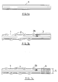
- a rock bolt according to the invention is formed from a steel bar 1 of circular or near circular cross-section.
- the first step in making a rock bolt from the bar 1 is to form a series of protrusions in the form of flat lobes 2 in the bar by a method which will be more fully described hereunder.
- a section 3 of the bar which is to be threaded is left free of lobes 2.
- a thread 4 is cold rolled on to the section 3 of the bar.
- the pitch diameter of the thread 4 is indicated by numeral 5 and is substantially equal to the diameter of the bar.
- the lobes 2 are arranged in staggered formation along the length of the bar 1.
- the sides 2a, 2b of each lobe respectively nearest and furthest the axis of the bar are arcuate so that each lobe has a generally elliptical outline in plan view.
- the thread 4 may first be rolled onto the section 3 of the bar after which the lobes 2 may be formed on the remainder of the bar. Thereafter the bar may be straightened.
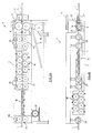
- the apparatus indicated generally by numeral 6, comprises a frame 7 having a pair of rolls 8, 9 mounted thereon for rotation about horizontal axes.
- An electric motor 10 is provided to drive the rolls about their respective axes in opposite directions.
- the drive is effected through a pulley 11 and a suitable gear train (not shown).
- the rolls 8, 9 are mounted in such a manner that they can selectively be displaced towards and away from one another. This may conveniently be effected by hydraulic means (not shown).
- the rolls 8, 9 have grooves 12, 13 formed respectively in their edges facing one another, which grooves define a passage for receiving the bar 1 in lengthwise fashion (Figure 3a).
- Each roll has a plurality of pegs 14 mounted thereon along its periphery.
- the pegs 14 are arranged in such a manner that corresponding pegs on the rolls periodically align in the nip of the rolls when they are rotated.
- the pegs 14 are preferably of cirular cross-section but they may be of any required cross-section depending on the shape of the lobes 2 required on the bar 1.
- the bar 1 is cut to a discrete length and is fed through a pair of guide rollers 21 into the nip of the rolls 8, 9 while the rolls are driven in opposite directions.
- the pegs 9 periodically pinch the metal of the bar 1 to form the lobes 2 therein. This is achieved in a single pass of the bar 1 through the rolls 8, 9 in the cold condition of the bar.
- the lobes 2 are not shown on the bar 1 in Figures 2a and 2b. They are, however, shown in Figures 3a and 3d.
- the rolls 8, 9 are controlled to ensure that the lobes 2 are formed only on a selected section of the bar. In this embodiment of the invention this is achieved by means of a pair of sensing devices 22, 23 mounted ahead of and behind the rolls 8, 9.
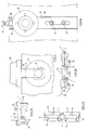
- the sensing device 23 mounted behind the rolls 8, 9 comprises a support 24 carrying a retractable stop member 25 and a sensor 26 ( Figure 3b).
- the support 24 also carries two pairs of dependent guides 27, 28 through which the bar 1 moves.
- the sensing device 22 mounted ahead of the rolls 8, 9 may be the same as the sensing device 2, 3 but the retractable stop member 25 may be omitted.
- the bar 1 With the rolls 8, 9 in an open position, the bar 1 is advanced freely therebetween. As the leading end of the bar enters the sensing device 23 located behind the rolls 8, 9 the sensor 26 of the device 23 causes the stop member 25 to retract and causes the rolls 8, 9 to close and to commence rotating. The bar 1 advances further through the rolls 8, 9 as the lobes 2 are formed thereon and as the trailing end of the bar leaves the sensing device 22, the rolls 8, 9 are caused by the sensor of the device 22 to open and to cease rotation.
- the sensing devices 22, 23 are adjustable in the direction of the path of the bar 1 and hence the sections of the bar which are free of lobes 2 and which carry lobes 2 can be selected by forward and rearward adjustment of the sensing devices 22, 23.
- the driven rollers 15, 17 and 19 serve to advance the bar 1 along its path through the apparatus 6.
- pneumatic heads 29 are provided which carry the upper rollers in the sets.
- Each head 29 has a dependant rod 30 which connects to a mounting 31 which carries the associated roller 16 and which is slidable in a guide 32 ( Figure 3c).
- rollers 16 As the bar passes between the straightening rollers 16 it is straightened in a vertical plane and as it passes between the straightening rollers 18 it is straightened in a horizontal plane.
- the rollers 18 have central channels 33 formed therein to accommodate the lobes 2 on the bar as it passes between the rollers ( Figure 3d).
- each of the straightening rollers 16, 18 is adjustable towards and away from its opposing rollers to enable its effect on the bar 1 to be varied.
- each straightening roller 16, 18 is mounted on a slide 34 which is slidable in a guide 35 and is adjustable by means of a setting bolt 36 ( Figure 3e).
- the slide 34 is secured by lock nuts 37, 38.
- the rollers, 16, 18 will be so adjusted that a flexing of the bar 1 takes place as it passes between the rollers.
- the thread 4 is rolled onto a selected section of the bar in conventional manner.
- a chute 39 is positioned beneath the rolls 8, 9 to collect scale generated by the action of the rolls on the bar 1.
- the manner of forming the lobes 2 on the bar 1 described above is relatively simple and inexpensive and the apparatus 7 can maintain speeds of the bar 1 passing therethrough of at least 35m/min.
- the lobes 2 are formed in a single plane but if desired they can be formed in two or more planes.
- a continuous length of the bar 1 may be fed through the apparatus shown in Figures 2a to 2b.
- the rolls 8, 9 are periodically displaced away from and towards one another to ensure that the lobes 2 are formed only on consecutive selected sections of the bar.
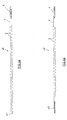
- FIGs 4a and 4b two rock bolts made according to the invention are shown.
- the rock bolt 40 shown in Figure 4a is intended for embedding in a settable resinous material mixed with a catalyst. It has thread 4 formed at one end thereof to receive a nut (not shown). At its other end it has a chamfered point 41 which is used to rupture a capsule of the settable material (not shown) located in the hole in the rock matrix in which the bolt is to be embedded.
- the rock bolt 42 shown in Figure 4b is similar to the one shown in Figure 4a but instead of the point 41 it has a thread 43.
- the thread 43 is used to connect the rock bolt to a conventional mechanical anchor (not shown) which expands when the rock bolt is tensioned to anchor it in a hole.
- a mechanical anchor not shown
- settable resinous material or concrete can be used to grout the rock bolt 42 in the hole.
- a rock bolt made according to the invention is to be embedded in a settable material mixed with a catalyst
- the rock bolt will, in use, be rotated about its axis to assist in mixing of the settable material.
- the lobes 2 on the bolt will in such a case assist considerably in mixing the settable material by causing lateral displacement of the settable material during rotation of the bolt.
- any particle situated adjacent the bolt between two lobes 2 will be displaced by the lobe on the opposite side of the bolt when it is rotated.
- the improved mixing ability of the bolt arises from the fact that with the use of the lobes 2, the diameter of the bolt at the apices of opposed lobes can be as much as 1,5 times the diameter of the bolt.
- the rock bolt described above provides a continuously changing perimeter along its length and this in itself enhances its mixing ability in use.
- the lobes 2 will also assist in the anchoring of the bolt in settable material.
- the rock bolt of the invention provides a continuously changing perimeter along its length
- the provision of the lobes 2 thereon does not materially alter its cross-section along its length. This means that the provision of the lobes does not result in a sacrifice of cross-section and hence does not affect the tensile strength of the rock bolt.
- the machining or shaving step in the prior art method described above is dispensed with.
- a substantial saving of material can be obtained with a rock bolt made according to the invention, when regard is had to the following.
- the diameter of the ribbed section of the prior art rock bolt is larger than the diameter (e) thereof. Yet this larger diameter does not increase the tensile strength of the prior art bolt, since the tensile strength is determined by the minimum diameter of the thread (f).
- the prior art rock bolt therefore carries excess material over the length of its ribbed section. In the rock bolt made according to the invention, such excess material is limited since the diameter of the bar 1 is in the first place chosen to equal the pitch diameter of the thread 4. In this way a saving of material of up to 25% can be achieved compared with a prior art rock bolt, which results in a less expensive rock bolt when made according to the method of the invention.
- the load capacity of the anchorage provided by a rock bolt embedded in a settable material such as concrete is proportional to the perimeter of the bolt.
- the perimeter of the bar 1 may be increased before, during or after the operation in which the lobes 2 are formed in the bar. This may be done, for example, by changing the cross-section of the bar in the lobe forming operation from a circular to an elliptical shape.
- the rock bolt of the invention formed in this way from a bar of smaller cross-section than that of a conventional rock bolt, can provide the same anchorage capacity as the conventional rock bolt.
- the rock bolt of the invention can also be made from pipe or metal bar with an axial bore, for use in applications where settable material is injected through the rock bolt itself. Also, any part of the rock bolt of the invention may be left free of lobes 2, if required.
- the invention has particular application to rock bolts which are provided in lengths in which the lobed section is longer than 1 metre.
Landscapes
- Engineering & Computer Science (AREA)
- Mechanical Engineering (AREA)
- Architecture (AREA)
- Structural Engineering (AREA)
- Mining & Mineral Resources (AREA)
- Civil Engineering (AREA)
- Life Sciences & Earth Sciences (AREA)
- General Life Sciences & Earth Sciences (AREA)
- Geochemistry & Mineralogy (AREA)
- Geology (AREA)
- Forging (AREA)
Claims (2)
- Ein Verfahren zur Herstellung eines Gesteinsankers mit einem glatten Abschnitt, an dem ein Gewinde (4) geformt ist, und einem weiteren Abschnitt, an dem Vorsprünge (2) durch Hindurchleiten des Gesteinsankers zwischen ein Paar Walzen (8, 9) geformt sind, umfassend die Schritte
der Erstellung einer Metallstange (1) mit kreisförmigem oder nahezu kreisförmigem Querschnitt und einem Durchmesser, der im wesentlichen dem Flankendurchmesser des daran zu formenden Gewindes gleich ist;
des Kaltformens einer Reihe von flachen Lappen (2), die entlang eines ausgewählten Abschnitts der Stange auf gegenüberliegenden Seiten der Stange in versetzter Anordnung in Abstand von einander angeordnet sind, indem die Stange in einem einzigen Gang durch ein Paar Walzen (8, 9) hindurchgeleitet wird, wobei die Walzen zwischen einander einen Walzenspalt abgrenzen und an vorbestimmten Positionen entlang ihrer Peripherien Gebilde (14) aufweisen, und zwar werden die Walzen in entgegengesetzten Richtungen rotiert, so daß ein Gebilde an einer Walze in dem Walzenspalt periodisch mit einem Gebilde an der anderen Walze zusammentrifft, wobei die Stange der Länge nach durch den Walzenspalt hindurchgeführt wird, so daß die Gebilde das Stangenmetall zusammenpressen, um die besagten flachen Lappen (2) entlang des besagten ausgewählten Abschnitts der besagten Stange zu formen;
des Wegbewegens zu einer vorbestimmten Zeit von mindestens einer der besagten Walzen (8, 9) von der anderen, um sicherzustellen, daß die besagten Lappen (2) nur an dem besagten ausgewählten Abschnitt der Stange geformt werden;
des Richtens der Stange in ihrem kalten Zustand in zwei Ebenen durch der Reihe nach Hindurchleiten der Stange durch zwei Walzensätze (16, 18), wobei die Walzen des einen Satzes im rechten Winkel zu denen des anderen Satzes angeordnet sind und die Walzen jedes Satzes in versetztem Gegenüberverhältnis angeordnet sind; und
des Kaltwalzens des Gewindes (4) mit dem besagten Flankendurchmesser an einem weiteren ausgewählten Abschnitt (3) der Stange, der keine der besagten Lappen (2) aufweist. - Ein Verfahren nach Anspruch 1, dadurch gekennzeichnet, daß die Lappen (2) außer an dem ausgewählten Abschnitt (3), an dem das Gewinde geformt wird, im wesentlichen entlang der gesamten Stangenlänge geformt werden.
Priority Applications (1)
| Application Number | Priority Date | Filing Date | Title |
|---|---|---|---|
| DE19883887326 DE3887326T2 (de) | 1988-07-21 | 1988-07-21 | Ankerbolzen. |
Applications Claiming Priority (2)
| Application Number | Priority Date | Filing Date | Title |
|---|---|---|---|
| ZA868649 | 1986-11-14 | ||
| ZA878529A ZA878529B (en) | 1986-11-14 | 1987-11-13 | Rock bolt |
Publications (2)
| Publication Number | Publication Date |
|---|---|
| EP0351465A1 EP0351465A1 (de) | 1990-01-24 |
| EP0351465B1 true EP0351465B1 (de) | 1994-01-19 |
Family
ID=27137658
Family Applications (1)
| Application Number | Title | Priority Date | Filing Date |
|---|---|---|---|
| EP88306706A Expired - Lifetime EP0351465B1 (de) | 1986-11-14 | 1988-07-21 | Ankerbolzen |
Country Status (3)
| Country | Link |
|---|---|
| EP (1) | EP0351465B1 (de) |
| AU (1) | AU604948B2 (de) |
| ZA (1) | ZA878529B (de) |
Families Citing this family (2)
| Publication number | Priority date | Publication date | Assignee | Title |
|---|---|---|---|---|
| US5054146A (en) * | 1988-12-08 | 1991-10-08 | Videx-Wire Products (Pty.) Limited | Anchor bolt |
| DE4137090A1 (de) * | 1991-11-12 | 1993-05-13 | Heinrich Liebig | Klebeanker |
Family Cites Families (8)
| Publication number | Priority date | Publication date | Assignee | Title |
|---|---|---|---|---|
| US2347904A (en) * | 1941-07-26 | 1944-05-02 | Gerald G Greulich | Method of cold-working metallic bars |
| US2911865A (en) * | 1957-01-17 | 1959-11-10 | United States Steel Corp | Apparatus for making formed wire |
| US3742747A (en) * | 1971-11-30 | 1973-07-03 | Nippon Concrete Ind Co Ltd | Method for shaping indented steel wire and apparatus therefor |
| CH604951A5 (en) * | 1976-08-11 | 1978-09-15 | Belloli Ferriere & Co | Concrete reinforcing anchorage rod with threaded ends |
| US4064729A (en) * | 1977-03-02 | 1977-12-27 | Alex Homery | Metal forming device |
| US4303354A (en) * | 1979-03-28 | 1981-12-01 | Peabody Coal Company | Mine roof bolting |
| AU523376B3 (en) * | 1980-08-22 | 1982-06-24 | Titan Manufacturing Co. Pty. Ltd., The | Production of a rolled thread onto a deformed bar |
| US4649729A (en) * | 1985-01-14 | 1987-03-17 | Florida Steel Corporation | Method for manufacturing steel bar with intermittent smooth surface and patterned relief segments, and mine roof bolt product |
-
1987
- 1987-11-13 ZA ZA878529A patent/ZA878529B/xx unknown
-
1988
- 1988-07-21 EP EP88306706A patent/EP0351465B1/de not_active Expired - Lifetime
- 1988-08-01 AU AU20227/88A patent/AU604948B2/en not_active Expired
Also Published As
| Publication number | Publication date |
|---|---|
| AU604948B2 (en) | 1991-01-03 |
| AU2022788A (en) | 1990-02-01 |
| EP0351465A1 (de) | 1990-01-24 |
| ZA878529B (en) | 1989-06-28 |
Similar Documents
| Publication | Publication Date | Title |
|---|---|---|
| US5054146A (en) | Anchor bolt | |
| US4953379A (en) | Hot-rolled steel bar with helically extending ribs, method of and apparatus for producing the steel bar | |
| US3533260A (en) | Rolling of metal billets | |
| US4955219A (en) | Rock bolt | |
| US4649729A (en) | Method for manufacturing steel bar with intermittent smooth surface and patterned relief segments, and mine roof bolt product | |
| EP0351465B1 (de) | Ankerbolzen | |
| EP0515802B1 (de) | Schraubennahtrohrwerk zum Herstellen von geschweissten Schraubennahtrohren aus Metallband | |
| US3503237A (en) | Fabrication of articles by rolling | |
| US8341991B2 (en) | Manufacturing method and manufacturing apparatus for twisted flat bar | |
| EP0194478A2 (de) | Vorrichtung zum Richten von Stäbe ohne eine um die Längsachse relative Verdrehung aufeinanderfolgender Materialsegmente | |
| CA2295287C (en) | Slitter for the purpose of multiple sections | |
| CA1317489C (en) | Rock bolt | |
| US4075880A (en) | Machine for continuously cold working steel bar | |
| EP1332011A1 (de) | Verfahren zum herstellen eines bandförmigen vormaterials, insbesondere aus metall, welches in aufeinanderfolgenden abschnitten profiliert ist, und eine vorrichtung dafür | |
| DE602004001281T2 (de) | Verfahren und Vorrichtung zum Abbremsen und zur vorübergehenden Speicherung warmgewalzter Produkte | |
| EP0442935B1 (de) | Felsenanker und verfahren zur herstellung | |
| EP2473296B1 (de) | Vorrichtung zur spanlosen bearbeitung langgestreckter werkstücke | |
| DE3887326T2 (de) | Ankerbolzen. | |
| DE3401595C2 (de) | ||
| CA1254487A (en) | Disc roller mechanism and method for forming helical shapes | |
| DE10134285C2 (de) | Verfahren zum Herstellen eines bandförmigen Vormaterials, insbesondere aus Metall, welches in aufeinanderfolgenden Abschnitten profiliert ist, und eine Vorrichtung dafür | |
| WO1985005577A1 (fr) | Procede et dispositif pour laminer une bande de metal | |
| EP1183117B1 (de) | Verfahren zum herstellen eines bandförmigen vormaterials aus metall, insbesondere eines solchen vormaterials welches in regelmässig wiederkehrenden abschnitten profiliert ist, und die verwendung einer vorrichtung dafür | |
| EP1019990B1 (de) | Verfahren zum herstellen eines kommutatorringes für einen kommutator sowie danach hergestellter kommutator | |
| DE19938966C1 (de) | Verfahren und Vorrichtung zum Herstellen eines bandförmigen Vormaterials aus Metall, insbesondere eines solchen Vormaterials welches in regelmäßig wiederkehrenden Abschnitten profiliert ist, und die Verwendung einer Vorrichtung dafür |
Legal Events
| Date | Code | Title | Description |
|---|---|---|---|
| PUAI | Public reference made under article 153(3) epc to a published international application that has entered the european phase |
Free format text: ORIGINAL CODE: 0009012 |
|
| AK | Designated contracting states |
Kind code of ref document: A1 Designated state(s): BE DE FR GB |
|
| 17P | Request for examination filed |
Effective date: 19900524 |
|
| 17Q | First examination report despatched |
Effective date: 19911118 |
|
| GRAA | (expected) grant |
Free format text: ORIGINAL CODE: 0009210 |
|
| AK | Designated contracting states |
Kind code of ref document: B1 Designated state(s): BE DE FR GB |
|
| REF | Corresponds to: |
Ref document number: 3887326 Country of ref document: DE Date of ref document: 19940303 |
|
| ET | Fr: translation filed | ||
| PLBE | No opposition filed within time limit |
Free format text: ORIGINAL CODE: 0009261 |
|
| STAA | Information on the status of an ep patent application or granted ep patent |
Free format text: STATUS: NO OPPOSITION FILED WITHIN TIME LIMIT |
|
| 26N | No opposition filed | ||
| PGFP | Annual fee paid to national office [announced via postgrant information from national office to epo] |
Ref country code: GB Payment date: 19970714 Year of fee payment: 10 |
|
| PGFP | Annual fee paid to national office [announced via postgrant information from national office to epo] |
Ref country code: FR Payment date: 19970718 Year of fee payment: 10 |
|
| PGFP | Annual fee paid to national office [announced via postgrant information from national office to epo] |
Ref country code: BE Payment date: 19970812 Year of fee payment: 10 |
|
| PGFP | Annual fee paid to national office [announced via postgrant information from national office to epo] |
Ref country code: DE Payment date: 19970929 Year of fee payment: 10 |
|
| PG25 | Lapsed in a contracting state [announced via postgrant information from national office to epo] |
Ref country code: GB Free format text: LAPSE BECAUSE OF NON-PAYMENT OF DUE FEES Effective date: 19980721 |
|
| PG25 | Lapsed in a contracting state [announced via postgrant information from national office to epo] |
Ref country code: BE Free format text: LAPSE BECAUSE OF NON-PAYMENT OF DUE FEES Effective date: 19980731 |
|
| BERE | Be: lapsed |
Owner name: VIDEX WIRE PRODUCTS (PTY) LTD Effective date: 19980731 |
|
| GBPC | Gb: european patent ceased through non-payment of renewal fee |
Effective date: 19980721 |
|
| PG25 | Lapsed in a contracting state [announced via postgrant information from national office to epo] |
Ref country code: FR Free format text: LAPSE BECAUSE OF NON-PAYMENT OF DUE FEES Effective date: 19990331 |
|
| PG25 | Lapsed in a contracting state [announced via postgrant information from national office to epo] |
Ref country code: DE Free format text: LAPSE BECAUSE OF NON-PAYMENT OF DUE FEES Effective date: 19990501 |
|
| REG | Reference to a national code |
Ref country code: FR Ref legal event code: ST |