EP0349521A2 - Forming apparatus for hollow articles - Google Patents
Forming apparatus for hollow articles Download PDFInfo
- Publication number
- EP0349521A2 EP0349521A2 EP89890123A EP89890123A EP0349521A2 EP 0349521 A2 EP0349521 A2 EP 0349521A2 EP 89890123 A EP89890123 A EP 89890123A EP 89890123 A EP89890123 A EP 89890123A EP 0349521 A2 EP0349521 A2 EP 0349521A2
- Authority
- EP
- European Patent Office
- Prior art keywords
- die
- reduced
- dies
- shaping device
- shaping
- Prior art date
- Legal status (The legal status is an assumption and is not a legal conclusion. Google has not performed a legal analysis and makes no representation as to the accuracy of the status listed.)
- Withdrawn
Links
Images
Classifications
-
- B—PERFORMING OPERATIONS; TRANSPORTING
- B21—MECHANICAL METAL-WORKING WITHOUT ESSENTIALLY REMOVING MATERIAL; PUNCHING METAL
- B21D—WORKING OR PROCESSING OF SHEET METAL OR METAL TUBES, RODS OR PROFILES WITHOUT ESSENTIALLY REMOVING MATERIAL; PUNCHING METAL
- B21D51/00—Making hollow objects
- B21D51/16—Making hollow objects characterised by the use of the objects
- B21D51/26—Making hollow objects characterised by the use of the objects cans or tins; Closing same in a permanent manner
- B21D51/2615—Edge treatment of cans or tins
- B21D51/2638—Necking
-
- B—PERFORMING OPERATIONS; TRANSPORTING
- B21—MECHANICAL METAL-WORKING WITHOUT ESSENTIALLY REMOVING MATERIAL; PUNCHING METAL
- B21D—WORKING OR PROCESSING OF SHEET METAL OR METAL TUBES, RODS OR PROFILES WITHOUT ESSENTIALLY REMOVING MATERIAL; PUNCHING METAL
- B21D41/00—Application of procedures in order to alter the diameter of tube ends
- B21D41/04—Reducing; Closing
-
- B—PERFORMING OPERATIONS; TRANSPORTING
- B21—MECHANICAL METAL-WORKING WITHOUT ESSENTIALLY REMOVING MATERIAL; PUNCHING METAL
- B21D—WORKING OR PROCESSING OF SHEET METAL OR METAL TUBES, RODS OR PROFILES WITHOUT ESSENTIALLY REMOVING MATERIAL; PUNCHING METAL
- B21D51/00—Making hollow objects
- B21D51/16—Making hollow objects characterised by the use of the objects
- B21D51/26—Making hollow objects characterised by the use of the objects cans or tins; Closing same in a permanent manner
- B21D51/2615—Edge treatment of cans or tins
- B21D51/2623—Curling
Definitions
- the invention relates to a shaping device for hollow bodies, in particular cans.
- Conventional monobloc cans have a seamless cylindrical body which has a conical or spherical end on its top, in which the lid with valve is inserted.
- the shape is therefore limited to the height, the diameter and the design of the end of the can.
- the can body itself is produced by extrusion and the finish is carried out by pressing in several steps. This is done in such a way that the dies are pushed from the open side of the can body over the jacket and press it in rotationally symmetrically. More recently, cylindrical, rotationally symmetrical cross-sectional reductions of the can body have been produced in this way. This made it possible to create can bodies that have the standard jumps in the diameter standard series between the normal can body and the reduced body part, which means that small lids and valves can be used.
- transition between the two cross sections lies in a plane normal to the axis of rotation of the can body.
- Another design option can be to reduce or expand the can body by beads or rollers.
- a step or transition between the reduced and non-reduced cross-section of the can is desired, which is of any shape. This is not possible with the tools used today. Because: due to a heel that is not normal to the can axis, uneven pressure is exerted on the can body and deforms it over a wide area, whereby the wall of the cans is drawn in folds.
- a tool was created for this purpose that consists of a hollow outer die, with a cylindrical interior and an inner die with a cylindrical outer surface, the inner die is arranged concentrically in the outer die and one of the two dies has a paragraph of any shape on its cylindrical wall as a transition between two Has rotary cylinders with the same axis.
- the uneven loading of the can body by the outer die is prevented, since the inner die absorbs the load.
- the can body remains straight and deformation occurs only in the area of the indentation of the heel in the die.
- the bottle body tapers towards its open side, it is particularly favorable to design the shaping device in such a way that the outer die has an arbitrarily shaped shoulder.
- a particularly inexpensive method for producing a can body for a can with a reduced upper part and arbitrarily shaped paragraph is a particularly inexpensive method for producing a can body for a can with a reduced upper part and arbitrarily shaped paragraph.
- a particularly favorable method for producing a can body for a can with a reduced upper part and any shaped paragraph between the two parts can be done so that the can is first reduced in cross-section from its open side in a known manner and then the can with the is moved open side into the forming device between the two dies, the shoulder on the outer die points towards the unreduced area of the can, the rotary cylinder diameter of the outer die approximately corresponds to the reduced or normal outer diameter of the can, the rotary cylinder diameter of the inner die corresponds approximately to the reduced inner diameter of the can and this area comes to rest on the outer wall of the inner die due to the heel and cylinder surface pressing over it, the can wall being guided through the two dies on both sides of the forming point.
- the reduced part of the can body is guided between the dies and the wall material can flow between the two dies during the pressing process and thereby receives the shape like the previously reduced part. Avoiding the can body wall is avoided.
- the rotationally symmetrical tapering of the cans has therefore proven to be advantageous as a preparatory step for this new shaping method, since all that is required is to produce any paragraph on the can body in one work step and the already reduced part as additional support for the can body to the known holder on the can base serves.
- the can is withdrawn at least once, axially rotated, moved forward again and the non-reduced can part is further deformed in each case.
- the can body After shaping the heel, the can body can be widened again in the reduced part closer to the can opening in a manner known per se and a closure pressed on.
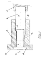
- the shaping device consists of the outer die 1, which has any paragraph 2 and the inner die 3, which consists only of a rotating cylindrical body.
- the can body 4 is clamped in the holder 5 and has an unreduced part 6, which corresponds to a standard can diameter, and a reduced part 7.
- the paragraph between the two parts 5 and 6 lies in a plane of any angle to the axis of rotation 8. Between the two dies 1 and 3 there is only so much space that the wall 10 of the can body 4 can be accommodated.
- the dies 1 and 3 are fixed to one another by means of the flanges 11 and 12 and also serve as fastening in the socket (not shown).
- the design is not limited to the drawing, but is only an example.
Landscapes
- Engineering & Computer Science (AREA)
- Mechanical Engineering (AREA)
- Containers Having Bodies Formed In One Piece (AREA)
- Shaping Metal By Deep-Drawing, Or The Like (AREA)
- Perforating, Stamping-Out Or Severing By Means Other Than Cutting (AREA)
Abstract
Description
Herkömmliche Monoblocdosen besitzen einen nahtlosen zylindrischen Körper, der an seiner Oberseite einen konischen oder kugelförmigen Abschluß aufweist, in dem der Deckel mit Ventil eingesetzt ist.Conventional monobloc cans have a seamless cylindrical body which has a conical or spherical end on its top, in which the lid with valve is inserted.
Die Formgebung ist daher lediglich auf die Höhe, den Durchmesser und die Gestaltung des Abschlusses der Dose beschränkt.The shape is therefore limited to the height, the diameter and the design of the end of the can.
Der Dosenkörper selbst wird durch Fließpressen hergestellt und der Abschluß durch Drücken mittels Gesenken in mehreren Arbeitsgängen ausgeführt. Das erfolgt in der Weise, daß die Gesenke von der offenen Seite des Dosenkörpers über den Mantel geschoben werden und diesen drehsymmetrisch eindrücken. In neuerer Zeit sind auf diese Art auch zylindrische drehsymmetrische Querschnittreduzierungen des Dosenkörpers hergestellt worden. Dadurch konnten Dosenkörper erstellt werden, die die Normsprünge in den Durchmessernormreihen zwischen dem normalen Dosenkörper und dem reduzierten Körperteil aufweisen, wodurch die Verwendung kleiner Deckel und Ventile möglich ist.The can body itself is produced by extrusion and the finish is carried out by pressing in several steps. This is done in such a way that the dies are pushed from the open side of the can body over the jacket and press it in rotationally symmetrically. More recently, cylindrical, rotationally symmetrical cross-sectional reductions of the can body have been produced in this way. This made it possible to create can bodies that have the standard jumps in the diameter standard series between the normal can body and the reduced body part, which means that small lids and valves can be used.
Natürlich ist auch denkbar, den Bereich durch Einführen eines Gesenkes aufzuweiten, doch sind dafür bisher nur Designüberlegungen maßgebend.Of course, it is also conceivable to expand the area by inserting a die, but so far only design considerations have been decisive.
Bei all diesen Verfahren liegt jedoch der Übergang zwischen den beiden Querschnitten in einer Ebene normal zur Drehachse des Dosenkörpers. Eine andere Möglichkeit der Formgebung kann darin bestehen, den Dosenkörper durch Sicken oder Rollen zu reduzieren oder zu erweitern.In all of these methods, however, the transition between the two cross sections lies in a plane normal to the axis of rotation of the can body. Another design option can be to reduce or expand the can body by beads or rollers.
Aus Kostengründen hat sich diese Methode aber nicht durchgesetzt.However, this method has not become established for cost reasons.
Aus Formgebungsgründen ist ein Absatz, bzw. Übergang zwischen dem reduzierten und nicht reduzierten Querschnitt der Dose gewünscht, der beliebig geformt ist. Mit den heute verwendeten Werkzeugen ist das nicht möglich. Denn: durch einen, zur Dosenachse nicht normalen Absatz wird ein ungleicher Druck auf den Dosenkörper ausgeübt und deformiert diesen über einen weiten Bereich, wobei die Wand der Dosen in Falten gezogen wird.For reasons of shape, a step or transition between the reduced and non-reduced cross-section of the can is desired, which is of any shape. This is not possible with the tools used today. Because: due to a heel that is not normal to the can axis, uneven pressure is exerted on the can body and deforms it over a wide area, whereby the wall of the cans is drawn in folds.
Erfindungsgemäß wurde für diesen Zweck ein Werkzeug geschaffen, daß aus einem hohlen Außengesenk, mit drehzylindrischem Innenraum und einem Innengesenk mit drehzylindrischer Außenfläche besteht, das Innengesenk im Außengesenk konzentrisch angeordnet ist und eines der beiden Gesenke einen Absatz beliebiger Form an seiner drehzylindrischen Wand als Übergang zwischen zwei Drehzylindern mit gleicher Achse aufweist.According to the invention, a tool was created for this purpose that consists of a hollow outer die, with a cylindrical interior and an inner die with a cylindrical outer surface, the inner die is arranged concentrically in the outer die and one of the two dies has a paragraph of any shape on its cylindrical wall as a transition between two Has rotary cylinders with the same axis.
Durch die Verwendung des Innengesenkes wird die ungleiche Belastung des Dosenkörpers durch das Außengesenk verhindert, da das Innengesenk die Belastung aufnimmt. Dadurch bleibt der Dosenkörper gerade und eine Verformung erfolgt nur im Bereich des Eindrückens des Absatzes im Gesenk.By using the inner die, the uneven loading of the can body by the outer die is prevented, since the inner die absorbs the load. As a result, the can body remains straight and deformation occurs only in the area of the indentation of the heel in the die.
Falls der Flaschenkörper sich zu seiner offenen Seite hin verjüngt, ist es besonders günstig, das Formgebungsgerät so auszuführen, daß das Außengesenk einen beliebig geformten Absatz aufweist.If the bottle body tapers towards its open side, it is particularly favorable to design the shaping device in such a way that the outer die has an arbitrarily shaped shoulder.
Ein besonders günstiges Verfahren zur Herstellung eines Dosenkörpers für eine Dose mit reduziertem Oberteil und beliebig geformten Absatz aufweist.A particularly inexpensive method for producing a can body for a can with a reduced upper part and arbitrarily shaped paragraph.
Ein besonders günstiges Verfahren zur Herstellung eines Dosenkörpers für eine Dose mit reduziertem Oberteil und beliebig geformten Absatz zwischen den beiden Teilen kann so erfolgen, daß zuerst die Dose in an sich bekannter Weise von ihrer offenen Seite her im Querschnitt reduziert wird und danach die Dose mit der offenen Seite voran in das Formgebungsgerät zwischen die beiden Gesenke bewegt wird, der Absatz am Außengesenk dabei in Richtung zum nichtreduzierten Bereich der Dose weist, die Drehzylinderdurchmesser des Außengesenks etwa dem reduzierten bzw. dem normalen Dosenaußendurchmesser, der Drehzylinderdurchmesser des Innengesenks etwa dem reduzierten Doseninnendurchmesser entspricht und dieser Bereich durch den, sich über ihn drückenden Absatz und Zylinderfläche an der Außenwand des Innengesenks zu liegen kommt, wobei die Dosenwand durch die beiden Gesenke beidseitig der Umformstelle geführt ist.A particularly favorable method for producing a can body for a can with a reduced upper part and any shaped paragraph between the two parts can be done so that the can is first reduced in cross-section from its open side in a known manner and then the can with the is moved open side into the forming device between the two dies, the shoulder on the outer die points towards the unreduced area of the can, the rotary cylinder diameter of the outer die approximately corresponds to the reduced or normal outer diameter of the can, the rotary cylinder diameter of the inner die corresponds approximately to the reduced inner diameter of the can and this area comes to rest on the outer wall of the inner die due to the heel and cylinder surface pressing over it, the can wall being guided through the two dies on both sides of the forming point.
Bei diesem Verfahren wird der reduzierte Teil des Dosenkörpers zwischen den Gesenken geführt und das Wandmaterial kann während des Drückvorganges zwischen die beiden Gesenke fließen und erhält dabei die Gestalt, wie der bereits vorher reduzierte Teil. Ein Ausweichen der Dosenkörperwand ist somit vermieden.In this method, the reduced part of the can body is guided between the dies and the wall material can flow between the two dies during the pressing process and thereby receives the shape like the previously reduced part. Avoiding the can body wall is avoided.
Die drehsymmetrische Verjüngung der Dosen hat sich deshalb als vorbereitender Schritt für diese neue Formgebungsmethode als vorteilhaft erwiesen, da dadurch lediglich der beliebige Absatz auf dem Dosenkörper mit einem Arbeitsschritt hergestellt zu werden braucht und der bereits reduzierte Teil als zusätzliche Stütze des Dosenkörpers zur bekannten Halterung am Dosenboden dient.The rotationally symmetrical tapering of the cans has therefore proven to be advantageous as a preparatory step for this new shaping method, since all that is required is to produce any paragraph on the can body in one work step and the already reduced part as additional support for the can body to the known holder on the can base serves.
Um den Absatz noch weiter in einer regelmäßigen, über den Umfang des Dosenkörpers wiederkehrenden Form zu gestalten ist es auch möglich, daß nach Abschluß des Formgebungsvorganges wenigstens einmal die Dose zurückgezogen, axial verdreht, neuerlich vorbewegt und der nichtreduzierte Dosenteil jeweils weiter verformt wird.In order to shape the sales even more in a regular form that recurs over the circumference of the can body it is also possible that after the shaping process has been completed, the can is withdrawn at least once, axially rotated, moved forward again and the non-reduced can part is further deformed in each case.
So kann man mit einem Außengesenk verschiedene Absätze am Dosenkörper herstellen.So you can create different heels on the can body with an external die.
Nach Formgebung des Absatzes kann man den Dosenkörper im reduzierten, näher zur Dosenöffnung befindlichen Teil in an sich bekannter Weise wieder aufweiten und einen Abschluß aufdrücken.After shaping the heel, the can body can be widened again in the reduced part closer to the can opening in a manner known per se and a closure pressed on.
Die Erfindung wird anhand der nachstehenden Zeichnung beschrieben.The invention is described with reference to the drawing below.
Es zeigen:
- Fig. 1 ein Formgebungsgerät mit einem Dosenkörper im Verformungsvorgang.
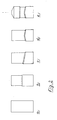
- Fig. 2 die Form einer möglichen Dose nach den jeweiligen Verfahrensschritten bei der Herstellung.
- Fig. 2a den Dosenkörper nach dem Fließpressen.
- Fig. 2b den Dosenkörper, nachdem er in bekannter Weise mit reduziertem Oberteil versehen wurde.
- Fig. 2c den Dosenkörper nach dem Aufpressen eines beliebigen Absatzes.
- Fig. 2d den Dosenkörper nach Beendigung der Formgebung mit einer Erweiterung im reduzierten Teil der Ausformung eines Abschlusses.
- Fig. 1 shows a shaping device with a can body in the molding process.
- Fig. 2 shows the shape of a possible can after the respective process steps in the manufacture.
- 2a the can body after the extrusion.
- Fig. 2b the can body after it has been provided in a known manner with a reduced top.
- Fig. 2c the can body after pressing any paragraph.
- 2d the can body after completion of the shaping with an expansion in the reduced part of the formation of a termination.
Das Formgebungsgerät besteht aus dem Außengesenk 1, das einen beliebigen Absatz 2 aufweist und dem Innengesenk 3, das lediglich aus einem drehzylindrischen Körper besteht. Der Dosenkörper 4 ist in der Halterung 5 eingespannt und weist einen unreduzierten Teil 6, der einem Dosennormdurchmesser entspricht und einem reduzierten Teil 7 auf. Der Absatz zwischen den beiden Teilen 5 und 6 liegt in einer Ebene beliebigen Winkels zur Drehachse 8. Zwischen den beiden Gesenken 1 und 3 ist lediglich soviel Raum, daß die Wand 10 des Dosenkörpers 4 Platz findet.The shaping device consists of the
Die Gesenke 1 und 3 sind mittels der Flansche 11 und 12 zueinander fixiert und dienen diese auch als Befestigung in der nicht dargestellten Dose.The
Die Ausführung ist nicht auf die Zeichnung beschränkt, sondern ist diese nur ein Beispiel.The design is not limited to the drawing, but is only an example.
Claims (5)
Applications Claiming Priority (2)
| Application Number | Priority Date | Filing Date | Title |
|---|---|---|---|
| AT1694/88 | 1988-06-29 | ||
| AT169488A AT390745B (en) | 1988-06-29 | 1988-06-29 | MOLDING DEVICE FOR HOLLOW BODIES |
Publications (2)
| Publication Number | Publication Date |
|---|---|
| EP0349521A2 true EP0349521A2 (en) | 1990-01-03 |
| EP0349521A3 EP0349521A3 (en) | 1991-05-08 |
Family
ID=3518974
Family Applications (1)
| Application Number | Title | Priority Date | Filing Date |
|---|---|---|---|
| EP19890890123 Withdrawn EP0349521A3 (en) | 1988-06-29 | 1989-04-27 | Forming apparatus for hollow articles |
Country Status (2)
| Country | Link |
|---|---|
| EP (1) | EP0349521A3 (en) |
| AT (1) | AT390745B (en) |
Cited By (2)
| Publication number | Priority date | Publication date | Assignee | Title |
|---|---|---|---|---|
| WO2009132269A2 (en) * | 2008-04-24 | 2009-10-29 | Crown Packaging Technology, Inc. | High speed necking configuration |
| US9290329B2 (en) | 2008-04-24 | 2016-03-22 | Crown Packaging Technology, Inc. | Adjustable transfer assembly for container manufacturing process |
Citations (4)
| Publication number | Priority date | Publication date | Assignee | Title |
|---|---|---|---|---|
| DE168713C (en) * | 1902-09-20 | |||
| GB999309A (en) * | 1962-02-14 | 1965-07-21 | Rudolf Lechner | Method of and apparatus for producing seamless metal bottles |
| US3948073A (en) * | 1974-09-27 | 1976-04-06 | Robert Lovell | Apparatus and method of metal forming |
| EP0020926A1 (en) * | 1979-06-25 | 1981-01-07 | Ball Corporation | Method for necking thin wall metallic containers and drawn container produced by this method |
Family Cites Families (4)
| Publication number | Priority date | Publication date | Assignee | Title |
|---|---|---|---|---|
| BE795263A (en) * | 1972-02-11 | 1973-05-29 | K M Engineering A G | MANUFACTURING PROCESS WITHOUT REMOVAL OF CHIPS FROM STEEL SHEET CONTAINERS |
| US4392764A (en) * | 1981-09-18 | 1983-07-12 | Continental Can Company, Inc. | Necked-in container body and apparatus for and method of forming same |
| US4413497A (en) * | 1981-09-21 | 1983-11-08 | Continental Can Company, Inc. | Method of forming domed end for container |
| US4519232A (en) * | 1982-12-27 | 1985-05-28 | National Can Corporation | Method and apparatus for necking containers |
-
1988
- 1988-06-29 AT AT169488A patent/AT390745B/en not_active IP Right Cessation
-
1989
- 1989-04-27 EP EP19890890123 patent/EP0349521A3/en not_active Withdrawn
Patent Citations (4)
| Publication number | Priority date | Publication date | Assignee | Title |
|---|---|---|---|---|
| DE168713C (en) * | 1902-09-20 | |||
| GB999309A (en) * | 1962-02-14 | 1965-07-21 | Rudolf Lechner | Method of and apparatus for producing seamless metal bottles |
| US3948073A (en) * | 1974-09-27 | 1976-04-06 | Robert Lovell | Apparatus and method of metal forming |
| EP0020926A1 (en) * | 1979-06-25 | 1981-01-07 | Ball Corporation | Method for necking thin wall metallic containers and drawn container produced by this method |
Cited By (7)
| Publication number | Priority date | Publication date | Assignee | Title |
|---|---|---|---|---|
| WO2009132269A2 (en) * | 2008-04-24 | 2009-10-29 | Crown Packaging Technology, Inc. | High speed necking configuration |
| WO2009132269A3 (en) * | 2008-04-24 | 2009-12-30 | Crown Packaging Technology, Inc. | High speed necking configuration |
| US8601843B2 (en) | 2008-04-24 | 2013-12-10 | Crown Packaging Technology, Inc. | High speed necking configuration |
| US9290329B2 (en) | 2008-04-24 | 2016-03-22 | Crown Packaging Technology, Inc. | Adjustable transfer assembly for container manufacturing process |
| US9308570B2 (en) | 2008-04-24 | 2016-04-12 | Crown Packaging Technology, Inc. | High speed necking configuration |
| US9968982B2 (en) | 2008-04-24 | 2018-05-15 | Crown Packaging Technology, Inc. | High speed necking configuration |
| US10751784B2 (en) | 2008-04-24 | 2020-08-25 | Crown Packaging Technology, Inc. | High speed necking configuration |
Also Published As
| Publication number | Publication date |
|---|---|
| AT390745B (en) | 1990-06-25 |
| ATA169488A (en) | 1989-12-15 |
| EP0349521A3 (en) | 1991-05-08 |
Similar Documents
| Publication | Publication Date | Title |
|---|---|---|
| DE10040173B4 (en) | Method for expanding and deforming a can body and apparatus for carrying out the method | |
| DE69314141T2 (en) | Manufacture of diffusion welded joints on superplastic metal structures | |
| DE2624854C3 (en) | Roller pressing device for producing a cup-shaped pulley blank | |
| EP3253567A1 (en) | Powder press having a cone-shaped substructure | |
| DE69604521T2 (en) | Production of a metal container in a mold | |
| DE3321285C2 (en) | Method for producing a profile from dry powder material and device for this | |
| WO2002081118A1 (en) | Method for producing a rolled edge | |
| DE69200315T3 (en) | Device and method for reshaping containers. | |
| DE69500280T2 (en) | Method and device for producing an edge, in particular on a lamp reflector | |
| DE19639677A1 (en) | Manufacture of outer element of universal joint with cross slots | |
| EP0349521A2 (en) | Forming apparatus for hollow articles | |
| DE2624872A1 (en) | METHOD OF MANUFACTURING UNDIVIDED WHEELS | |
| DE2649822B2 (en) | Method and device for introducing a toroidally preformed green tire into a vulcanizing mold | |
| EP0255719B1 (en) | Device and method for manufacturing conically or cylindrically shaped hollow bodies with a part projecting outward, in particular cups with a handle | |
| EP1165272B1 (en) | Method of producing homokinetic joints | |
| DE19945743A1 (en) | Method and device for connecting overlapping plate-shaped components | |
| DE1777109A1 (en) | Method and device for manufacturing wheel rims | |
| DE2953354C2 (en) | Method for producing an inner joint body for a constant velocity joint | |
| DE1627681C3 (en) | Methods and tools for making a rim | |
| DE816780C (en) | Method and tool for pressing engine pistons | |
| EP0690774A1 (en) | Isostatic press tool for the production of steep-walled pot-shaped articles from granular ceramic material | |
| EP0812636A1 (en) | Method and device for producing rotationally symmetrical workpieces, in particular vehicle wheels | |
| DE2719948A1 (en) | Compressed air reservoir for motor vehicle - has two extruded aluminium alloy pots welded together whilst centred on mandrels | |
| EP0670207A1 (en) | Device for making cylindrical tubular products | |
| DE3513960C2 (en) |
Legal Events
| Date | Code | Title | Description |
|---|---|---|---|
| PUAI | Public reference made under article 153(3) epc to a published international application that has entered the european phase |
Free format text: ORIGINAL CODE: 0009012 |
|
| 17P | Request for examination filed |
Effective date: 19890510 |
|
| AK | Designated contracting states |
Kind code of ref document: A2 Designated state(s): BE CH DE ES FR GB GR IT LI LU NL SE |
|
| PUAL | Search report despatched |
Free format text: ORIGINAL CODE: 0009013 |
|
| AK | Designated contracting states |
Kind code of ref document: A3 Designated state(s): BE CH DE ES FR GB GR IT LI LU NL SE |
|
| STAA | Information on the status of an ep patent application or granted ep patent |
Free format text: STATUS: THE APPLICATION IS DEEMED TO BE WITHDRAWN |
|
| 18D | Application deemed to be withdrawn |
Effective date: 19911031 |