EP0349352A2 - Appareil automatique pour appliquer la cire sur les skis - Google Patents
Appareil automatique pour appliquer la cire sur les skis Download PDFInfo
- Publication number
- EP0349352A2 EP0349352A2 EP89400694A EP89400694A EP0349352A2 EP 0349352 A2 EP0349352 A2 EP 0349352A2 EP 89400694 A EP89400694 A EP 89400694A EP 89400694 A EP89400694 A EP 89400694A EP 0349352 A2 EP0349352 A2 EP 0349352A2
- Authority
- EP
- European Patent Office
- Prior art keywords
- wax
- ski
- strips
- coating apparatus
- brushing
- Prior art date
- Legal status (The legal status is an assumption and is not a legal conclusion. Google has not performed a legal analysis and makes no representation as to the accuracy of the status listed.)
- Withdrawn
Links
Images


Classifications
-
- A—HUMAN NECESSITIES
- A63—SPORTS; GAMES; AMUSEMENTS
- A63C—SKATES; SKIS; ROLLER SKATES; DESIGN OR LAYOUT OF COURTS, RINKS OR THE LIKE
- A63C11/00—Accessories for skiing or snowboarding
- A63C11/04—Accessories for skiing or snowboarding for treating skis or snowboards
- A63C11/08—Apparatus for waxing or dewaxing
Definitions
- the present invention relates to an automatic wax coating apparatus for use with skis and, more particularly, to an apparatus for automatically coating the sliding surfaces of ski strips with a liquid wax.
- Ski contestants have heretofore manually applied a wax coating to the sliding surfaces of their skis in a series of steps performed in the following order.
- skiers tend to complete the application of a wax coat in a time period which is short compared with the time when it would normally take for ski contestants to complete the application of a wax coat. For this reason, many skiers omit the above procedures 2) and 5).
- ski contestants or skiers apply a wax coat
- an object of the present invention is to provide a compact apparatus of the type in which the manual operations which attend the application of a wax coat are automated.
- an automatic wax coating apparatus for use with skis characterized in that a securing device for securing ski strips, a wax supplying device, a brushing device and a movement device are provided in the interior of a box for accommodating the ski strips, in which the brushing device comprises a hot air nozzle for blowing hot air onto the ski strips, a roller brush for brushing the sliding surfaces of the ski strips, and a wax nozzle for spraying the sliding surfaces of the ski strips with a wax supplied from the wax supplying device, whereby the brushing device can be moved along the longitudinal axes of the ski strips by means of the movement device.
- ski strips are located in the interior of the box-like body so that they can be clamped and secured by the securing device.
- the securing device clamps and secures the ski strips so that the brushing device may be moved along the longitudinal axes of the ski strips which has thus been located in the box-like body.
- the brushing device While the brushing device is moving along the sliding surfaces of the ski strips, the brushing device blows hot air through the hot air nozzle, implementing brushing using the roller brush, and spraying from the wax nozzle the wax supplied from the wax supplying device.
- the brushing device makes a plurality of reciprocating movements along the longitudinal axes of the ski strips to apply a wax coat of even more accurately controlled uniformity, thickness, surface texture and so forth.
- wax coating which has heretofore required manual operation is automated by providing the automatic wax coating apparatus for use with skis, and the following advantages can be provided.
- the required manual operation consists merely of placing ski strips into and removing them from the wax coating apparatus according to the present embodiment. Accordingly, the number of manual operations can be greatly reduced and, additionally, a wax coating of accurately controlled uniformity, thickness, and surface texture can be applied by automation.
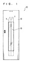
- An automatic wax coating apparatus 10 for use with skis (hereinafter referred to as the"wax coating apparatus 10") is constituted by a box-like body 11 in the form of a rectangular parallelepiped in which two ski strips 1 can be disposed vertically and side-by-side.
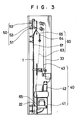
- the body 11 includes a securing device 20 for clamping and securing the ski strips 1 that are thus vertically accommodated, a wax supplying device 30 for both storing a wax and supplying it, a compressed-air supplying device 40 for generating compressed air and supplying it, a brushing device 50 for effecting spraying of a wax, brushing and so forth, and a movement device 60 for causing the brushing device 50 to move along the longitudinal axes of the ski strips 1.
- the body 11 has a swingable door 12 serving as a front plate which can be freely opened and closed, and a transparent front glass window 13 is mounted near the center of the swingable door 12 so as to allow observation of the interior of the body 11.
- a door lock 70 is provided on a portion of the interior of the body 11 of the wax coating apparatus 10 according to the present embodiment (refer to Fig. 4).
- the door lock 70 serves to prevent the swingable door 12 from opening during operation of the wax coating apparatus 10, thereby preventing a wax being ejected from the wax coating apparatus 10.
- the door lock 70 is constituted by a door-lock air cylinder 71, a door-lock checking sensor 72 and a door-lock solenoid valve 73.
- the door-lock air cylinder 71 serves to lock or unlock the swingable door 12 by means of the compressed air supplied from the compressed-air supplying device 40.
- the door-lock checking sensor 72 is a sensor which serves to detect whether or not the swingable door 12 is locked. If the swingable door 12 is not correctly locked, the door-lock checking sensor issues a command to restrain the brushing device 50 from operating.
- the door-lock solenoid valve 73 is a solenoid valve which provides ON-OFF control to determine whether or not compressed air required as power should be supplied when the door-lock air cylinder 71 is to lock or unlock the swingable door 12.
- a coin slot is provided in the outer surface of the swingable door 12.
- the securing device 20 serves to secure two ski strips 1 which are vertically disposed in the inner space of the body 11 with their respective sliding surfaces arranged in the same plane so as to enable the brushing device 50 to perform its function correctly.
- the securing device 20 is constituted by a clamper 21, a clamping checking sensor 24 (Fig. 4) and a clamper solenoid valve 23 (Fig. 4).
- a strip holder 22 is provided on the bottom of the interior of the body 11 for securing the lower ends of the respective ski strips 1 when the ski strips 1 are secured by the securing device 20.
- the clamper 21 serves to clamp and secure the two ski strips 1 by using, as power, the compressed air supplied from the compressed-air supplying device 40.
- the clamper 21 is disposed near the center of the inner space of the body 11.
- the clamper checking sensor 24 is a sensor for detecting whether the two ski strips 1 are secured in a correctly clamped state by the clamper 21. If they are not correctly secured, the clamper checking sensor 24 issues a command to restrain the brushing device 50 from operating.
- the clamper solenoid valve 23 is a solenoid valve which provides ON-OFF control to determine whether or not the compressed air required as power should be supplied when the clamper 21 is to clamp or unclamp the two ski strips 1.
- the wax supplying device 30 is a device which serves to store the wax and to feed the stored wax to a wax spraying nozzle 53.
- the wax supplying device 30 is constituted by a wax tank 31 for storing the wax, a wax pump 32 for feeding the wax stored in the wax tank 31, a wax tube 33 through which the wax fed by the wax pump 32 is supplied to the brushing device 50, a flow control valve 34 (Fig. 4) for regulating the flow of the wax fed from the wax pump 32 to the brushing device 50, and a three-way solenoid valve 35 (Fig. 4) for mixing the wax passed through the flow control valve 34 (Fig. 4) and the compressed air from the compressor 42 and supplying the mixture to the brushing device 50.
- the wax supplying device 30 is located on the left-hand side in the space of the interior of the body 11 for accommodating ski strips 1, as viewed from the same side as the swingable door 12.
- the wax pump 32 and the wax tank 31, the flow control valve 34, the three-way solenoid valve 35, and the wax tube 33 are located on that order from the bottom of the interior of the body 11.
- the wax tube 33 is made from a spiral tube.
- a level sensor is provided in the interior of the wax tank 31. If the amount of wax remaining becomes small, the level sensor serves to issue an alarm, restrain the brushing device 50 from operating, and so forth.
- the compressed-air supplying device 40 is a device which serves to generate compressed air and supply the compressed air.
- the compressed-air supplying device 40 is constituted by a blower 41 for supplying air, a compressor 42 for generating compressed air from the air supplied from the blower 41, a filter 44 (Fig. 4) for eliminating dirt, dust and so forth contained in the compressed air generated by the compressor 42, a regulator 45 (Fig. 4) for regulating the pressure of the compressed air passed through the filter 44 (Fig. 4), a compressed-air tube 43 through which the compressed air whose pressure has been regulated by the regulator 45 (Fig. 4) is fed to the brushing device 50, and a flow control valve 46 (Fig. 4) for regulating the flow of the compressed air.
- the compressed-air supplying device 40 is located on the right-hand side in the space of the interior of the body 11 for accommodating ski strips, as viewed from the same side as the swingable door 12.
- the blower 41, the compressor 42, the flow control valve 46 and the compressed-air tube 43 are located on that order from the bottom of the interior of the body 11.
- the brushing device 50 which is supplied with compressed air through the compressed-air tube 43 is caused to move up and down in the interior of the body 11 by the movement device 60, the distance between the compressor 42 and the brushing device 50 is not constant. Accordingly, the compressed-air tube 43 is made from a spiral tube.
- the brushing device 50 is a device which effects application of a wax coat and so forth while moving along the longitudinal axes of ski strips 1 by the driving of the movement device 60.
- the brushing device 50 is provided with a heater 54 (Fig. 4) for heating the compressed air supplied from the compressed-air supplying device 40 and converting it into hot air, a hot air nozzle 51 for blowing the hot air produced by the heater 54 (Fig.
- a roller brush 52 for removing dust from the sliding surfaces of the ski strips 1 in preparation for coating of a new wax or polishing the newly coated wax, the roller brash 52 being arranged to effect brushing the ski strips 1 along their longitudinal axes, and a wax spraying nozzle 53 for spraying the wax supplied from the wax tank 31 on to the sliding surfaces of the ski strips 1.
- the brushing device 50 is constituted by an integral combination of the hot air nozzle 51, the roller brash 52 and the wax spraying nozzle 53 which are arranged in that order from the lower side.
- the brushing device 50 is located near the upper ends of the ski strips 1 which are accommodated in the body 11.
- the movement device 60 serves to cause the brushing device 50 to move along the longitudinal axes of the ski strips 1.
- the movement device 60 is constituted by a rail 61 serving to guide the movement of the brushing device 50, a reversible motor 62 serving as the power source required for the brushing device 50 to move back and forth along the rail 61, a wire 63 serving as a medium for transmitting the power of the reversible motor 62 to the brushing device 50, a tension pulley 64 for applying tension to the wire 63, and a direction checking sensor 65 serving to determine the turning point of the direction of rotation of the reversible motor 62.
- the rail 61 is vertically disposed along the longitudinal axes of the ski strips 1.
- the reversible motor 62 is disposed at the bottom of the body 11 on the lower left as viewed from the same side as the swingable door 12.
- the reversible motor 62 makes forward rotation and reverse rotation as well as pause in accordance with a command from either of the direction checking sensors 65.
- the direction checking sensors 65 are disposed at two locations near the upper end and lower end of the rail 61.
- Fig. 4 shows that the wax coating apparatus 10 according to the present embodiment is constituted by two lines: one line (hereinafter referred to as the "first line”) is arranged to operate by utilizing, as power, the compressed air supplied by the compressor 42 and another line (hereinafter referred to as the "second line”) is arranged in association with the wax supplied from the wax tank 31.
- first line one line
- second line another line
- the first line is constituted by the securing device 20, the door lock 70, a part of the brushing device 50 constituted by the heater 54 and the hot air nozzle 51, and the compressed-air supplying device 40 for supplying compressed air serving to operate these devices.
- the second line is constituted by the wax supplying device 30, the three-way solenoid valve 35, and the wax spraying nozzle 53 which constitutes a part of the brushing device 50.
- a skier opens the swingable door 12, supports the lower ends (trailing ends) of his two ski strips 1 on the strip holder 22, and locates the approximately mid portions of the respective ski strips 1 on the clamper 21.
- the door-lock cylinder 71 (Fig. 4) locks the swingable door 12 by means of the compressed air supplied from the compressed-air supplying device 40.
- the door-lock checking sensor 72 (Fig. 3) detects the fact that the swingable door 12 is not perfectly locked, the door-lock checking sensor 72 issues a command to restrain the brushing device 50 from operating.
- the clamper 21 clamps and secures the two ski strips 1 by means of the compressed air supplied from the compressed-air supplying device 40.
- the clamper checking sensor 24 (Fig. 4) detects the fact that the ski strips 1 are not correctly clamped or secured, the clamper checking sensor 24 issues a command to restrain the brushing device 50 from operating.
- the reversible motor 62 initiates its forward running and thus the brushing device 50 is caused to move along the sliding surfaces of the ski strips 1 from the upper to lower ends thereof by the rotational torque of the reversible motor 62.
- the brushing device 50 operates as folows:
- the brushing device 50 After having reached the lower ends of the ski strips 1, the brushing device 50 is caused to move along the sliding surfaces of the ski strips 1 from the lower to upper ends thereof by the reverse rotational torque of the reversible motor 62. During this movement, the brushing device 50 operates as follows:
- the brushing device 50 completes applying a wax coat.
- the compressed air supplied from the compressed-air supplying device 40 to the clamper 21 is controlled by the clamper solenoid valve 23 (Fig. 4), and thus the clamping of the ski strips 1 by the clamper 21 is released.
- the compressed air supplied from the compressed-air supplying device 40 to the door-lock air cylinder 71 (Fig. 4) is controlled by the door-lock solenoid valve 73 (Fig. 4), and thus the locking of the swingable door 21 by the door-lock air cylinder 71 (Fig. 4) is released.
- wax coating which has heretofore been manually carried out is automated by providing the automatic wax coating apparatus 10 for use with skis. Accordingly, the following advantages are provided.
- the required manual operation consists merely of placing the ski strips 1 into and removing them from the wax coating apparatus according to the present embodiment. Accordingly, the number of manual operations is greatly reduced and, additionally, a wax coat of accurately controlled uniformity, thickness, and surface texture can be applied by automation.
- the brushing device 50 is constructed as a device constituted by an integral combination of the following three functions: the hot air nozzle 51 for blowing hot air to melt the snow stuck to the sliding surfaces of the ski strips 1 or to dry the wax coated, the roller brush 52 for removing dust stuck to the sliding surfaces of the ski strips 1 and for polishing the wax coated so as to impart the desired surface texture to it, and the wax spraying nozzle 53 for spraying the wax. Accordingly, the efficiency of applying and drying the wax is improved. In particular, the step of melting and drying the snow stuck to the ski strips 1 and the step of drying the wax coated by hot air can be efficiently effected, thereby enabling a reduction in the required working time.
- the clamp sensor 24 and the lock sensor 72 are provided for detecting whether or not the ski strips 1 are correctly secured and whether the swingable door 12 is correctly locked, respectively, and the wax coating apparatus 10 does not operate if the securing of the ski strips 1 or the locking of the swingable door 12 is not correct. Accordingly, it is possible to provide a wax coating apparatus which is characterized by safe and sure operations in that, for example, the ejection of a wax from the wax coating apparatus 10 can be prevented.
- the wax coating apparatus 10 provided in the present embodiment further has the advantage that, since the wax coating apparatus 10 is provided with the front glass window 13, a skier can observe with ease the manner in which the brushing device 50 is applying a wax coat.
- the front glass window 13 is provided in the swingable door 12.
- the front glass window 13 may be omitted for the purpose of a reduction in cost.
- the securing device 20 or the door lock 70 in the present embodiment is not limited only to those shown in the above-described embodiment. For example, it may be constructed to operate manually for the purpose of a reduction in cost.
- the clamper 21 clamps and secures ski strips 1.
- the clamper 21 may be arranged to clamp and secure ski strips 1, for example, before the swingable door 12 has been closed. If the clamper 21 is arranged to operate in that order, even if the clamping and securing of ski strips 1 by the clamper 21 is not correct, it is possible to immediately modify the operation of the clamper 21.
- the brushing device 50 is arranged to make one reciprocating motion along the rail 61 and the application of a wax coat by the spray nozzle 53 is completed in one step when the brushing device 50 is moving from the upper to the lower ends of the rail 61.
- the number of coating steps is not limited only to one.
- the application of a wax coat by the wax spraying nozzle 53 may be implemented further when the brushing device 50 is moving from the upper to lower ends of the rail 61.
- the brushing device 50 may also be arranged to reciprocate along the rail 61 by a plurality of times for the purpose of applying a wax coat.
- the swingable door 12 is closed and a predetermined coin is thrown into the coin slot (not shown) and thus the sequence of operations of the wax coating apparatus 10 is initiated.
- the arrangement of the present embodiment is not limited only to the above-described one.
- the swingable door 12 may be arranged to be locked when in no use and to be unlocked when a predetermined coin is thrown into the coin slot (not shown).
- a coin slot may be omitted, that is, the apparatus may be arranged so that it can be operated free of charge.
Landscapes
- Vehicle Cleaning, Maintenance, Repair, Refitting, And Outriggers (AREA)
- Spray Control Apparatus (AREA)
- Coating Apparatus (AREA)
Applications Claiming Priority (2)
| Application Number | Priority Date | Filing Date | Title |
|---|---|---|---|
| JP63163481A JP2678290B2 (ja) | 1988-06-30 | 1988-06-30 | スキー用自動ワックスがけ機 |
| JP163481/88 | 1988-06-30 |
Publications (2)
| Publication Number | Publication Date |
|---|---|
| EP0349352A2 true EP0349352A2 (fr) | 1990-01-03 |
| EP0349352A3 EP0349352A3 (fr) | 1991-02-06 |
Family
ID=15774695
Family Applications (1)
| Application Number | Title | Priority Date | Filing Date |
|---|---|---|---|
| EP19890400694 Withdrawn EP0349352A3 (fr) | 1988-06-30 | 1989-03-14 | Appareil automatique pour appliquer la cire sur les skis |
Country Status (4)
| Country | Link |
|---|---|
| US (1) | US4899692A (fr) |
| EP (1) | EP0349352A3 (fr) |
| JP (1) | JP2678290B2 (fr) |
| CA (1) | CA1312726C (fr) |
Cited By (5)
| Publication number | Priority date | Publication date | Assignee | Title |
|---|---|---|---|---|
| FR2686800A1 (fr) * | 1992-02-04 | 1993-08-06 | Skid Sa | Dispositif pour l'application d'un fart pateux sur une semelle de ski. |
| WO1998018530A1 (fr) * | 1996-10-29 | 1998-05-07 | Human Corporation | Machine a farter, technique de commande, generateur de chaleur a utiliser avec cette machine a farter et logement |
| WO2009059037A2 (fr) * | 2007-10-31 | 2009-05-07 | Briareos, Inc. | Skis et analogues fartés à l'aide d'une composition de cire contenant du polytétrafluoroéthylène (ptfe) pratiquement superhydrophobe, et composition, procédé et kit pour sa production |
| WO2016161365A1 (fr) | 2015-04-01 | 2016-10-06 | Skiquiky, Llc | Dispositif et procédé de fartage d'équipements de sport de neige |
| US10589165B2 (en) | 2015-04-01 | 2020-03-17 | Skiquicky, Inc. | Snow sport equipment waxing device and method |
Citations (3)
| Publication number | Priority date | Publication date | Assignee | Title |
|---|---|---|---|---|
| DE8533909U1 (de) * | 1985-12-03 | 1986-06-12 | Jäger, Peter, 8990 Lindau | Vorrichtung zum Auftragen von Wachs auf Skier |
| EP0195729A1 (fr) * | 1985-02-28 | 1986-09-24 | Skid | Procédé et dispositif pour le fartage de skis par pulvérisation |
| DE8701613U1 (fr) * | 1986-11-20 | 1987-03-26 | Mittermeier, Josef, 8261 Pleiskirchen, De |
Family Cites Families (5)
| Publication number | Priority date | Publication date | Assignee | Title |
|---|---|---|---|---|
| US2537511A (en) * | 1948-05-22 | 1951-01-09 | Coulombe Maurice | Ski waxing machine |
| CH425577A (fr) * | 1964-10-12 | 1966-11-30 | Rey Henri | Dispositif pour farter des skis |
| DE3227922A1 (de) * | 1982-07-27 | 1984-02-02 | Peter Mario 8960 Kempten Amann | Behandlungsvorrichtung fuer skier |
| US4577586A (en) * | 1985-05-02 | 1986-03-25 | Morris Fredric H | Automatic ski waxing machine |
| DE8608052U1 (de) * | 1986-03-22 | 1986-04-30 | kabelmetal electro GmbH, 3000 Hannover | Vorrichtung zum Auftragen einer wachsartigen Masse auf die Lauffläche von Skiern |
-
1988
- 1988-06-30 JP JP63163481A patent/JP2678290B2/ja not_active Expired - Lifetime
-
1989
- 1989-03-13 CA CA000593514A patent/CA1312726C/fr not_active Expired - Fee Related
- 1989-03-14 US US07/322,855 patent/US4899692A/en not_active Expired - Fee Related
- 1989-03-14 EP EP19890400694 patent/EP0349352A3/fr not_active Withdrawn
Patent Citations (3)
| Publication number | Priority date | Publication date | Assignee | Title |
|---|---|---|---|---|
| EP0195729A1 (fr) * | 1985-02-28 | 1986-09-24 | Skid | Procédé et dispositif pour le fartage de skis par pulvérisation |
| DE8533909U1 (de) * | 1985-12-03 | 1986-06-12 | Jäger, Peter, 8990 Lindau | Vorrichtung zum Auftragen von Wachs auf Skier |
| DE8701613U1 (fr) * | 1986-11-20 | 1987-03-26 | Mittermeier, Josef, 8261 Pleiskirchen, De |
Cited By (7)
| Publication number | Priority date | Publication date | Assignee | Title |
|---|---|---|---|---|
| FR2686800A1 (fr) * | 1992-02-04 | 1993-08-06 | Skid Sa | Dispositif pour l'application d'un fart pateux sur une semelle de ski. |
| EP0555164A1 (fr) * | 1992-02-04 | 1993-08-11 | SKID Société Anonyme | Dispositif pour l'application d'un fart pâteux sur une semelle de ski |
| WO1998018530A1 (fr) * | 1996-10-29 | 1998-05-07 | Human Corporation | Machine a farter, technique de commande, generateur de chaleur a utiliser avec cette machine a farter et logement |
| WO2009059037A2 (fr) * | 2007-10-31 | 2009-05-07 | Briareos, Inc. | Skis et analogues fartés à l'aide d'une composition de cire contenant du polytétrafluoroéthylène (ptfe) pratiquement superhydrophobe, et composition, procédé et kit pour sa production |
| WO2009059037A3 (fr) * | 2007-10-31 | 2009-10-29 | Briareos, Inc. | Skis et analogues fartés à l'aide d'une composition de cire contenant du polytétrafluoroéthylène (ptfe) pratiquement superhydrophobe, et composition, procédé et kit pour sa production |
| WO2016161365A1 (fr) | 2015-04-01 | 2016-10-06 | Skiquiky, Llc | Dispositif et procédé de fartage d'équipements de sport de neige |
| US10589165B2 (en) | 2015-04-01 | 2020-03-17 | Skiquicky, Inc. | Snow sport equipment waxing device and method |
Also Published As
| Publication number | Publication date |
|---|---|
| US4899692A (en) | 1990-02-13 |
| EP0349352A3 (fr) | 1991-02-06 |
| CA1312726C (fr) | 1993-01-19 |
| JPH0213484A (ja) | 1990-01-17 |
| JP2678290B2 (ja) | 1997-11-17 |
Similar Documents
| Publication | Publication Date | Title |
|---|---|---|
| US8122563B2 (en) | Bowling lane conditioning machine | |
| CA2537850C (fr) | Appareil et procede de conditionnement d'une piste de quilles au moyen d'injecteurs de distribution de precision | |
| US4899692A (en) | Automatic wax coating apparatus for use with skis | |
| US5279700A (en) | Automated wallboard taping apparatus and process therefor | |
| US10723498B2 (en) | Vehicle part hole patch applicator arrangement | |
| CZ284192B6 (cs) | Zařízení pro nanášení tekutin | |
| JP5065375B2 (ja) | 動物の収容設備の床を清掃する装置及び方法 | |
| US5407482A (en) | Primer applying and surface wiping apparatus | |
| US5597344A (en) | Machine for treating, in particular sanding ski soles | |
| US5279684A (en) | Wallboard taping process | |
| US5240500A (en) | Gypsum based wallboard taping composition | |
| JPS62202384A (ja) | テ−プ巻き取り装置 | |
| US20140208530A1 (en) | Bowling Lane Machine | |
| WO1989010796A1 (fr) | Procede de changement de couleur et de lavage destine a etre utilise dans un dispositif de vaporisation d'une couche, de preference de peinture, et equipement de realisation dudit procede | |
| WO1998018530A1 (fr) | Machine a farter, technique de commande, generateur de chaleur a utiliser avec cette machine a farter et logement | |
| TW308548B (en) | Automatic waxer for skis | |
| JP2689235B2 (ja) | 自動靴磨装置及びその運転制御方法 | |
| AU2004272003C1 (en) | Apparatus and method for conditioning a bowling lane using precision delivery injectors | |
| DE3833103A1 (de) | Einrichtung zum automatischen wachsen von skiern | |
| CN220246451U (zh) | 一种用于人造仿毛纤维染色处理的风干装置 | |
| EP0420410B1 (fr) | Procédé et dispositif pour fournir un adhésif sur une fibre optique pendant bobinage | |
| GB2232909A (en) | Painting small details on an article and cleaning paint nozzles | |
| JPS6152747B2 (fr) | ||
| KR19980038471U (ko) | 롱지부 도장 장치 | |
| JP2969239B2 (ja) | プリント基板の防湿絶縁塗料塗布装置 |
Legal Events
| Date | Code | Title | Description |
|---|---|---|---|
| PUAI | Public reference made under article 153(3) epc to a published international application that has entered the european phase |
Free format text: ORIGINAL CODE: 0009012 |
|
| AK | Designated contracting states |
Kind code of ref document: A2 Designated state(s): CH DE ES FR GB IT LI |
|
| PUAL | Search report despatched |
Free format text: ORIGINAL CODE: 0009013 |
|
| AK | Designated contracting states |
Kind code of ref document: A3 Designated state(s): CH DE ES FR GB IT LI |
|
| 17P | Request for examination filed |
Effective date: 19910627 |
|
| 17Q | First examination report despatched |
Effective date: 19920804 |
|
| STAA | Information on the status of an ep patent application or granted ep patent |
Free format text: STATUS: THE APPLICATION IS DEEMED TO BE WITHDRAWN |
|
| 18D | Application deemed to be withdrawn |
Effective date: 19930215 |