EP0349325A2 - Gerät zur Uebertragung eines digitalen Signals - Google Patents
Gerät zur Uebertragung eines digitalen Signals Download PDFInfo
- Publication number
- EP0349325A2 EP0349325A2 EP89306628A EP89306628A EP0349325A2 EP 0349325 A2 EP0349325 A2 EP 0349325A2 EP 89306628 A EP89306628 A EP 89306628A EP 89306628 A EP89306628 A EP 89306628A EP 0349325 A2 EP0349325 A2 EP 0349325A2
- Authority
- EP
- European Patent Office
- Prior art keywords
- code
- signal
- data signal
- error
- data
- Prior art date
- Legal status (The legal status is an assumption and is not a legal conclusion. Google has not performed a legal analysis and makes no representation as to the accuracy of the status listed.)
- Withdrawn
Links
Images


Classifications
-
- H—ELECTRICITY
- H03—ELECTRONIC CIRCUITRY
- H03M—CODING; DECODING; CODE CONVERSION IN GENERAL
- H03M13/00—Coding, decoding or code conversion, for error detection or error correction; Coding theory basic assumptions; Coding bounds; Error probability evaluation methods; Channel models; Simulation or testing of codes
-
- G—PHYSICS
- G11—INFORMATION STORAGE
- G11B—INFORMATION STORAGE BASED ON RELATIVE MOVEMENT BETWEEN RECORD CARRIER AND TRANSDUCER
- G11B20/00—Signal processing not specific to the method of recording or reproducing; Circuits therefor
- G11B20/10—Digital recording or reproducing
- G11B20/18—Error detection or correction; Testing, e.g. of drop-outs
- G11B20/1806—Pulse code modulation systems for audio signals
- G11B20/1809—Pulse code modulation systems for audio signals by interleaving
-
- G—PHYSICS
- G11—INFORMATION STORAGE
- G11B—INFORMATION STORAGE BASED ON RELATIVE MOVEMENT BETWEEN RECORD CARRIER AND TRANSDUCER
- G11B20/00—Signal processing not specific to the method of recording or reproducing; Circuits therefor
- G11B20/10—Digital recording or reproducing
- G11B20/12—Formatting, e.g. arrangement of data block or words on the record carriers
- G11B20/1201—Formatting, e.g. arrangement of data block or words on the record carriers on tapes
- G11B20/1207—Formatting, e.g. arrangement of data block or words on the record carriers on tapes with transverse tracks only
- G11B20/1208—Formatting, e.g. arrangement of data block or words on the record carriers on tapes with transverse tracks only for continuous data, e.g. digitised analog information signals, pulse code modulated [PCM] data
Definitions
- This invention relates to digital signal transmission apparatus.
- the invention is particularly, but not exclusively, suitable for use in recording pulse code modulated (PCM) signals onto a magnetic tape using rotary heads, and for error correction in a digital encoder for recording high quality audio PCM data, as disclosed in US patent specification US-A-4 551 771.
- PCM pulse code modulated
- error correction encoding apparatus and method for use with information symbols arranged two-dimensionally in a matrix form in which encoding processes of error detection and error correction codes, for example Reed-Solomon codes are executed in each of the vertical and lateral directions of the information symbols. These codes are transmitted for each column (referred to as a block) in the vertical direction.
- the error correction is performed by using a first error detection and error correction code (referred to as a C1 code or a first error detection code) and, at the same time, a pointer indicative of the presence or absence of errors is formed.
- the errors are corrected by a second error detection and a error correction code (referred to as a C2 code or a second error detection code) in dependence on to this pointer.
- one block of data is formed by the addition of a synchronization signal and a header consisting of auxiliary data such as a block address, a time code, etc.
- a two-dimensional arrangement is formed by a plurality of blocks. Since redundancy increases when block addresses are added to all blocks, for example, 100 blocks, it is desirable that block addresses should be contained in a part of blocks, and auxiliary data, etc, should be inserted into a part of blocks by omitting the block addresses.
- an error correction encoding apparatus in which a whole header together with a data portion is C1 encoded and the encoding of a C2 code is performed for the main data included in the header, excluding addresses, thereby enabling error protection of the part of the main data included in the header to be made strong, so that the main data can be recorded into the header part.
- the insertion of audio data into the header facilitates the adjustment of synchronization between a picture which is reproduced from the tape and an audio sound, by varying the number of audio data words which are included in a frame of data area.
- This error correction encoding apparatus is suitable when it is used in an 8-mm video tape recorder (VTR) as disclosed in US patent specification US-A-4 551 771, in which both a video signal of one field and audio PCM signals of one field, that is, time base compressed audio PCM signals are recorded on a magnetic tape by a single scan.
- VTR video tape recorder
- the sampling frequency of the audio PCM signals is selected to be 2f h (where f h is the horizontal frequency). Therefore, the rotary heads which rotate at a frame frequency and a sampling system are synchronized, and the problem of asynchronization between an image and an audio sound does not occur.
- the sampling frequency of the conventional 8-mm VTR is too low where audio signals of a high quality are to be recorded and reproduced.
- the number of sampling data included in one field period is not an integer. Therefore, when both a video signal and audio PCM signals are recorded on the same track, as in the 8-mm VTR, the problem occurs of asynchronization between the video image and the corresponding audio sound.
- the sampling frequency cannot be divided by a frequency of an encoded unit, for example, the field frequency
- the sample number contained in one frame of a code structure varies over a range of numbers close to the quotient of the division.
- Data processing on the reception side can be performed without any trouble by transmitting an identification signal indicative of the sample number.
- the foregoing PCM processor for an 8-mm VTR is disclosed in US patent application number 262 523.
- a 2-symbol (16 bits) block address is inserted into a header, and a 1-symbol block address is inserted into a block in which a 1-symbol audio PCM signal is contained as auxiliary data.
- a block in which an audio PCM signal is included into a header is prescribed to have a block address of an odd-number whose least significant bit is "1".
- the format in which there are mixed together blocks having block addresses and blocks having data such as an audio PCM signal other than an address but having no block address is desirable. In this case, since no block address is added to the blocks in which data such as an audio PCM signal are inserted, it is impossible to distinguish a header content by the block address.
- embodiments of the present invention perform an identification of a header content by a redundant code of an error detection code which is added for error detection of the block address, parity code Q, sub-code and PCM signal included in the header only.
- one bit of the redundant code is allotted for identification.
- one bit of an 8-bit redundant code is allotted for identification.
- the redundant code since the redundant code has seven bits, there is the problem that data processing in byte units becomes difficult.
- two kinds of headers corresponding to "0" and "1" can be identified.
- a digital signal transmission apparatus for transmitting a digital signal having a header of a predetermined length, wherein said header comprises: a synchronization signal; and an auxiliary data signal comprising an error code data signal and a redundant code, said error code data signal being selected from a first error code data signal and second error code data signal; said redundant code having a syndrome pattern associated with said error code data signal which indicates which of said first error code data signal and said second error code data signal is comprised in said auxiliary data signal.
- a digital signal transmission apparatus for transmitting a digital signal
- said digital signal comprises: a two-dimensional array of digital data information signals, having a horizontal direction and a vertical direction, and wherein a first error detection code is encoded in said vertical direction to form a first redundant code, and a second error detection code is encoded in said horizontal direction to form a second redundant code, said first and second error detection codes having a syndrome pattern respectively associated therewith; and including: means for adding a header comprising a synchronization signal and an auxiliary data signal to said digital signal, wherein said auxiliary data signal comprises an error code data signal and a third redundant error detection code, the error code data signal is selected from a first error code signal and a second error code signal wherein said error code data signal is encoded with said first error detection code when said error code data signal is said first error code data signal, and said error code data signal is encoded with said first error detection code and said second error detection code when said error code data signal is said second error code data signal, and wherein
- a digital data recording and reproduction apparatus comprising: an A/D converter for converting an analogue input signal having a field frequency associated therewith into a digital data signal having a sampling frequency associated therewith; an encoder for adding an error correction code to said digital data signal to generate an encoded digital data signal; and means for magnetically recording said encoded digital data signal onto a magnetic tape having at least one track, said means for magnetically recording having rotational magnetic heads, wherein: said encoder generates said error correction code, said error correction code has a data frame arranged as a two-dimensional array having a preselected size, said array size including at least a first word number and a second word number, each of said first and second word numbers being an integral value determined by said sampling frequency of said digital data signal divided by said field frequency; said data frame has a first plurality of blocks and a second plurality of blocks, said first plurality of blocks comprises a pulse code modulated audio data area and said second plurality of blocks comprises a header area, said header area being composed of
- a digital data recording and reproduction apparatus comprising: an A/D converter for converting an analogue input signal having a field frequency associated therewith into a digital data signal having a sampling frequency associated therewith; an encoder for adding an error correction code to said digital data signal, said encoder generating an encoded digital data signal; and means for magnetically recording said encoded digital data signal onto a magnetic tape having at least one track, said means for magnetically recording having rotational magnetic heads; said encoder having a data frame arranged as a two-dimensional array having a preselected size, said array size including at least a first word number and second word number, said first and second word numbers being an integral value determined by said sampling frequency of said digital data signal divided by said field frequency; said two-dimensional array having a vertical direction and a horizontal direction and comprising a plurality of digital data information signals, a first error detection code encoded in the vertical direction to form a first redundant code, a second error detection code encoded in the horizontal direction to form a second redundant code,
- an embodiment of the present invention may form a digital signal transmission apparatus for transmitting a digital signal having a header which comprises a synchronization signal and auxiliary data for each block of a predetermined length, the auxiliary data being made up of first error code data signal or second error code data signal and a redundant code associated with the first error code data or the second error code data.
- the redundant code is formed so that syndrome patterns of the error code are different to distinguish during reproduction the block in which the first data is contained as the auxiliary data from the block in which the second data are contained as the auxiliary data, on the reception side.
- a header consisting of a synchronization signal, auxiliary data and a redundant code of an error detection code for the auxiliary data is added to each block.
- Audio PCM signals are recorded as a frame of data unit having a plurality of blocks, for example, a two-dimensional array of symbols. In the two-dimensional array, data of one field of the audio PCM signal are contained. The data of one field are encoded by the C1 code and the C2 code, and a redundant code P of the C1 code and a redundant code of the C2 code are generated.
- An identification signal indicative of the number of samples recorded as data of one field is transmitted together with those values.
- the reception side judges whether the sample number of one field is 800 or 801 from the identification signal. Therefore, even if the number of samples of one field is an integer, the foregoing number of samples which is close to the quotient which is not an integer is recorded on average and the occurrence of asynchronization between a video image and an audio sound can be prevented.
- the number of samples (or words) is 801
- 800 samples are inserted into the data area and the remaining one sample (two samples in the case of two channels L/R) are inserted into a header.
- the encoding of both C1 code and the C2 can be performed.
- a frame having 800 samples (or words) 800 samples are inserted into the data area, and no audio sample is inserted into the header. Therefore, a block with a header having an address signal and a block having no address signal are formed. Both blocks can be discriminated by a redundant code of an error detection code in the header.
- a simple parity is employed as an error detection code
- the distinction of two headers can be made by the inversion and non-inversion of the parity. The inversion is performed by adding (11111111) to the parity bits.
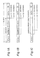
- Figures 2 to 5 show several examples of a frame format to which the invention is applicable.
- Figures 2 and 4 are frame formats which are application to transmission of audio data of one field in the NTSC system.
- Figure 2 shows a frame format in the case where one word consists of 16 bits
- Figure 4 shows a frame format in the case of 12 bits compressed from 16 bits.
- Figures 3 and 5 are frame formats applicable to the encoding of audio data of one field in the CCIR system (PAL system or SECAM system).
- Figure 3 shows a frame format in the case where one word has 16 bits
- Figure 5 shows a frame format in the one-word-16-bit case.
- the provision of 12 bits and 16 bits as the bit number of one word is to provide a different recording wavelength depending on the kind of magnetic tape to be used. For example, in the case of an evaporated metal tape, the recording/reproduction of 16-bit data is performed, while the recording/reproduction of 12-bit data is carried out in the case of a metal coating tape.
- fields having 800 words per channel and fields having 801 words per channel mixedly exist.
- Audio data are arranged in a matrix form of 40 x 80 symbols (or bytes), and four symbols which occur in the transmission of a field having 801 words are inserted into a header.
- the header includes a synchronization signal to provide 4 x 100 symbols.
- the encoding of the C1 code is performed in the vertical direction of the two-dimensional array of data and headers, and in the horizontal direction, the encoding of the C2 code is carried out. However, as stated later, no encoding is performed for the C1 code and the C2 code with respect to a synchronization signal. With respect to a redundant code of an error detection code and a part of an auxiliary code in the header, the encoding of only the C1 code is effected.
- the encoding of the C1 code and the C2 is performed on a sub-code (various ID codes, and so on) of the auxiliary code and audio data (four symbols).
- the Reed-Solomon code whose (code length, information length, distance) are 47, 43, 5, respectively, is employed, and check data P (four symbols) of the C1 code are generated.
- the size in the vertical direction is increased to be equal to 16-bit data as shown in Figure 4 to make the length in the lateral direction 3/4-ths.
- the length of the interleave in the horizontal direction is changed to be three, and for the C1 code and the C2 code, ones similar to the 16-bit data are used.
- the field frequency is 50 Hz
- data of one field have 960 words in the case of a sampling frequency of 48 kHz.
- 3840 symbols are provided. Consequently, the frame format of Figure 3 is employed.
- the longitudinal length is selected to be 48 symbols which is equal to the frame format of the NTSC system, and the horizontal size is selected to be 116 blocks.
- the interleave length in the horizontal direction is selected to be four, and as the C2 code, a Reed-Solomon code is employed.
- the horizontal length is selected to be 87 blocks, which is 3/4-ths as compared with the frame format of Figure 3.
- the interleave length of the C2 code is selected to be three, and a C2 code similar to the C2 code for the 16-bit data is used.
- the present invention is application to any one of the frame formats of Figures 2 to 5.
- the sampling frequency 48 kHz
- all the words can be arranged in the data area of the frame.
- the present invention is applicable to the case where auxiliary data such as time code are inserted into a header in a CCIR system.
- the embodiment described below is the case where the invention is applicable to the frame format ( Figure 2) of the 16-bit data in the NTSC system.
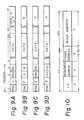
- Figure 6 shows the frame format of Figure 2 in detail.
- One block is formed by 48 symbols arranged in the vertical direction.
- a header is disposed at the head of one block.
- the header comprises a synchronization signal (one symbol) and an error check code, for the data of the header, for example, check data E or E (one symbol) of a simple parity and check data Q of the C2 code, an upper (more significant) symbol ADu of an address signal, an upper symbol SBu of a sub-code or upper symbols LOu, ROu of audio data and the check data Q of the C2 code, a lower (less significant) symbol ADl of the address signal, and a lower symbol SBl of the sub-code or lower symbols LOl ROl of the audio data.
- a data area of 44 symbols is positioned after the header.
- the data area is made up of data (audio PCM signal), check data Q and check data P.
- One frame is formed by arranging the above-mentioned blocks of 100 columns in the lateral direction. Block-in addresses l of 0 to 47 are added to 48 symbols in the longitudinal direction of the matrix-shaped frame, and block addresses k of 0 to 99 are added to 100 blocks in the horizontal direction.
- the audio PCM signal and check data P are contained in 44 symbols x 80 blocks of 20 to 99 of the block addresses k and 4 to 47 of the block-in addresses l. Since a video signal and a time-axis-compressed audio PCM signal are recorded onto a magnetic tape by a single scanning of the rotary heads, the amount of information of the audio PCM signal is contained in one field period. In the case of the sampling frequency of 48 kHz, the PCM audio signal of one field of the NTSC system are set to:
- the sampling frequency cannot be divided by the field frequency.
- the frame format of Figure 6 the cases of both 800 words and 801 words which are recorded in mixed together fashion exist during a plurality of fields.
- the frame format has 801 words. In the case of performing a linear digitization of 16 bits, each word is divided into an upper eight bits and a lower eight bits, and one symbol is set equal to eight bits.
- an error detection code a simple parity is employed.
- a CRC code, etc, may be used without being limited to the simple parity.
- an upper symbols ADu of an address signal, an upper symbols SBu of a sub-code or upper symbols LOu, ROu of an audio PCM are contained corresponding to the block address.
- the upper symbols LOu, ROu of the PCM data are disposed.
- the encoding process of the C2 code is not performed with respect to an upper symbol ADu of the address signal.
- l 3
- k 0 to 99
- a lower symbol ADl of the address signal a lower symbol SBl of the sub-code or lower symbols LOl, ROl of the sub-code are contained.
- a similar encoding process of the C2 code to the above-mentioned data of l 2 is made with respect to this data except for the lower symbol ADl of the address signal.
- the sub-codes SBu, SBl are a time code which a user can employ, ID code of tape speed upon recording, ID code of stereo or bilingual, flag indicative of copy prohibition and so on.
- no address signal is contained in a block in which the encoding of the C2 code is made in the header.
- a header in which an address signal is contained and a header in which audio data or a sub-code is included and the C2 encoding is performed are distinguished by the check data E and inverted data E .
- the C1 code is the Reed-Solomon code of 47, 43, 5.
- the series of the C1 code is constructed so as to exist in two adjacent blocks. That is, one C1 series is formed by the odd-number designated symbols of the block-in address of two adjacent blocks. Another C1′ series is formed by the even-number designated symbols of the block-in address. The reason why the C1 sequence is formed so as to exist in two blocks is to prevent two symbols in one C1 series from becoming errors due to errors generated at the boundary of two sequential symbols upon recording.
- the encoding by the C1 code is similar to the method described in US patent specification US-A-4 630 272.
- error detection and error correction are performed by the C1 code.
- a pointer is set for a block for which an error cannot be corrected, and error detection and error correction of the C2 code are made referring to the pointer.
- error detection on a header is performed by check data E and E .
- a syndrome of a block, with the check data E added has eight bits of all "0's" in the absence of an error
- a syndrome of a block, with the check data E added has eight bits of all "1's” in the absence of an error. Due to the difference of the syndrome patterns, the difference in the content of the header can be detected.
- Figures 7 and 8 show an interleave of data of 801 words (3204 symbols in two channels) of one field of the NTSC system in detail.
- the even-number designated words are arranged as shown in Figures 7C and 7D in a manner similar to the odd-number designated words.
- the recording positions of adjacent words are interleaved by four blocks. Successive recording of the upper side symbol and the lower side symbol of one word is prevented, and the influence of burst errors is reduced.
- Figures 9A to 9D shows blocks formed by each column (vertical direction) in the above-described frame format as shown in Figures 7A, 7B and 7D.
- Figure 10 shows the contents of an address signal comprising an upper symbol ADu and a lower symbol ADl.
- the upper three bits in the upper symbol ADu are used as an identification code ID for searching for a required scene in a tape, and the subsequent three bits (INTRATRACK ADDRESS) are used as a block-in address.
- the block-in address is employed for the channel identification when one track is divided into six channels, as disclosed in US patent specification US-A-4 542 419.
- the next three bits are used as a frame address.
- the frame address is employed for selecting a required frame (track) upon high speed reproduction where the scanning of a rotary head is performed over a plurality of tracks.
- a block address k is indicated by the lower seven bits in the lower symbols ADl.
- the above-mentioned identification code is used to identify the number of words contained in the frame format of the codes. Since 800 or 801 words per channel are included in the frame format in this embodiment, an identification code is used to distinguish both.
- audio data of 40 symbols at the maximum can be inserted into a header, it is possible to set an asynchronous state absorbing margin of ten words at the maximum per channel without being limited to the case where an asynchronous state absorbing margin of one word per channel is set, as in the above-mentioned embodiment.
- the foregoing margin is necessary in order to absorb the asynchronization between the video image and the audio sound which is caused by there being no integral ratio between the sampling frequency and the field frequency.
- This invention is applicable to a rotation head-type VTR which records a video signal and a PCM audio signal onto a magnetic tape by single scanning.
- a pair of rotary heads having an angular interval of 180 o therebetween and rotated at a frame frequency (29.97 Hz in the case of the NTSC system) are mounted inside a drum.
- the heads may be magnetic heads.
- the magnetic tape is run obliquely at constant speed over the angular range of equal to or larger than 210 o , with respect to its rotational circumference.
- the rotation phases of the rotary heads are controlled so as to synchronize with the video signal to be recorded and the rotary heads are servo-controlled so as to scan the track correctly upon reproduction.
- a video section and a PCM section are formed.
- the frequency multiplexed signal of an FM luminance signal, a lower frequency band converted carrier chrominance signal, an FM audio signal and a pilot signal is recorded in the video section.
- the processing of error correction encoding and the processing of time-axis compression are performed by a PCM recording processing circuit.
- the output signal of the PCM recording processing circuit is recorded in a PCM section.
- the frequency multiplexed signal and the PCM signal are alternately reproduced by the rotary heads.
- the reproduced frequency multiplexed signal is supplied to a video reproduction and processing circuit, and the PCM signal is supplied to a PCM reproduction processing circuit.
- a reproduced colour video signal and stereo audio signals L and R are derived from these reproduction and processing circuits.
- An analogue audio signal from a terminal 1 is supplied to an input terminal of an analogue-to-digital (A/D) converter 2 where the analogue audio signal is converted into a PCM signal.
- the output data of the A/D converter 2 are supplied to an adder 3.
- the address signal and the sub-code are supplied to the adder 3 from an address and sub-code generator 4, and are added to the PCM audio signal.
- the output signal from the adder 3 is used as the data inputs to RAMs 5 and 6.
- Each of the RAMs 5 and 6 has a capacity sufficient to store the symbols of one frame.
- An address generating circuit 7 and a timing generating circuit 8 are provided in conjunction with the RAMs 5 and 6 and are controlled so as to write and read-out data into and from the RAMs 5 and 6 on a symbol unit basis.
- Two RAMs 5 and 6 are employed, so that during the time when data are written into one of the RAMs, data are read out from the other RAM and error correction encoded. Also, time-axis compression processing with a compression ratio of 1/6 is effected by the RAMs 5 and 6.
- the PCM audio signal read out from one of the RAMs 5 and 6 is supplied to an encoder 14 of the C1 and C2 codes, and the parities of the C1 and C2 codes are formed. The parities are written into either one of the RAMs 5 and 6.
- a parity generating circuit 9 is provided, and check data E of an error detection code for two symbols included in a header of each block are generated.
- the check data E are supplied to a mod-2 adder 10.
- the output of a "0" data generating circuit 12 or the output of a "1" data generating circuit 13 is supplied to the adder 10 through a selector 11.
- the selector 11 selectively supplies one of "0" data or "1" data depending on a block address from the address generating circuit 7.
- the "0" data are selected by the selector 11
- the "1" data are selected by the selector 11.
- the selector 11 no alteration is made to the check data E.
- the check code E is inverted.
- the check code E or E is added to the block.
- the digital signals consisting of check data, block address, sub-code and data are read out from the RAMs 5 and 6, block by block, and they are supplied to a parallel-to-serial converter 15 where they are converted into serial data.
- the output data from the parallel-serial converter 15 is supplied to a channel encoder 16.
- the channel encoder 15 is a 8-to-10 modulator for converting 8-bit data into 10-bit data, so as to reduce the direct current component of the data sequence irrespective of the data content.
- the channel encoder 16 comprises a ROM storing a data conversion map.
- the output signal of the channel encoder 16 is supplied to a second adder 17, and in the second adder 17, a block synchronization signal from a synch generator 18 is added to the output signal and is derived as a PCM signal at an output terminal 10 via a recording amplifier 19.
- This output signal is recorded onto a magnetic tape T by rotary heads HA and HB.
- the magnetic tape T is wrapped obliquely around the peripheral surface of a drum over an angular range of 210 o .
- 800 and 801 have been used as two types of numerical value data.
- numerical values of, for example, 800 and 802 which are close to the quotient obtained when the sampling frequency fs is divided by the field frequency.
- three or more kinds of numerical values can also be selective used thereby not being limited to two kinds.
- This invention is applicable to the case where a frame of error correction codes is comprised of a unit of one word or two words of L and R.
- error correction codes other than Reed-Solomon codes can be used.
- Embodiments of this invention can prevent the increase of redundancy due to the addition of an address signal with respect to all blocks.
- such embodiments enable the formation of a plurality of contents as headers containing a synchronization signal and an address signal other than a digital information signal. Therefore, the digital information signal, a sub-code, etc, can be inserted in place of the address signal.
- the recording of a number of words, which, on an average, is equal to the quotient obtained when the sampling frequency is divided by the field frequency can be performed. The occurrence of asynchronization between a video image and audio sound can be prevented.
Landscapes
- Engineering & Computer Science (AREA)
- Signal Processing (AREA)
- Multimedia (AREA)
- Physics & Mathematics (AREA)
- Probability & Statistics with Applications (AREA)
- Theoretical Computer Science (AREA)
- Error Detection And Correction (AREA)
- Synchronisation In Digital Transmission Systems (AREA)
- Detection And Prevention Of Errors In Transmission (AREA)
- Signal Processing For Digital Recording And Reproducing (AREA)
Applications Claiming Priority (2)
| Application Number | Priority Date | Filing Date | Title |
|---|---|---|---|
| JP163667/88 | 1988-06-30 | ||
| JP63163667A JPH0213135A (ja) | 1988-06-30 | 1988-06-30 | ディジタル信号伝送装置 |
Publications (2)
| Publication Number | Publication Date |
|---|---|
| EP0349325A2 true EP0349325A2 (de) | 1990-01-03 |
| EP0349325A3 EP0349325A3 (de) | 1991-12-27 |
Family
ID=15778301
Family Applications (1)
| Application Number | Title | Priority Date | Filing Date |
|---|---|---|---|
| EP19890306628 Withdrawn EP0349325A3 (de) | 1988-06-30 | 1989-06-29 | Gerät zur Uebertragung eines digitalen Signals |
Country Status (3)
| Country | Link |
|---|---|
| EP (1) | EP0349325A3 (de) |
| JP (1) | JPH0213135A (de) |
| KR (1) | KR900001135A (de) |
Cited By (17)
| Publication number | Priority date | Publication date | Assignee | Title |
|---|---|---|---|---|
| EP0544090A1 (de) * | 1991-10-14 | 1993-06-02 | Sony Corporation | Verfahren zum Aufzeichnen eines digitalen Audiosignals auf einem Kinofilm |
| ES2068105A1 (es) * | 1992-11-30 | 1995-04-01 | Alcatel Standard Electrica | Metodo y dispositivo de deteccion y correccion de errores en cabeceras de celulas atm. |
| US5581654A (en) * | 1993-05-25 | 1996-12-03 | Sony Corporation | Method and apparatus for information encoding and decoding |
| US5583967A (en) * | 1992-06-16 | 1996-12-10 | Sony Corporation | Apparatus for compressing a digital input signal with signal spectrum-dependent and noise spectrum-dependent quantizing bit allocation |
| US5608713A (en) * | 1994-02-09 | 1997-03-04 | Sony Corporation | Bit allocation of digital audio signal blocks by non-linear processing |
| US5621489A (en) * | 1992-06-10 | 1997-04-15 | Sony Corporation | Medium having photographically recorded digital audio bits |
| US5639585A (en) * | 1995-08-31 | 1997-06-17 | Sony Corporation | System for photographically recording digital data and analog soundtrack, and medium having digital data and analog soundtrack recorded thereon |
| US5642111A (en) * | 1993-02-02 | 1997-06-24 | Sony Corporation | High efficiency encoding or decoding method and device |
| US5752224A (en) * | 1994-04-01 | 1998-05-12 | Sony Corporation | Information encoding method and apparatus, information decoding method and apparatus information transmission method and information recording medium |
| US5758316A (en) * | 1994-06-13 | 1998-05-26 | Sony Corporation | Methods and apparatus for information encoding and decoding based upon tonal components of plural channels |
| EP0844613A1 (de) * | 1996-11-22 | 1998-05-27 | THOMSON multimedia | Kodierer un Dekodierer zum Aufzeichnen und Lesen von binären Datensequenzen mit Hilfe eines digitalen Videorekorders |
| US5781586A (en) * | 1994-07-28 | 1998-07-14 | Sony Corporation | Method and apparatus for encoding the information, method and apparatus for decoding the information and information recording medium |
| US5819214A (en) * | 1993-03-09 | 1998-10-06 | Sony Corporation | Length of a processing block is rendered variable responsive to input signals |
| US5832426A (en) * | 1994-12-15 | 1998-11-03 | Sony Corporation | High efficiency audio encoding method and apparatus |
| US5930750A (en) * | 1996-01-30 | 1999-07-27 | Sony Corporation | Adaptive subband scaling method and apparatus for quantization bit allocation in variable length perceptual coding |
| USRE36559E (en) * | 1989-09-26 | 2000-02-08 | Sony Corporation | Method and apparatus for encoding audio signals divided into a plurality of frequency bands |
| US6647063B1 (en) | 1994-07-27 | 2003-11-11 | Sony Corporation | Information encoding method and apparatus, information decoding method and apparatus and recording medium |
Families Citing this family (3)
| Publication number | Priority date | Publication date | Assignee | Title |
|---|---|---|---|---|
| WO2010054701A1 (de) | 2008-11-14 | 2010-05-20 | Alfred Kärcher Gmbh & Co. Kg | Hochdruckreinigungsgerät |
| PL2396550T3 (pl) | 2009-02-13 | 2014-09-30 | Kaercher Gmbh & Co Kg Alfred | Zespół motopompy |
| WO2010091698A1 (de) | 2009-02-13 | 2010-08-19 | Alfred Kärcher Gmbh & Co. Kg | Motorpumpeneinheit |
Family Cites Families (3)
| Publication number | Priority date | Publication date | Assignee | Title |
|---|---|---|---|---|
| JP2533076B2 (ja) * | 1983-04-30 | 1996-09-11 | ソニー株式会社 | エラ−訂正のための符号化方法 |
| JPH0770177B2 (ja) * | 1984-01-25 | 1995-07-31 | 株式会社日立製作所 | ディジタル信号再生装置 |
| KR900008446B1 (ko) * | 1985-11-13 | 1990-11-22 | 가부시끼가이샤 히다찌세이사꾸쇼 | 음성신호를위한표본화주파수와회전헤드스캔너의회전주파수사이에서비동기관계를갖는음성신호의pcm기록재생장치 |
-
1988
- 1988-06-30 JP JP63163667A patent/JPH0213135A/ja active Pending
-
1989
- 1989-06-27 KR KR1019890008848A patent/KR900001135A/ko not_active Withdrawn
- 1989-06-29 EP EP19890306628 patent/EP0349325A3/de not_active Withdrawn
Cited By (21)
| Publication number | Priority date | Publication date | Assignee | Title |
|---|---|---|---|---|
| USRE36559E (en) * | 1989-09-26 | 2000-02-08 | Sony Corporation | Method and apparatus for encoding audio signals divided into a plurality of frequency bands |
| US5471263A (en) * | 1991-10-14 | 1995-11-28 | Sony Corporation | Method for recording a digital audio signal on a motion picture film and a motion picture film having digital soundtracks |
| EP0544090A1 (de) * | 1991-10-14 | 1993-06-02 | Sony Corporation | Verfahren zum Aufzeichnen eines digitalen Audiosignals auf einem Kinofilm |
| US5666185A (en) * | 1991-10-14 | 1997-09-09 | Sony Corporation | Method for recording a digital audio signal on a motion picture film |
| US5621489A (en) * | 1992-06-10 | 1997-04-15 | Sony Corporation | Medium having photographically recorded digital audio bits |
| US5583967A (en) * | 1992-06-16 | 1996-12-10 | Sony Corporation | Apparatus for compressing a digital input signal with signal spectrum-dependent and noise spectrum-dependent quantizing bit allocation |
| ES2068105A1 (es) * | 1992-11-30 | 1995-04-01 | Alcatel Standard Electrica | Metodo y dispositivo de deteccion y correccion de errores en cabeceras de celulas atm. |
| US5642111A (en) * | 1993-02-02 | 1997-06-24 | Sony Corporation | High efficiency encoding or decoding method and device |
| US5819214A (en) * | 1993-03-09 | 1998-10-06 | Sony Corporation | Length of a processing block is rendered variable responsive to input signals |
| US5581654A (en) * | 1993-05-25 | 1996-12-03 | Sony Corporation | Method and apparatus for information encoding and decoding |
| US5608713A (en) * | 1994-02-09 | 1997-03-04 | Sony Corporation | Bit allocation of digital audio signal blocks by non-linear processing |
| US5752224A (en) * | 1994-04-01 | 1998-05-12 | Sony Corporation | Information encoding method and apparatus, information decoding method and apparatus information transmission method and information recording medium |
| US5758316A (en) * | 1994-06-13 | 1998-05-26 | Sony Corporation | Methods and apparatus for information encoding and decoding based upon tonal components of plural channels |
| US6647063B1 (en) | 1994-07-27 | 2003-11-11 | Sony Corporation | Information encoding method and apparatus, information decoding method and apparatus and recording medium |
| US5781586A (en) * | 1994-07-28 | 1998-07-14 | Sony Corporation | Method and apparatus for encoding the information, method and apparatus for decoding the information and information recording medium |
| US5832426A (en) * | 1994-12-15 | 1998-11-03 | Sony Corporation | High efficiency audio encoding method and apparatus |
| US5639585A (en) * | 1995-08-31 | 1997-06-17 | Sony Corporation | System for photographically recording digital data and analog soundtrack, and medium having digital data and analog soundtrack recorded thereon |
| US5930750A (en) * | 1996-01-30 | 1999-07-27 | Sony Corporation | Adaptive subband scaling method and apparatus for quantization bit allocation in variable length perceptual coding |
| US6604069B1 (en) | 1996-01-30 | 2003-08-05 | Sony Corporation | Signals having quantized values and variable length codes |
| EP0844613A1 (de) * | 1996-11-22 | 1998-05-27 | THOMSON multimedia | Kodierer un Dekodierer zum Aufzeichnen und Lesen von binären Datensequenzen mit Hilfe eines digitalen Videorekorders |
| FR2756445A1 (fr) * | 1996-11-22 | 1998-05-29 | Thomson Multimedia Sa | Codeur et decodeur pour l'enregistrement et la lecture de trains de donnees binaires a l'aide d'un magnetoscope numerique |
Also Published As
| Publication number | Publication date |
|---|---|
| JPH0213135A (ja) | 1990-01-17 |
| EP0349325A3 (de) | 1991-12-27 |
| KR900001135A (ko) | 1990-01-31 |
Similar Documents
| Publication | Publication Date | Title |
|---|---|---|
| US5172380A (en) | Digital signal transmission apparatus | |
| EP0349325A2 (de) | Gerät zur Uebertragung eines digitalen Signals | |
| EP0348132B1 (de) | Verfahren und Gerät zur Übertragung von Daten | |
| EP0554967B1 (de) | Vorrichtung zum Übertragen eines digitalen Videosignals | |
| CA1298403C (en) | Method and apparatus for pcm recording and reproducing audio signal | |
| US4914527A (en) | Recording and reproducing digital video and audio signals together with a time code signal which is within user control words of the audio data | |
| EP0094671B1 (de) | Datenübertragungsverfahren | |
| US4630272A (en) | Encoding method for error correction | |
| EP0542576A1 (de) | Vorrichtung und Verfahren zum Aufnehmen und Wiedergeben von digitalen Video- und Audiosignalen | |
| US4819088A (en) | Magnetic recording and reproducing system | |
| US4748628A (en) | Method and apparatus for correcting errors in digital audio signals | |
| US4928185A (en) | Rotary head type recording/reproducing method and apparatus for recording and reproducing a digital audio signal | |
| CA1317025C (en) | Digital signal recording apparatus | |
| KR0139413B1 (ko) | 에러 정정 부호화 장치 | |
| US5101274A (en) | Digital signal recording apparatus time-division multiplexing video and audio signals | |
| EP0241014B1 (de) | Aufzeichnung und Wiedergabe eines Zeitkodesignals zusammen mit digitalen Video- und Tonsignalen | |
| US4809087A (en) | Apparatus for recording a discriminative signal | |
| EP0366402B1 (de) | Verfahren zur Aufzeichnung/Wiedergabe eines digitalen Audiosignals und mitgehende Einrichtung | |
| EP0621731A2 (de) | Gerät zur Aufzeichnung und Wiedergabe von digitalen Daten | |
| JP2706067B2 (ja) | デイジタルデータ符号化方式 | |
| JPH0817009B2 (ja) | ディジタル信号記録装置 |
Legal Events
| Date | Code | Title | Description |
|---|---|---|---|
| PUAI | Public reference made under article 153(3) epc to a published international application that has entered the european phase |
Free format text: ORIGINAL CODE: 0009012 |
|
| AK | Designated contracting states |
Kind code of ref document: A2 Designated state(s): DE ES FR GB NL |
|
| PUAL | Search report despatched |
Free format text: ORIGINAL CODE: 0009013 |
|
| AK | Designated contracting states |
Kind code of ref document: A3 Designated state(s): DE ES FR GB NL |
|
| STAA | Information on the status of an ep patent application or granted ep patent |
Free format text: STATUS: THE APPLICATION IS DEEMED TO BE WITHDRAWN |
|
| 18D | Application deemed to be withdrawn |
Effective date: 19920630 |