EP0349324B1 - Abnützungsresistente Prothesenvorrichtung - Google Patents
Abnützungsresistente Prothesenvorrichtung Download PDFInfo
- Publication number
- EP0349324B1 EP0349324B1 EP89306627A EP89306627A EP0349324B1 EP 0349324 B1 EP0349324 B1 EP 0349324B1 EP 89306627 A EP89306627 A EP 89306627A EP 89306627 A EP89306627 A EP 89306627A EP 0349324 B1 EP0349324 B1 EP 0349324B1
- Authority
- EP
- European Patent Office
- Prior art keywords
- prosthetic device
- strap
- sacrificial
- layer
- bearing
- Prior art date
- Legal status (The legal status is an assumption and is not a legal conclusion. Google has not performed a legal analysis and makes no representation as to the accuracy of the status listed.)
- Expired - Lifetime
Links
- 238000005299 abrasion Methods 0.000 title claims description 41
- 239000000463 material Substances 0.000 claims description 35
- 210000000988 bone and bone Anatomy 0.000 claims description 23
- -1 polypropylene Polymers 0.000 claims description 13
- 239000004743 Polypropylene Substances 0.000 claims description 9
- 229920001155 polypropylene Polymers 0.000 claims description 9
- 230000001681 protective effect Effects 0.000 claims description 7
- 239000000560 biocompatible material Substances 0.000 claims description 4
- 208000035874 Excoriation Diseases 0.000 description 36
- 239000010410 layer Substances 0.000 description 36
- 210000003041 ligament Anatomy 0.000 description 25
- 238000009958 sewing Methods 0.000 description 13
- 210000001264 anterior cruciate ligament Anatomy 0.000 description 10
- 210000002435 tendon Anatomy 0.000 description 8
- 210000003127 knee Anatomy 0.000 description 7
- 238000000034 method Methods 0.000 description 7
- 210000000689 upper leg Anatomy 0.000 description 6
- 239000011241 protective layer Substances 0.000 description 5
- 210000002303 tibia Anatomy 0.000 description 5
- 210000001519 tissue Anatomy 0.000 description 5
- 239000000835 fiber Substances 0.000 description 4
- 210000000629 knee joint Anatomy 0.000 description 3
- 229910052751 metal Inorganic materials 0.000 description 3
- 239000002184 metal Substances 0.000 description 3
- 241001465754 Metazoa Species 0.000 description 2
- 239000004677 Nylon Substances 0.000 description 2
- 230000003416 augmentation Effects 0.000 description 2
- ORQBXQOJMQIAOY-UHFFFAOYSA-N nobelium Chemical compound [No] ORQBXQOJMQIAOY-UHFFFAOYSA-N 0.000 description 2
- 229920001778 nylon Polymers 0.000 description 2
- 229920001748 polybutylene Polymers 0.000 description 2
- 241000283707 Capra Species 0.000 description 1
- 208000005137 Joint instability Diseases 0.000 description 1
- 206010070874 Joint laxity Diseases 0.000 description 1
- NRTOMJZYCJJWKI-UHFFFAOYSA-N Titanium nitride Chemical compound [Ti]#N NRTOMJZYCJJWKI-UHFFFAOYSA-N 0.000 description 1
- 239000004699 Ultra-high molecular weight polyethylene Substances 0.000 description 1
- 238000004026 adhesive bonding Methods 0.000 description 1
- 229920003235 aromatic polyamide Polymers 0.000 description 1
- 239000012237 artificial material Substances 0.000 description 1
- 238000005452 bending Methods 0.000 description 1
- 239000012620 biological material Substances 0.000 description 1
- 230000012085 chronic inflammatory response Effects 0.000 description 1
- 230000003467 diminishing effect Effects 0.000 description 1
- 238000005553 drilling Methods 0.000 description 1
- 238000011156 evaluation Methods 0.000 description 1
- 238000001125 extrusion Methods 0.000 description 1
- 239000004744 fabric Substances 0.000 description 1
- 239000010408 film Substances 0.000 description 1
- 230000002163 immunogen Effects 0.000 description 1
- 238000002513 implantation Methods 0.000 description 1
- 230000003387 muscular Effects 0.000 description 1
- 231100001223 noncarcinogenic Toxicity 0.000 description 1
- 230000002352 nonmutagenic effect Effects 0.000 description 1
- 239000004745 nonwoven fabric Substances 0.000 description 1
- 210000004417 patella Anatomy 0.000 description 1
- 210000000426 patellar ligament Anatomy 0.000 description 1
- 229920000728 polyester Polymers 0.000 description 1
- 229920000139 polyethylene terephthalate Polymers 0.000 description 1
- 239000005020 polyethylene terephthalate Substances 0.000 description 1
- 229920000098 polyolefin Polymers 0.000 description 1
- 229920001343 polytetrafluoroethylene Polymers 0.000 description 1
- 239000004810 polytetrafluoroethylene Substances 0.000 description 1
- 239000011347 resin Substances 0.000 description 1
- 229920005989 resin Polymers 0.000 description 1
- 239000002356 single layer Substances 0.000 description 1
- 238000002791 soaking Methods 0.000 description 1
- 239000000126 substance Substances 0.000 description 1
- 238000001356 surgical procedure Methods 0.000 description 1
- 239000004753 textile Substances 0.000 description 1
- 229920000785 ultra high molecular weight polyethylene Polymers 0.000 description 1
- 239000002759 woven fabric Substances 0.000 description 1
Images
Classifications
-
- A—HUMAN NECESSITIES
- A61—MEDICAL OR VETERINARY SCIENCE; HYGIENE
- A61F—FILTERS IMPLANTABLE INTO BLOOD VESSELS; PROSTHESES; DEVICES PROVIDING PATENCY TO, OR PREVENTING COLLAPSING OF, TUBULAR STRUCTURES OF THE BODY, e.g. STENTS; ORTHOPAEDIC, NURSING OR CONTRACEPTIVE DEVICES; FOMENTATION; TREATMENT OR PROTECTION OF EYES OR EARS; BANDAGES, DRESSINGS OR ABSORBENT PADS; FIRST-AID KITS
- A61F2/00—Filters implantable into blood vessels; Prostheses, i.e. artificial substitutes or replacements for parts of the body; Appliances for connecting them with the body; Devices providing patency to, or preventing collapsing of, tubular structures of the body, e.g. stents
- A61F2/02—Prostheses implantable into the body
- A61F2/08—Muscles; Tendons; Ligaments
-
- A—HUMAN NECESSITIES
- A61—MEDICAL OR VETERINARY SCIENCE; HYGIENE
- A61L—METHODS OR APPARATUS FOR STERILISING MATERIALS OR OBJECTS IN GENERAL; DISINFECTION, STERILISATION OR DEODORISATION OF AIR; CHEMICAL ASPECTS OF BANDAGES, DRESSINGS, ABSORBENT PADS OR SURGICAL ARTICLES; MATERIALS FOR BANDAGES, DRESSINGS, ABSORBENT PADS OR SURGICAL ARTICLES
- A61L27/00—Materials for grafts or prostheses or for coating grafts or prostheses
- A61L27/14—Macromolecular materials
- A61L27/16—Macromolecular materials obtained by reactions only involving carbon-to-carbon unsaturated bonds
-
- A—HUMAN NECESSITIES
- A61—MEDICAL OR VETERINARY SCIENCE; HYGIENE
- A61L—METHODS OR APPARATUS FOR STERILISING MATERIALS OR OBJECTS IN GENERAL; DISINFECTION, STERILISATION OR DEODORISATION OF AIR; CHEMICAL ASPECTS OF BANDAGES, DRESSINGS, ABSORBENT PADS OR SURGICAL ARTICLES; MATERIALS FOR BANDAGES, DRESSINGS, ABSORBENT PADS OR SURGICAL ARTICLES
- A61L27/00—Materials for grafts or prostheses or for coating grafts or prostheses
- A61L27/14—Macromolecular materials
- A61L27/18—Macromolecular materials obtained otherwise than by reactions only involving carbon-to-carbon unsaturated bonds
-
- D—TEXTILES; PAPER
- D04—BRAIDING; LACE-MAKING; KNITTING; TRIMMINGS; NON-WOVEN FABRICS
- D04C—BRAIDING OR MANUFACTURE OF LACE, INCLUDING BOBBIN-NET OR CARBONISED LACE; BRAIDING MACHINES; BRAID; LACE
- D04C1/00—Braid or lace, e.g. pillow-lace; Processes for the manufacture thereof
- D04C1/06—Braid or lace serving particular purposes
- D04C1/12—Cords, lines, or tows
-
- D—TEXTILES; PAPER
- D10—INDEXING SCHEME ASSOCIATED WITH SUBLASSES OF SECTION D, RELATING TO TEXTILES
- D10B—INDEXING SCHEME ASSOCIATED WITH SUBLASSES OF SECTION D, RELATING TO TEXTILES
- D10B2403/00—Details of fabric structure established in the fabric forming process
- D10B2403/03—Shape features
- D10B2403/031—Narrow fabric of constant width
- D10B2403/0311—Small thickness fabric, e.g. ribbons, tapes or straps
-
- D—TEXTILES; PAPER
- D10—INDEXING SCHEME ASSOCIATED WITH SUBLASSES OF SECTION D, RELATING TO TEXTILES
- D10B—INDEXING SCHEME ASSOCIATED WITH SUBLASSES OF SECTION D, RELATING TO TEXTILES
- D10B2509/00—Medical; Hygiene
Definitions
- the present invention relates a device for replacing damaged biological tissue such as ligaments and tendons.
- ACL anterior cruciate ligament
- the ACL provides knee stability by extending intra-articularly across the knee joint from the anteromedial surface of the proximal tibia to the posterolateral surface of the distal femur.
- An ACL replacement prosthesis must be implanted in the appropriate anatomical position in order to restore knee stability. This may be achieved by drilling holes in the tibia and femur that exit intra-articularly at the normal anatomic attachment sites of the ACL.
- An alternative to the femoral drill hole is to place the ACL replacement prosthesis over the lateral femoral condyle, which is often referred to as the "over-the-top" position.
- EP-A-0,067,929 discloses an artificial ligament with metal fibers arranged side-by-side so as to give a generally flat configuration.
- Plural metal fibers as load-bearing elements are covered with a textile mesh of natural silk. This mesh is selected to facilitate the in-growth of body tissue.
- the load bearing element is itself composed of metal fibers and abrasion resistance of the load bearing element is due to a titanium nitride layer.
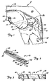
- Figure 1 is a lateral view of a knee joint showing the prosthetic ligament of the present invention in place.
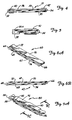
- Figure 2 is a perspective view of a preferred embodiment of the prosthetic ligament of the present invention.
- Figure 3 is a top view of the prosthetic ligament of Figure 2.
- Figure 4 is a side view of the prosthetic ligament of Figure 2.
- Figure 5 is a detail view showing one end of the prosthetic ligament of Figure 2.
- Figures 6A and 6B are perspective and side elevational views, respectively, of a second embodiment of the prosthetic ligament of the present invention.
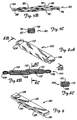
- Figure 7A, 7B and 7C are perspective, side elevational and sectional views of a third embodiment of the prosthetic ligament of the present invention.
- Figures 8A, 8B and 8C are perspective and sectional views of a fourth embodiment of the prosthetic ligament of the present invention.
- Figure 9 is a perspective view of a fifth embodiment of the prosthetic device of the present invention.
- the prosthetic device of the present invention is used as a replacement for a damaged ligament or tendon.
- the device will be surgically implanted and anchored to bone by bone screws, sutures or staples.
- FIG. 1 shows prosthetic device 10 implanted as a replacement for the anterior cruciate ligament of knee 12.
- FIG 1 shows prosthetic device 10 implanted as a replacement for the anterior cruciate ligament of knee 12.
- femur 14, tibia 16, quadriceps tendon 18, patella 20, and patellar tendon 22 are shown.
- Shown at the distal end of femur 14 are lateral femoral condyle 24, medial femoral condyle 26, and intercondylar notch 28.
- Prosthetic device 10 which is shown in further detail in Figures 2 - 5, includes a flexible load-bearing strap-like element 30 which is folded over at each end to form end loops 32 and 34 and abrasion resistant sacrificial layers or areas 36 and 38. Attachment eyelets 40 and 42 extend through loops 32 and 34, respectively.
- sacrificial layers it should be understood to refer to the sacrificial areas of the layers, since the entire layer is not sacrificial, but a major portion of the layer which is not part of the end loop is sacrificial. The end loop portion of the sacrificial layer contributes substantially to the strength of the device and should not be sacrificed.
- eyelet 42 on the tibial end of device 10 remains outside of tibial drill hole tunnel 44 and is anchored to the anteromedial surface of the tibia 16 by bone screw 46.
- Device 10 extends upward from eyelet 42 through tibial bone tunnel 44 and then across lateral femoral condyle 24. Tension is applied to the femoral end of device 10 in order to restore normal knee joint laxity, and eyelet 40 of device 10 is then anchored to a lateral surface of femur 14 by bone screw 48.
- Abrasion site 50 is located at the posterior exit of tibial bone tunnel 44.
- Abrasion site 52 is a larger area in the over-the-top region where device 10 extends over lateral femoral condyle 24. Abrasion due to friction between bone and device 10 at abrasion sites 50 and 52 occurs on opposite sides of device 10.
- femoral drill hole rather than an over-the-top attachment of device 10 will also create an abrasion site where device 10 comes into frictional contact with femur 14 at the anterior exit of the femoral bone tunnel.
- Prosthetic device 10 of the present invention is capable of withstanding substantial amounts of abrasion without significantly diminishing its load-bearing characteristics. This significantly extends the useful lifetime of prosthetic device 10 beyond the characteristics of prior art ligament and tendon prostheses.
- a unitary strap-like material is used to form load-bearing strap-like element 30, loops 32 and 34 and sacrificial layers 36 and 38.
- Strap-like element 30, which is the principal load-bearing element of device 10 is sandwiched between protective layers having sacrificial areas 36 and 38.
- Layers 36 and 38 shield load-bearing strap-like element 30 from excessive abrasion at abrasion sites 50 and 52.
- a portion of sacrificial layer 36 extending from approximately the midpoint between eyelets 40 and 42 to near eyelet 40 is positioned between strap-like element 30 and abrasion site 52.
- a portion of sacrificial layer 38 from about the midpoint of device 10 to the end of sacrificial layer 38 near eyelet 42 protects strap-like element 30 from abrasion at abrasion site 50.
- Sacrificial layers 36 and 38 are connected or bonded to strap-like element 30.
- three lines of parallel sewn stitches 54, 56, and 58 bond together strap-like element 30 and sacrificial layers 36 and 38.
- Loops 32 and 34 provide additional strength to device 10 because eyelets 40 and 42 extend through two layers of material which are folded over to provide continuous fibers at the ends of the device.
- the material is preferably formed from a braid similar to presently known ligament augmentation devices such as the Kennedy LAD® braid ligament augmentation device described in U.S. Patent Application Serial Number 840,374, which is assigned to the same assignee as the present application.
- the strap-like material is flexible and, in the preferred embodiment shown in Figure 2 - 5, is generally flat in cross-section. Other cross-sectional geometries, however, also may be used with the present invention.
- Device 10 must be biocompatible, i.e., it should be non-immunogenic, non-mutagenic, non-carcinogenic and elicit no chronic inflammatory response. To ensure biocompatibility, it is preferred to utilize suitable biomaterials which have a proven history in implanted devices.
- strap-like element 30 In addition to biocompatibility, strap-like element 30 must have sufficient tensile strength to carry the working loads normally carried by a natural ligament or tendon being replaced and low flexural rigidity so as to be flexible enough to prevent interference with the normal movement of muscular or skeletal structures connected by prosthetic device 10. Strap-like element 30 must also maintain its mechanical properties over time, i.e., exhibit resistance to fatigue and creep and be stable in the moist environment of the body.
- Materials which are suitable for fabricating the strap-like element 30 generally include synthetic polymeric materials which can be formed into high strength yarns.
- polymeric materials include, but are not limited to, polyolefins such as polypropylene, ultra high molecular weight polyethylene, and polybutylene; polyesters such as polyethylene terephthalate; polytetrafluoroethylene; and polyaramids.
- strap-like element 30 is preferably fabricated from yarns of the foregoing material. Braids, webbings or weaves of these yarns are preferred. Alternatively, some materials such as polybutylene may be fabricated into flat bands of high strength and flexibility.
- One preferred braid used for strap-like element 30 consists of 26 bundles of high tenacity (7.5 g/denier) polypropylene filaments, with each bundle containing 180 filaments. These bundles are braided into a flat strap-like structure about 2 mm thick and 14 mm wide. After forming the strap-like material of desired length and configuration, the braid is cut and the ends are sealed to prevent unraveling.
- a more open structure than that of the braid may offer certain advantages when used as strap-like element 30.
- a more open structure permits viable tissue ingrowth throughout the length of device 10.
- Sacrificial layers 38 and 40 are fastened to load-bearing strap-like element 30 by any suitable mechanical, chemical or thermal means, such as sewing, glueing, or the like.
- a preferred method of bonding or connecting together layers 30, 36 and 38 is by sewing. This sewing can be done manually, or with machine. Sewing threads of any material meeting biocompatibility criteria can be used. In the case of sewing manually, a single thread is passed through the multiple layers 36, 30, and 38 in such a way as to bond or connect together all three layers. In the case of machine sewing, a needle thread and a separate bobbin thread are used to form a lock stitch which bonds or connects the layers together. Many different stitch patterns can be used to bond the layers.
- FIGs 2 and 3 illustrate a preferred stitch pattern involving three parallel stitch lines 54, 56, and 58 along the length of device 10. Stitch lines 54, 56 and 58 are spaced equally across the width of device 10. Various sewing machines can be used for creating this pattern such as, for example, the Mitsubishi Industrial Sewing Machine Model PLK-1210.
- Protective sacrificial areas 36 and 38 protect load-bearing layer 30 against abrasion. Areas 36 and 38 can themselves be further protected at key abrasion points by a further layer of woven fabric, non-woven fabric or film material, or by the addition (for example, by soaking) of an abrasion resistant material into layers 36 and 38.
- Eyelets 40 and 42 are preferably inserted into loops 32 and 34 by starting a small opening in load-bearing strap-like element 30 and inserting the eyelet 40, 42 through the layers by compacting filaments about the eyelet 40, 42.
- Eyelets 40 and 42 may be formed of any suitable biocompatible material, and are preferably the same material as that used to form strap-like element 30. Eyelets 40 and 42 are shaped to receive and hold bone screws 46 and 48. If suturing or stapling is used, for fixation of the ends of device 10 rather than bone screws, eyelets 40 and 42 are not needed. Instead, the staples or sutures are passed through loops 32 and 34 at the opposite ends of device 10.
- FIGS 6A and 6B illustrate prosthetic device 60, which is a second embodiment of the present invention.
- a single layer of strap-like material is folded over at each end to form load-bearing strap-like element 62, end loops 64 and 66, and loop tails 68 and 70.
- Abrasion resistant sacrificial layers 72 and 74 are bonded or connected to strap-like element 62 to perform sacrificial abrasion and protection of the load-bearing characteristics of strap-like element 62.
- sacrificial layers 72 and 74 separate from the strap-like material which forms load-bearing element 62, end loops 64 and 66, and tails 68 and 70, it is possible to obtain superior abrasion resistant characteristics which may otherwise be attainable only by sacrificing other desired qualities of load-bearing element 62.
- bone screw receiving eyelets similar to eyelets 40 and 42 of Figures 2 - 5 are not shown.
- Device 60 can be attached at its opposite ends by sutures or surgical staples. Alternatively, eyelets similar to eyelets 40 and 42 of Figures 2 - 5 can be provided in device 60.
- FIGS 7A - 7C show prosthetic device 80, which is a third embodiment of the present invention.
- a continuous strap-like material is folded over to form load-bearing strap-like element 82, end loops 84 and 86, and tails 88 and 90.
- load-bearing element 82 provides the load-bearing capabilities for device 80, while protective sheath 92 acts as a sacrificial abrasion layer for protecting load-bearing element 82 from abrasion due to contact with the patient's bones.
- FIGS 8A - 8C show prosthetic device 100, which is still another embodiment of the present invention.
- a continuous strap-like material is folded to produce a load-bearing strap-like element 102, end loops 104 and 106, and tails 108 and 110.
- Protective sleeve 112 extends around the strap-like material so that only end loops 104 and 106 extend out opposite ends of sleeve 112.
- the device is bonded together so that sleeve 112 is attached to the strap-like material forming strap-like element 102 and tails 108 and 110.
- Figure 9 illustrates prosthetic device 120, which is formed by a strap-like material doubled over to form upper and lower load-bearing layers 122 and 124 and end loop 126. Eyelet 128 extends through layers 122 and 124 at the end near loop 126. Sacrificial protective layer 130 is attached to the surface of load-bearing layer 124 from about the mid-point of device 120 to near the end containing eyelet 128.
- Device 120 as shown in Figure 9, is useful where attachment is to be made at one end with a bone screw, and by sutures or surgical staples at an opposite end. Device 120 is also intended for those applications where an abrasion site will occur on only one side of the device. In other words, the articular application for device 120 will be typically different from the use of device 10 shown in Figure 1 (where there are abrasion sites at different locations and on opposite sides of device 10).
- An abrasion resistant ligament generally of the type shown in Figures 2 - 5 was made as a flat braid constructed from bundles of polypropylene filaments.
- the filaments were formed by die extrusion of a polypropylene resin into a bundle of 180 filaments approximately 35 microns in diameter.
- the filament bundle had a tenacity of greater than 7.5 grams per denier.
- the flat braid was then fabricated in an 8 mm width containing 13 bundles of filaments.
- the braid thickness was approximately 1.5 mm.
- the prosthetic device wae constructed, in accordance with Figures 2 -5, by folding the braid into three layers and sewing the layers together using polypropylene thread. At the end of the sewing area, the braid was cut and heat sealed to prevent unraveling. Using this procedure, end loops 32 and 34 were formed, one at each end of the device as shown in Figures 2 -5. In this particular example, eyelets 40 and 42, shown in Figures 1 - 5 were not provided.
- the strength of the device was determined to be about 3300 N using the loop ends for tensile loading.
- Example 1 Using the procedure of Example 1, a prosthetic device similar to device 10 of Figures 2 - 5 (including eyelets 40 and 42) was fabricated. Eyelets 40 and 42 were inserted through both layers in each loop section 32 and 34, respectively. The eyelets 40 and 42 were machined from a block of polypropylene into a shape that conformed with the head of a bone screw to be used for fixation. Placing the eyelets 40 and 42 through loops 32 and 34 at the ends of device 10 provided a high strength anchor for attachment to bone.
- the strength of the device was determined to be 1800 N using the eyelets for tensile loading.
- An additional device was prepared in the same manner and subjected to four million cycles of dynamic tensile loading and bending. The device exhibited no loss of strength, even though some abrasion was evident on protective layers 36 and 38.
- Example 2 Using the procedure of Example 2, a stronger device was prepared using a bulkier polypropylene braid that contained 26 bundles of the same filaments (rather than 13 bundles as used in examples 1 and 2). The strength of the device was determined to be 4500 N using the eyelets for tensile loading. This strength was sufficient to cause failure of the bone screws which were used for fixation before the device itself failed.
- Example 2 Using the procedure of Example 1, an abrasion resistant device was made. The device was then covered with an additional protective layer in the form of a tubular braid of polypropylene surrounding the device and sewn to the device as illustrated in Figures 8A - 8C. The sewing was done with a sewing machine. The resulting structure was that of prosthetic device 100 illustrated in Figures 8A -8C.
- a device was made in a form similar to device 10 of Figure 2, except the eyelets 40 and 42 were not provided in the loop ends.
- Nylon thread was used to sew the layers together. The sewing on each side extended only from the looped end to the center of the device. This simulates a complete loss of the sacrificial protective layer.
- the stength of the device was determined to be 1200 N, using the loops for tensile loading. This experiment demonstrated that the strength of the prosthetic device is in the strap-like element, and that the sacrificial layers do not significantly contribute to the strength of the device.
- a device made following the procedure of example 2 was used as a prosthetic replacement of the anterior cruciate ligament in a goat. Standard surgical practices were used in this replacement. The animal was allowed to recover and was maintained for two weeks, during which time the device functioned satisfactorily as a ligament replacement. In other words, it restored normal joint stability and range of joint motion. After two weeks, the animal was sacrificed, and the device was removed for evaluation. Gross examination of the knee showed the device to be well tolerated by the tissues. The device showed very slight wear of the protective sacrificial layer in the area of contact with the tibia, and was otherwise unaffected by the two week implantation.
- the prosthetic device of the present invention offers significant advantages over prior art ligament and tendon prostheses.
- the device is protected from strength loss due to abrasion until a significiant amount of material has been lost due to abrasion.
- the device provides distinct areas for sacrificial abrasion.
- two distinct areas for sacrificial abrasion located on opposite sides of the device accomodate the two areas where abrasion against bone will occur.
- the present invention also accomodates the use of high strength eyelets, which facilitate fixation of the prosthetic ligament to bone during surgery.
Landscapes
- Health & Medical Sciences (AREA)
- Chemical & Material Sciences (AREA)
- Animal Behavior & Ethology (AREA)
- Public Health (AREA)
- Veterinary Medicine (AREA)
- Oral & Maxillofacial Surgery (AREA)
- Transplantation (AREA)
- Engineering & Computer Science (AREA)
- Life Sciences & Earth Sciences (AREA)
- General Health & Medical Sciences (AREA)
- Dermatology (AREA)
- Epidemiology (AREA)
- Medicinal Chemistry (AREA)
- Chemical Kinetics & Catalysis (AREA)
- Biomedical Technology (AREA)
- Cardiology (AREA)
- Orthopedic Medicine & Surgery (AREA)
- Heart & Thoracic Surgery (AREA)
- Rehabilitation Therapy (AREA)
- Rheumatology (AREA)
- Vascular Medicine (AREA)
- Manufacturing & Machinery (AREA)
- Textile Engineering (AREA)
- Prostheses (AREA)
Claims (19)
- Prothesenvorrichtung, umfassend:
ein flexibles, lasttragendes riemenartiges Element (30) aus einem stabilen biologisch verträglichen Material, wobei das riemenartige Element ein erstes und ein zweites Ende zur Befestigung an einem Patienten besitzt;
gekennzeichnet durch:
eine erste Schutzschicht (38) aus dem gleichen Material wie das riemenartige Element, wobei die Schicht an dem riemenartigen Element (30) an einer Stelle angebracht ist, wo es zum Abrieb zwischen der Prothesenvorrichtung und einem Knochen des Patienten kommt, wobei es bei der ersten Schutzschicht (38) zu einem Abrieb kommen kann, der die lasttragenden Eigenschaften des riemenartigen Elements nicht wesentlich ändert. - Prothesenvorrichtung nach Anspruch 1, dadurch gekennzeichnet, daß das riemenartige Element (30) an seinem ersten Ende umgelegt ist, um die lasttragende Hauptschicht, eine erste Schlinge (32) und einen ersten Schwanzabschnitt (38) zu bilden, wobei der erste Schwanzabschnitt an der lasttragenden Hauptschicht (30) befestigt ist.
- Prothesenvorrichtung nach Anspruch 2, dadurch gekennzeichnet, daß das riemenartige Element (30) an seinem zweiten Ende umgelegt ist, um eine zweite Schlinge (34) und einen zweiten Schwanzabschnitt (36) zu bilden, wobei der zweite Schwanzabschnitt an der lasttragenden Hauptschicht (30) befestigt ist.
- Prothesenvorrichtung nach Anspruch 2, dadurch gekennzeichnet, daß der erste Schwanzabschnitt (38) an der ersten Oberfläche der lasttragenden Hauptschicht befestigt ist, und der zweite Schwanzabschnitt (36) an der zweiten Oberfläche der lasttragenden Hauptschicht befestigt ist.
- Prothesenvorrichtung nach Anspruch 4, dadurch gekennzeichnet, daß die erste Schutzschicht (38) einstückig mit dem ersten Schwanzabschnitt (38) ausgebildet ist und über diesen hinausragt, um einen Abschnitt der ersten Oberfläche der lasttragenden Hauptschicht (30) zu bedecken.
- Prothesenvorrichtung nach Anspruch 4 und des weiteren umfassend:
eine zweite Schutzschicht (36), die auf die zweite Oberfläche der lasttragenden Hauptschicht (30) aufgebracht ist. - Prothesenvorrichtung nach Anspruch 6, dadurch gekennzeichnet, daß die zweite Schutzschicht (36) einstückig mit dem zweiten Schwanzabschnitt (36) ausgebildet ist und über diesen hinausragt, um einen Abschnitt der zweiten Oberfläche der lasttragenden Hauptschicht (30) zu bedecken.
- Prothesenvorrichtung nach Anspruch 7, dadurch gekennzeichnet, daß die erste und die zweite Schutzschicht und der erste und der zweite Schwanzabschnitt durch Stiche (54, 56, 58) an der lasttragenden Hauptschicht befestigt sind.
- Prothesenvorrichtung nach Anspruch 7, dadurch gekennzeichnet, daß die lasttragende Hauptschicht (30), die erste und die zweite Schlinge (32, 34), der erste und der zweite Schwanzabschnitt (38, 36), und die erste und die zweite Schutzschicht (38, 36) aus einem durchgehenden Stück eines biologisch verträglichen Materials bestehen.
- Prothesenvorrichtung nach Anspruch 9 und des weiteren umfassend:
eine erste ösenartige Befestigungsvorrichtung (40), die durch zwei die erste Schlinge bildende Materialschichten reicht; und
eine zweite ösenartige Befestigungsvorrichtung (42), die durch zwei die zweite Schlinge bildende Materialschichten reicht. - Prothesenvorrichtung nach Anspruch 9, dadurch gekennzeichnet, daß das biologisch verträgliche Material ein geflochtenes Material ist.
- Prothesenvorrichtung nach Anspruch 11, dadurch gekennzeichnet, daß das geflochtene Material aus einem synthetischen polymeren Material hergestellt ist.
- Prothesenvorrichtung nach Anspruch 12, dadurch gekennzeichnet, daß das synthetische polymere Material Polypropylen ist.
- Prothesenvorrichtung nach Anspruch 4 und des weiteren umfassend:
eine erste ösenartige Befestigungsvorrichtung (40), die durch zwei die erste Schlinge bildende Materialschichten reicht; und
eine zweite ösenartige Befestigungsvorrichtung (42), die durch zwei die zweite Schlinge bildende Materialschichten reicht. - Prothesenvorrichtung nach Anspruch 4, dadurch gekennzeichnet, daß die erste Schutzschicht (112) Teil einer Schutzhülle ist, die die erste Oberfläche der lasttragenden Hauptschicht (102) und den ersten Schwanzabschnitt bedeckt und daran befestigt ist, und die die zweite Oberfläche der lasttragenden Hauptschicht (102) und den zweiten Schwanzabschnitt (108) bedeckt und daran befestigt ist.
- Prothesenvorrichtung nach Anspruch 15, dadurch gekennzeichnet, daß die Schutzhülle eine Hülle (112) ist, die über dem riemenartigen Element positioniert ist, so daß die erste Schlinge (104) aus einem ersten Ende der Hülle herausragt, und die zweite Schlinge (106) aus dem zweiten Ende der Schlinge herausragt.
- Prothesenvorrichtung nach Anspruch 2 und des weiteren umfassend:
eine erste ösenartige Befestigungsvorrichtung (40), die durch zwei die erste Schlinge bildende Materialschichten reicht. - Prothesenvorrichtung nach Anspruch 1 und des weiteren umfassend:
eine zweite Schutzschicht (72, 74), die an dem riemenartigen Element an einer zweiten Position befestigt ist, wo es zum Abrieb zwischen der Prothesenvorrichtung und einem Knochen des Patienten kommt, wobei es bei der zweiten Schutzschicht zu einem Abrieb kommen kann, der die lasttragenden Eigenschaften des riemenartigen Elements nicht wesentlich ändert. - Prothesenvorrichtung nach Anspruch 1, dadurch gekennzeichnet, daß das riemenartige Element (30) aus einem biologisch verträglichen synthetischen polymeren Material besteht.
Applications Claiming Priority (2)
| Application Number | Priority Date | Filing Date | Title |
|---|---|---|---|
| US21469988A | 1988-07-01 | 1988-07-01 | |
| US214699 | 1988-07-01 |
Publications (2)
| Publication Number | Publication Date |
|---|---|
| EP0349324A1 EP0349324A1 (de) | 1990-01-03 |
| EP0349324B1 true EP0349324B1 (de) | 1994-02-09 |
Family
ID=22800098
Family Applications (1)
| Application Number | Title | Priority Date | Filing Date |
|---|---|---|---|
| EP89306627A Expired - Lifetime EP0349324B1 (de) | 1988-07-01 | 1989-06-29 | Abnützungsresistente Prothesenvorrichtung |
Country Status (5)
| Country | Link |
|---|---|
| EP (1) | EP0349324B1 (de) |
| JP (1) | JPH0252648A (de) |
| AU (1) | AU613500B2 (de) |
| CA (1) | CA1318466C (de) |
| DE (1) | DE68912978T2 (de) |
Families Citing this family (13)
| Publication number | Priority date | Publication date | Assignee | Title |
|---|---|---|---|---|
| FR2683716B1 (fr) * | 1991-11-18 | 1994-01-21 | Jacques Bahuaud | Greffon renforce pour ligamentoplastie du genou. |
| FR2722976A1 (fr) * | 1994-07-29 | 1996-02-02 | Hi Tec Textile Sa | Prothese de renfort de ligament et son applicateur |
| US6179840B1 (en) | 1999-07-23 | 2001-01-30 | Ethicon, Inc. | Graft fixation device and method |
| KR100566727B1 (ko) | 2002-02-26 | 2006-04-03 | 미쓰이 가가쿠 가부시키가이샤 | 올레핀계 열가소성 엘라스토머 조성물의 제조방법 |
| US20040078090A1 (en) | 2002-10-18 | 2004-04-22 | Francois Binette | Biocompatible scaffolds with tissue fragments |
| US8226715B2 (en) * | 2003-06-30 | 2012-07-24 | Depuy Mitek, Inc. | Scaffold for connective tissue repair |
| US10583220B2 (en) | 2003-08-11 | 2020-03-10 | DePuy Synthes Products, Inc. | Method and apparatus for resurfacing an articular surface |
| JP4793985B2 (ja) * | 2004-01-23 | 2011-10-12 | ニプロ株式会社 | 腱もしくは靱帯組織再生器具 |
| US11395865B2 (en) | 2004-02-09 | 2022-07-26 | DePuy Synthes Products, Inc. | Scaffolds with viable tissue |
| US20100145367A1 (en) * | 2007-02-14 | 2010-06-10 | Anthony Ratcliffe | Synthetic structure for soft tissue repair |
| DE102011083388B4 (de) * | 2010-11-26 | 2017-01-05 | Guido Wohlgemuth | Gelenkprothese |
| ITUB20151239A1 (it) * | 2015-05-29 | 2016-11-29 | Antonio Sambusseti | Protesi di legamento |
| CN106975104A (zh) * | 2016-01-19 | 2017-07-25 | 苏州微创脊柱创伤医疗科技有限公司 | 一种人工韧带编织物及其制备方法和用途 |
Family Cites Families (3)
| Publication number | Priority date | Publication date | Assignee | Title |
|---|---|---|---|---|
| CH651463A5 (de) * | 1981-06-24 | 1985-09-30 | Sulzer Ag | Sehnen- und/oder baenderersatz. |
| EP0172279A1 (de) * | 1984-08-13 | 1986-02-26 | John Augustin Jurgutis | Ersatz für menschliche Sehnenbänder |
| US4731084A (en) * | 1986-03-14 | 1988-03-15 | Richards Medical Company | Prosthetic ligament |
-
1989
- 1989-06-27 CA CA000604073A patent/CA1318466C/en not_active Expired - Fee Related
- 1989-06-28 AU AU37118/89A patent/AU613500B2/en not_active Ceased
- 1989-06-29 EP EP89306627A patent/EP0349324B1/de not_active Expired - Lifetime
- 1989-06-29 DE DE68912978T patent/DE68912978T2/de not_active Expired - Fee Related
- 1989-06-30 JP JP1167209A patent/JPH0252648A/ja active Pending
Also Published As
| Publication number | Publication date |
|---|---|
| EP0349324A1 (de) | 1990-01-03 |
| DE68912978T2 (de) | 1994-09-15 |
| DE68912978D1 (de) | 1994-03-24 |
| AU613500B2 (en) | 1991-08-01 |
| JPH0252648A (ja) | 1990-02-22 |
| CA1318466C (en) | 1993-06-01 |
| AU3711889A (en) | 1990-01-04 |
Similar Documents
| Publication | Publication Date | Title |
|---|---|---|
| US5026398A (en) | Abrasion resistant prosthetic device | |
| US4932972A (en) | Prosthetic ligament | |
| EP0304268B1 (de) | Permanente Bandprothese | |
| US5078745A (en) | Synthetic ligament for the knee | |
| US4883486A (en) | Prosthetic ligament | |
| EP0349324B1 (de) | Abnützungsresistente Prothesenvorrichtung | |
| US7905918B2 (en) | Elastic metallic replacement ligament | |
| US5108433A (en) | Tensioning means for prosthetic devices | |
| US5002574A (en) | Tensioning means for prosthetic devices | |
| JP5615891B2 (ja) | 腱の人工装具およびその製造方法 | |
| US12357447B2 (en) | Systems and methods for preparing reinforced graft constructs | |
| US4795466A (en) | Artificial crucial ligament for a knee joint | |
| WO2021138536A1 (en) | Knotless methods and constructs for tissue repairs and reconstructions | |
| JP5397801B2 (ja) | 靱帯結合材 | |
| EP3476304B1 (de) | Einheit aus nahtfaden und nadel | |
| JP3090439B2 (ja) | 円環状人工靱帯 | |
| RU2289361C1 (ru) | Эндопротез для замещения поврежденных связок и сухожилий | |
| WO1991007145A1 (en) | Prosthetic ligament | |
| WO1990002532A1 (en) | Artificial ligaments | |
| US20250195205A1 (en) | Reinforced medical implant and method of use | |
| JP7212769B2 (ja) | バックストップローダー | |
| Duval et al. | A classification of prosthetic ligament failures | |
| CS272105B1 (cs) | Pletený implantát ze syntetických nití, vhodný jako umělá náhrada šlach nebo vazů |
Legal Events
| Date | Code | Title | Description |
|---|---|---|---|
| PUAI | Public reference made under article 153(3) epc to a published international application that has entered the european phase |
Free format text: ORIGINAL CODE: 0009012 |
|
| AK | Designated contracting states |
Kind code of ref document: A1 Designated state(s): CH DE FR GB IT LI SE |
|
| 17P | Request for examination filed |
Effective date: 19900607 |
|
| 17Q | First examination report despatched |
Effective date: 19910802 |
|
| GRAA | (expected) grant |
Free format text: ORIGINAL CODE: 0009210 |
|
| AK | Designated contracting states |
Kind code of ref document: B1 Designated state(s): CH DE FR GB IT LI SE |
|
| ITF | It: translation for a ep patent filed | ||
| REF | Corresponds to: |
Ref document number: 68912978 Country of ref document: DE Date of ref document: 19940324 |
|
| ET | Fr: translation filed | ||
| PLBE | No opposition filed within time limit |
Free format text: ORIGINAL CODE: 0009261 |
|
| STAA | Information on the status of an ep patent application or granted ep patent |
Free format text: STATUS: NO OPPOSITION FILED WITHIN TIME LIMIT |
|
| EAL | Se: european patent in force in sweden |
Ref document number: 89306627.4 |
|
| 26N | No opposition filed | ||
| PGFP | Annual fee paid to national office [announced via postgrant information from national office to epo] |
Ref country code: SE Payment date: 19950511 Year of fee payment: 7 Ref country code: CH Payment date: 19950511 Year of fee payment: 7 |
|
| PGFP | Annual fee paid to national office [announced via postgrant information from national office to epo] |
Ref country code: FR Payment date: 19950526 Year of fee payment: 7 Ref country code: DE Payment date: 19950526 Year of fee payment: 7 |
|
| PGFP | Annual fee paid to national office [announced via postgrant information from national office to epo] |
Ref country code: GB Payment date: 19950530 Year of fee payment: 7 |
|
| PG25 | Lapsed in a contracting state [announced via postgrant information from national office to epo] |
Ref country code: GB Effective date: 19960629 |
|
| PG25 | Lapsed in a contracting state [announced via postgrant information from national office to epo] |
Ref country code: SE Effective date: 19960630 Ref country code: LI Effective date: 19960630 Ref country code: CH Effective date: 19960630 |
|
| REG | Reference to a national code |
Ref country code: CH Ref legal event code: PL |
|
| GBPC | Gb: european patent ceased through non-payment of renewal fee |
Effective date: 19960629 |
|
| PG25 | Lapsed in a contracting state [announced via postgrant information from national office to epo] |
Ref country code: FR Effective date: 19970228 |
|
| PG25 | Lapsed in a contracting state [announced via postgrant information from national office to epo] |
Ref country code: DE Effective date: 19970301 |
|
| EUG | Se: european patent has lapsed |
Ref document number: 89306627.4 |
|
| REG | Reference to a national code |
Ref country code: FR Ref legal event code: ST |
|
| PG25 | Lapsed in a contracting state [announced via postgrant information from national office to epo] |
Ref country code: IT Free format text: LAPSE BECAUSE OF NON-PAYMENT OF DUE FEES;WARNING: LAPSES OF ITALIAN PATENTS WITH EFFECTIVE DATE BEFORE 2007 MAY HAVE OCCURRED AT ANY TIME BEFORE 2007. THE CORRECT EFFECTIVE DATE MAY BE DIFFERENT FROM THE ONE RECORDED. Effective date: 20050629 |