EP0349212A2 - Nadeldruckkopf - Google Patents
Nadeldruckkopf Download PDFInfo
- Publication number
- EP0349212A2 EP0349212A2 EP89306383A EP89306383A EP0349212A2 EP 0349212 A2 EP0349212 A2 EP 0349212A2 EP 89306383 A EP89306383 A EP 89306383A EP 89306383 A EP89306383 A EP 89306383A EP 0349212 A2 EP0349212 A2 EP 0349212A2
- Authority
- EP
- European Patent Office
- Prior art keywords
- head according
- movable
- movable armature
- cores
- armatures
- Prior art date
- Legal status (The legal status is an assumption and is not a legal conclusion. Google has not performed a legal analysis and makes no representation as to the accuracy of the status listed.)
- Ceased
Links
Images

Classifications
-
- B—PERFORMING OPERATIONS; TRANSPORTING
- B41—PRINTING; LINING MACHINES; TYPEWRITERS; STAMPS
- B41J—TYPEWRITERS; SELECTIVE PRINTING MECHANISMS, i.e. MECHANISMS PRINTING OTHERWISE THAN FROM A FORME; CORRECTION OF TYPOGRAPHICAL ERRORS
- B41J2/00—Typewriters or selective printing mechanisms characterised by the printing or marking process for which they are designed
- B41J2/22—Typewriters or selective printing mechanisms characterised by the printing or marking process for which they are designed characterised by selective application of impact or pressure on a printing material or impression-transfer material
- B41J2/23—Typewriters or selective printing mechanisms characterised by the printing or marking process for which they are designed characterised by selective application of impact or pressure on a printing material or impression-transfer material using print wires
- B41J2/27—Actuators for print wires
- B41J2/275—Actuators for print wires of clapper type
-
- B—PERFORMING OPERATIONS; TRANSPORTING
- B41—PRINTING; LINING MACHINES; TYPEWRITERS; STAMPS
- B41J—TYPEWRITERS; SELECTIVE PRINTING MECHANISMS, i.e. MECHANISMS PRINTING OTHERWISE THAN FROM A FORME; CORRECTION OF TYPOGRAPHICAL ERRORS
- B41J2/00—Typewriters or selective printing mechanisms characterised by the printing or marking process for which they are designed
- B41J2/22—Typewriters or selective printing mechanisms characterised by the printing or marking process for which they are designed characterised by selective application of impact or pressure on a printing material or impression-transfer material
- B41J2/23—Typewriters or selective printing mechanisms characterised by the printing or marking process for which they are designed characterised by selective application of impact or pressure on a printing material or impression-transfer material using print wires
- B41J2/235—Print head assemblies
Definitions
- the present invention relates to a needle printing head of the kind set forth in the pre-characterizing part of claim 1.
- Printing heads of the above-defined type are used generally in present-day needle printers.
- the main requirement of such heads is that of providing a high rate of printing with moderate powers of excitation of the electromagnets.
- To achieve that aim it is necessary for the movable parts to be light and for the air gap between cores and movable armatures to be very limited. That is in conflict with the need to have a level of printing energy sufficient for printing a plurality of copies and a relatively long travel movement on the part of the needles.
- One object of the present invention is therefore to provide a printing head having a high level of magnetic efficiency for reducing the dimensions of the movable parts and attaining high printing rates.
- a further object is to provide sufficiently high levels of printing energy and sufficiently long travel movements on the part of the needles.
- the present invention provides a printing head as defined in claim 1.
- a further object of the invention is to provide a printing head which is of a very simple design configuration and in which the printing needles are guided and are returned to the rest condition in a highly reliable fashion.
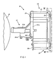
- the printing head is indicated by reference numeral 10 and comprises a front portion (nose) 11 which is intended to be directed towards a platen roller 12, an intermediate portion 13 and a rear portion 14.
- the front portion or nose 11 comprises a tubular housing 15 provided with a lower flange 15a and rear flanges 15b.
- the lower flange 15a is provided for fixing the head 10 to a carriage (not shown) which is arranged to be moved transversely in front of the roller 12 and the rear flange 15b connect the nose 11 to the intermediate portion 13.
- the nose 11 Fixed within the nose 11 are plurality of transverse walls 15c, 15d and 15e comprising guide holes which support a plurality of printing needles or wires 16.
- the needles 16 are finally guided adjacent to the roller 12 by a guide matrix 15f of hard material which is fixed to the front portion of the nose 11 in a manner known in the art.
- the nose 11 comprises an upper opening which is closed by a cover 11a fitted between the front portions of the nose and the rear flanges 15b thereof.
- the intermediate portion 13 of the head 10 includes within same a plurality of electromagnets or solenoids 17 comprising fixed cores 18 and movable armatures 19 operable to actuate the needles 16 for the printing operation.
- the cores 18 are mounted within a containment body 21 and the needles 16 can be displaced longitudinally by the movable armatures 19 for the printing operation.
- the nose 11 is fixed at the rear to the containment body 21 by means of screws 23.
- the rear portion 14 of the head 10 comprises a cover 24 which is fixed to the body 21 by means of screws 26, which provides for urging a part of the armatures 19 towards the cores 18, as will be described hereinafter.
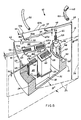
- the cores 18 are formed by a pack of ferro-cobalt plates with two limbs 27 and 28 to define a generally U-shaped configuration.
- the containment body 21 is of a cup-shaped form and is defined by a tubular outside wall 29 and a front wall 31 and contains within same a tubular projection 32.
- the cores 18 (see Figures 4 and 6) are fixed by their limbs 27 to inward recesses 33 in the tubular wall 29 and form a ring within the wall 29.
- the limbs 27 are located in the peripheral portion of the head 10 and the limbs 28 are disposed adjacent to the projection 32.
- the cores 18 also define central planes 31 which pass through a longitudinal axis 36 of the head 10 and which are angularly spaced at a constant pitch.
- the head comprises twenty four needles 16 and the planes 34 of the cores 18 are thus spaced at 15°.
- each of the cores 18 Fixed on the inward limb 28 of each of the cores 18 are corresponding excitation coils 37.
- the assembly formed by the cores 18 and the coils 37 is encased in a potting mass of resin 38 (see Figure 2) which fills the space between the inward walls of the body 21 and the cores 18 with the respective coils 37 in the manner described in the present applicants' Italian patent application No 68141-A/87 filed on 29th December 1987 (EPA 88 830 566.1).
- leads of the coils 37 which are indicated at 39, pass through corresponding openings in the front wall 31 and are soldered to terminals of a closure plate 35 of plastics material, in a similar manner to the arrangement described in above-referenced patent application.
- the limbs 27 and 28 of the cores 18 are delimited by terminal surfaces 41 and 42 respectively which, after the cores are assembled to the body 21, are disposed in the same plane 43 which is perpendicular to the longitudinal axis 36.
- a thin separating disc 40 of kapton Interposed between the terminal surfaces 41 and 42 and the respective movable armatures 19 is a thin separating disc 40 of kapton, which performs an anti-adhesion function.
- the movable armatures 19 are formed by plates of ferro-magnetic material such as a ferro-cobalt alloy and each has a magnetic flux-closure surface 44 which faces towards the terminal surfaces 41 and 42 of the cores 18.
- the armatures 19 (see Figure 6) are of an elongate rectangular shape and have one end 45 with a step configuration 46.
- An opposite end 47 of each armature 19 is tapered and fixed by means of welding to a limb 48 formed by a thin steel plate perpendicular to the surface 44.
- the limb 48 Fixed by welding to one end 49 of the limb 48 is an end of a corresponding needle 16.
- the limb 48 is very light and is of such a shape as to be of a decreasing section from the region at which it is welded to the end 47, to the region in which it is welded to the needle 16.
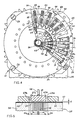
- each movable armature 19 When the head 10 is in the assembled condition the movable armatures 19 (see Figure 4) are in a star-like configuration and each movable armature is disposed symmetrically with respect to the central plane 34 of the associated core 18.
- a ring 51 of resilient material for example silicone rubber, is accommodated in a recess 52 (see also Figure 3) in the cover 24 and acts on the armatures 19 in such a way as to cause the respective step configurations 46 to bear against the terminal surfaces 41 of the cores 18.
- a second ring 53 which is also of resilient material is accommodated in a recess 54 in the cover 24 in the vicinity of the ends 49 of the limbs 48.
- each of the limbs 48 is guided, on the same axis as the respective planes 34, by corresponding ribs 56 of a guide body 57.
- the guide body is of an annular shape, is made of low-friction plastics material and is engaged in a seat 32′ in the tubular projection 32 on the containment body 21. The angular position thereof is unambiguously defined with respect to the cores 18 by a key 55 engaged in a recess 55′ in the tubular projection 32.
- the guide body 57 has cylindrical spaces 58 in which return springs 59 are disposed.
- the springs 58 urge the respective limbs 48 towards the cover 24 until they come to bear against the ring 53.
- the surface 44 of the armature 19 and the terminal surface 42 of the limb 28 define the main air gap "G" of the solenoid 17.
- the rest position of the needles 16 and the air gap "G" depend on the thickness of the ring 53 and are precisely adjusted by a series of discs 60 of mylar which are disposed in the bottom of the recess 54 and the number of which defines the operating travel of the needles.
- the head 10 for each movable armature 19, the head 10 comprises a pair of projections 62 of ferro-magnetic material, for example pure iron, which are delimited by lateral surfaces 63a and 63b (see Figure 6) which are parallel to the central plane 34 of the respective core 18 and which are spaced from the surfaces 41 and 42.
- the projections 62 are interconnected by intermediate portions 64 and are produced, for example by cutting a plate, in the form of spokes of substantially triangular shape of a conducting disc 66 which is common to all the solenoids 17.
- the disc 66 comprises in particular an outer peripheral annular portion 65 which forms the intermediate portions 64 of the projections 62 and in which the projections 62 are directed towards the longitudinal axis 36, when the head 10 is in the assembled condition.
- the movable armatures 19 with their lateral edges as indicated at 67a and 67b are capable of moving between the lateral edges 63a and 63b of the projections or spokes 62.
- the surfaces 63a and 63b and the edges 67a and 67b represent the auxiliary air gaps "Ga” and "Gb” (see Figure 5) with respect to the main air gap "G”.
- the annular portion 65 is provided with holes 68 which are precisely connected to pins 70 which are fixed on the body 21.
- the disc 66 is of a thickness "Sd" which is comparable to the thickness "Sa” of the movable armatures 19.
- the ring 51 besides acting on the armatures 19, also provides for urging the disc 66 against an edge 71 of the wall 29 of the body 21 and the peripheral annular portion 65 is disposed in front of a part (about 30%) of the terminal surface 41 of the outward limbs 27 of the cores 18.
- each armature 19 comprises two lateral projections 72a and 72b which are engaged in two corresponding lateral openings 73a and 73b in the seats 69. That makes it possible to retain the movable armatures 19 and thus the needles 16 in a fixed radial position which is clearly defined with respect to the axis 36.
- the armatures 19 according to the invention are of a width "Wa” which is comparable to the width "Wc" of the surfaces 41 and 42 of the cores 18.
- the air gaps "Ga” and “Gb” reduce the reluctance of the magnetic circuit formed by the core 18 and the armature 19 and improve the level of magnetic efficiency. With the materials used, the energy transferred to the needles 16 and the travel movement of the needles being the same, the weight of the armatures 19 can therefore be reduced in comparison with the known arrangement of the state of the art, permitting an increase in the frequency of activation of the needles.
- the thickness "Sd” and Sa” are respectively 1.5 mm and 1.6 mm.
- the separation disc 40 is of a thickness of 0.03 mm and the air gap “G” is 0.15 to 0.20 mm.
- the limbs 48 are of a thickness of 0.30 mm and the needles are 0.25 mm in diameter.
- the armatures are wider than the surfaces 41 by about 40% in such a way that the distance between the surfaces 63a and 63b and the surfaces 41 and 42 is much greater than the air gaps "G", "Ga” and “Gb".
- the widths "Wc" and “Wa” are respectively 2.1 mm and 3 mm and the distance between the surfaces 63a and 63b of the spokes 62 is 3.3 mm, when the air gaps "Ga” and "Gb" are 0.15 mm.
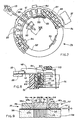
- Figure 9 shows a highly efficient alternative construction in which "Wa” is 2.1 mm, equal to "Wc".
- the movable armatures and the associated spokes are as indicated at 76 and 77.
- the distance between the spokes is 2.4 mm.
- the lower parts of the spokes 77, corresponding to the corners, comprise recesses 78a and 78b which are 0.3 mm in depth and 0.3 mm in width and additional 45° bevels.
- the recesses 78a and 78b are disposed facing the lateral corners of the cores 18, corresponding to the surfaces 41 and 42, and prevent a component part of the magnetic flux at the core 18 being closed as between the limbs 27 and 28 without involving the movable armature 76.
- FIGS 7 and 8 shown an alternative embodiment of the guide body for the limbs 48, indicated herein at 86, comprising ribs 87 and recesses 88 with the same function as the ribs 56 and the recesses 58 in Figure 3.
- Each rib 87 has a shoulder 89 which partially closes off the subjacent recess 88 but permits guidance for the limb 48.
- the shoulders 89 retain the plungers 61 in the recesses 88 in the absence of any counteracting action on the part of the limbs 48 while however permitting upward movement of the limbs 48 until the limbs come to bear against the ring 53.
- the springs 59 and the plungers 61 are assembled to the guide body 86 in a preliminary operation to form a unitary return group as indicated at 91.
- the springs 59 and the plungers 61 are fitted into the recesses 88 through the lower part 90 of the guide body 86.
- the recesses 88 are then closed at their bottom by a retaining ring 92 which can be locked to the part 90 by means of resilient clips 93 engaged with corresponding teeth 94 on the guide body 86.
- the springs 59 are compressed and are retained in position by the ring 92 in such a way as to urge the plungers 61 against the shoulders 89 of the ribs 87.
- the guide body 86 is provided with a key 96 and the entire return group 91 is fixed in the seat 32′ of the tubular projection 32, the key 96 thereof engaging into the recess 55′, thereby to dispose the ribs 87 symmetrically at the sides of the central planes 43 of the cores 18.
Landscapes
- Impact Printers (AREA)
Applications Claiming Priority (2)
| Application Number | Priority Date | Filing Date | Title |
|---|---|---|---|
| IT6760488 | 1988-06-27 | ||
| IT67604/88A IT1219403B (it) | 1988-06-27 | 1988-06-27 | Testina di stampa ad aghi |
Publications (2)
| Publication Number | Publication Date |
|---|---|
| EP0349212A2 true EP0349212A2 (de) | 1990-01-03 |
| EP0349212A3 EP0349212A3 (de) | 1990-07-11 |
Family
ID=11303802
Family Applications (1)
| Application Number | Title | Priority Date | Filing Date |
|---|---|---|---|
| EP89306383A Ceased EP0349212A3 (de) | 1988-06-27 | 1989-06-23 | Nadeldruckkopf |
Country Status (4)
| Country | Link |
|---|---|
| US (1) | US5054942A (de) |
| EP (1) | EP0349212A3 (de) |
| JP (1) | JPH02111556A (de) |
| IT (1) | IT1219403B (de) |
Cited By (2)
| Publication number | Priority date | Publication date | Assignee | Title |
|---|---|---|---|---|
| GB2241924A (en) * | 1990-02-28 | 1991-09-18 | Citizen Watch Co Ltd | Dot matrix needle printheads |
| GB2250958A (en) * | 1990-12-21 | 1992-06-24 | Citizen Watch Co Ltd | Needle dot-matrix printhead construction |
Families Citing this family (8)
| Publication number | Priority date | Publication date | Assignee | Title |
|---|---|---|---|---|
| ATE113902T1 (de) * | 1989-09-18 | 1994-11-15 | Mannesmann Ag | Matrixnadeldruckkopf. |
| IT1245468B (it) * | 1991-03-19 | 1994-09-20 | Microlys Spa | Testina di stampa ad aghi |
| US5310271A (en) * | 1991-04-30 | 1994-05-10 | Oki Electric Industry Co., Ltd. | Solenoid actuator |
| EP0622214B1 (de) * | 1993-04-28 | 1997-03-26 | COMPUPRINT S.p.A. | Punktnadeldruckkopf |
| US6607488B1 (en) * | 2000-03-02 | 2003-08-19 | Acuson Corporation | Medical diagnostic ultrasound system and method for scanning plane orientation |
| DE10113314C2 (de) * | 2001-03-20 | 2003-10-30 | Koenig & Bauer Ag | Fixiereinrichtung |
| DE10152021C2 (de) * | 2001-03-20 | 2003-05-08 | Koenig & Bauer Ag | Vorrichtung zum Einstellen des Anpressdrucks einer verstellbar gelagerten Walze |
| EP1465771B1 (de) * | 2001-12-06 | 2009-02-18 | Koenig & Bauer Aktiengesellschaft | Verfahren und vorrichtungen zum einstellen mindestens einer walze in einer druckmaschine und/oder zum an-/abstellen derselben |
Family Cites Families (10)
| Publication number | Priority date | Publication date | Assignee | Title |
|---|---|---|---|---|
| JPS53133117A (en) * | 1977-04-22 | 1978-11-20 | Seikosha Kk | Wire printer |
| US4423969A (en) * | 1982-01-06 | 1984-01-03 | Precision Handling Devices, Inc. | Print head |
| JPS60124262A (ja) * | 1983-12-09 | 1985-07-03 | Tokyo Electric Co Ltd | ワイヤドツトプリンタ |
| US4569605A (en) * | 1984-02-02 | 1986-02-11 | International Business Machines Corporation | Wire driving armature for dot printer |
| JPS6122962A (ja) * | 1984-07-10 | 1986-01-31 | Matsushita Electric Works Ltd | ドツトプリンタヘツド |
| US4767227A (en) * | 1985-01-25 | 1988-08-30 | Seiko Epson Corporation | Print wire driving device for wire type dot printer |
| JPS61268458A (ja) * | 1985-05-23 | 1986-11-27 | Seikosha Co Ltd | プリンタヘツド |
| JPS62148273A (ja) * | 1985-12-23 | 1987-07-02 | Seiko Epson Corp | 印字ヘツド |
| US4944615A (en) * | 1986-04-07 | 1990-07-31 | Brother Kogyo Kabushiki Kaisha | Permanent magnet print head assembly with a square magnet |
| JPS6323041U (de) * | 1986-07-28 | 1988-02-16 |
-
1988
- 1988-06-27 IT IT67604/88A patent/IT1219403B/it active
-
1989
- 1989-06-23 EP EP89306383A patent/EP0349212A3/de not_active Ceased
- 1989-06-26 US US07/371,280 patent/US5054942A/en not_active Expired - Lifetime
- 1989-06-27 JP JP1165128A patent/JPH02111556A/ja active Pending
Cited By (4)
| Publication number | Priority date | Publication date | Assignee | Title |
|---|---|---|---|---|
| GB2241924A (en) * | 1990-02-28 | 1991-09-18 | Citizen Watch Co Ltd | Dot matrix needle printheads |
| GB2241924B (en) * | 1990-02-28 | 1994-04-27 | Citizen Watch Co Ltd | Print head for a dot matrix printer |
| GB2250958A (en) * | 1990-12-21 | 1992-06-24 | Citizen Watch Co Ltd | Needle dot-matrix printhead construction |
| GB2250958B (en) * | 1990-12-21 | 1995-03-08 | Citizen Watch Co Ltd | Printing head for printer |
Also Published As
| Publication number | Publication date |
|---|---|
| IT8867604A0 (it) | 1988-06-27 |
| JPH02111556A (ja) | 1990-04-24 |
| IT1219403B (it) | 1990-05-11 |
| US5054942A (en) | 1991-10-08 |
| EP0349212A3 (de) | 1990-07-11 |
Similar Documents
| Publication | Publication Date | Title |
|---|---|---|
| US4537520A (en) | Dot printer head with reduced magnetic interference | |
| EP0349212A2 (de) | Nadeldruckkopf | |
| CA1083414A (en) | Matrix print head and solenoid driver | |
| US4947146A (en) | Electromagnetic contactor | |
| EP0303054B1 (de) | Elektromagnetischer Antrieb und polarisiertes Relais | |
| JP6160791B1 (ja) | 電磁接触器 | |
| CA1152132A (en) | Electromagnetic relay | |
| US4222674A (en) | Head portion of a dot printer | |
| KR900002731B1 (ko) | 전자작동기 | |
| US4583871A (en) | Dot printer head with magnetic circuit through adjacent armatures | |
| US6731191B2 (en) | DC electromagnet | |
| US4572681A (en) | Wire dot print head | |
| US4412197A (en) | Electromagnetic ram actuator | |
| US4886381A (en) | Dot matrix print head assembly | |
| CA1249625A (en) | Electromagnetic actuator mechanism in particular for print hammer drives | |
| US4484519A (en) | Stylus driving apparatus for printers | |
| EP0117145B1 (de) | Punktschlagdruckkopf | |
| EP0175763B1 (de) | Hochgeschwindigkeitsnadeldruckkopf mit einer vorrichtung zur verschiebung der nadeldruckstelle | |
| US5243313A (en) | Tractive magnet with asymmetric permanent air gap | |
| US4688012A (en) | Electromagnetic actuator mechanism in particular for print hammer drives | |
| JPH0545425B2 (de) | ||
| JPS59194870A (ja) | バネ蓄勢型のドツト印字ヘツド | |
| EP0315966B1 (de) | Drahtpunktdruckkopf | |
| EP0394060B1 (de) | Punkte-Druckknopf | |
| EP0323418B1 (de) | Nadeldrucker und Verfahren zu dessen Zusammenbau |
Legal Events
| Date | Code | Title | Description |
|---|---|---|---|
| PUAI | Public reference made under article 153(3) epc to a published international application that has entered the european phase |
Free format text: ORIGINAL CODE: 0009012 |
|
| AK | Designated contracting states |
Kind code of ref document: A2 Designated state(s): DE FR GB |
|
| PUAL | Search report despatched |
Free format text: ORIGINAL CODE: 0009013 |
|
| AK | Designated contracting states |
Kind code of ref document: A3 Designated state(s): DE FR GB |
|
| 17P | Request for examination filed |
Effective date: 19901220 |
|
| 17Q | First examination report despatched |
Effective date: 19920806 |
|
| STAA | Information on the status of an ep patent application or granted ep patent |
Free format text: STATUS: THE APPLICATION HAS BEEN REFUSED |
|
| 18R | Application refused |
Effective date: 19940321 |