EP0349212A2 - Needle printing head - Google Patents
Needle printing head Download PDFInfo
- Publication number
- EP0349212A2 EP0349212A2 EP89306383A EP89306383A EP0349212A2 EP 0349212 A2 EP0349212 A2 EP 0349212A2 EP 89306383 A EP89306383 A EP 89306383A EP 89306383 A EP89306383 A EP 89306383A EP 0349212 A2 EP0349212 A2 EP 0349212A2
- Authority
- EP
- European Patent Office
- Prior art keywords
- head according
- movable
- movable armature
- cores
- armatures
- Prior art date
- Legal status (The legal status is an assumption and is not a legal conclusion. Google has not performed a legal analysis and makes no representation as to the accuracy of the status listed.)
- Ceased
Links
- 230000005291 magnetic effect Effects 0.000 claims abstract description 16
- 230000004907 flux Effects 0.000 claims abstract description 7
- 239000003302 ferromagnetic material Substances 0.000 claims abstract description 6
- 239000000463 material Substances 0.000 claims description 6
- 239000012858 resilient material Substances 0.000 claims description 4
- 230000005294 ferromagnetic effect Effects 0.000 claims 2
- 230000002093 peripheral effect Effects 0.000 abstract description 5
- 230000005284 excitation Effects 0.000 description 3
- XEEYBQQBJWHFJM-UHFFFAOYSA-N Iron Chemical compound [Fe] XEEYBQQBJWHFJM-UHFFFAOYSA-N 0.000 description 2
- RIVZIMVWRDTIOQ-UHFFFAOYSA-N cobalt iron Chemical compound [Fe].[Co].[Co].[Co] RIVZIMVWRDTIOQ-UHFFFAOYSA-N 0.000 description 2
- 239000004033 plastic Substances 0.000 description 2
- 229920003023 plastic Polymers 0.000 description 2
- 238000003466 welding Methods 0.000 description 2
- 229920002799 BoPET Polymers 0.000 description 1
- OKTJSMMVPCPJKN-UHFFFAOYSA-N Carbon Chemical compound [C] OKTJSMMVPCPJKN-UHFFFAOYSA-N 0.000 description 1
- 229910000531 Co alloy Inorganic materials 0.000 description 1
- 239000005041 Mylar™ Substances 0.000 description 1
- 229910000831 Steel Inorganic materials 0.000 description 1
- 230000004913 activation Effects 0.000 description 1
- 229910052799 carbon Inorganic materials 0.000 description 1
- 238000010276 construction Methods 0.000 description 1
- 230000003247 decreasing effect Effects 0.000 description 1
- 229910052742 iron Inorganic materials 0.000 description 1
- 239000011159 matrix material Substances 0.000 description 1
- 230000010355 oscillation Effects 0.000 description 1
- 229920003223 poly(pyromellitimide-1,4-diphenyl ether) Polymers 0.000 description 1
- 238000004382 potting Methods 0.000 description 1
- 239000011347 resin Substances 0.000 description 1
- 229920005989 resin Polymers 0.000 description 1
- 230000000717 retained effect Effects 0.000 description 1
- 238000000926 separation method Methods 0.000 description 1
- 229920002379 silicone rubber Polymers 0.000 description 1
- 239000004945 silicone rubber Substances 0.000 description 1
- 239000010959 steel Substances 0.000 description 1
Images

Classifications
-
- B—PERFORMING OPERATIONS; TRANSPORTING
- B41—PRINTING; LINING MACHINES; TYPEWRITERS; STAMPS
- B41J—TYPEWRITERS; SELECTIVE PRINTING MECHANISMS, i.e. MECHANISMS PRINTING OTHERWISE THAN FROM A FORME; CORRECTION OF TYPOGRAPHICAL ERRORS
- B41J2/00—Typewriters or selective printing mechanisms characterised by the printing or marking process for which they are designed
- B41J2/22—Typewriters or selective printing mechanisms characterised by the printing or marking process for which they are designed characterised by selective application of impact or pressure on a printing material or impression-transfer material
- B41J2/23—Typewriters or selective printing mechanisms characterised by the printing or marking process for which they are designed characterised by selective application of impact or pressure on a printing material or impression-transfer material using print wires
- B41J2/27—Actuators for print wires
- B41J2/275—Actuators for print wires of clapper type
-
- B—PERFORMING OPERATIONS; TRANSPORTING
- B41—PRINTING; LINING MACHINES; TYPEWRITERS; STAMPS
- B41J—TYPEWRITERS; SELECTIVE PRINTING MECHANISMS, i.e. MECHANISMS PRINTING OTHERWISE THAN FROM A FORME; CORRECTION OF TYPOGRAPHICAL ERRORS
- B41J2/00—Typewriters or selective printing mechanisms characterised by the printing or marking process for which they are designed
- B41J2/22—Typewriters or selective printing mechanisms characterised by the printing or marking process for which they are designed characterised by selective application of impact or pressure on a printing material or impression-transfer material
- B41J2/23—Typewriters or selective printing mechanisms characterised by the printing or marking process for which they are designed characterised by selective application of impact or pressure on a printing material or impression-transfer material using print wires
- B41J2/235—Print head assemblies
Definitions
- the present invention relates to a needle printing head of the kind set forth in the pre-characterizing part of claim 1.
- Printing heads of the above-defined type are used generally in present-day needle printers.
- the main requirement of such heads is that of providing a high rate of printing with moderate powers of excitation of the electromagnets.
- To achieve that aim it is necessary for the movable parts to be light and for the air gap between cores and movable armatures to be very limited. That is in conflict with the need to have a level of printing energy sufficient for printing a plurality of copies and a relatively long travel movement on the part of the needles.
- One object of the present invention is therefore to provide a printing head having a high level of magnetic efficiency for reducing the dimensions of the movable parts and attaining high printing rates.
- a further object is to provide sufficiently high levels of printing energy and sufficiently long travel movements on the part of the needles.
- the present invention provides a printing head as defined in claim 1.
- a further object of the invention is to provide a printing head which is of a very simple design configuration and in which the printing needles are guided and are returned to the rest condition in a highly reliable fashion.
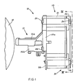
- the printing head is indicated by reference numeral 10 and comprises a front portion (nose) 11 which is intended to be directed towards a platen roller 12, an intermediate portion 13 and a rear portion 14.
- the front portion or nose 11 comprises a tubular housing 15 provided with a lower flange 15a and rear flanges 15b.
- the lower flange 15a is provided for fixing the head 10 to a carriage (not shown) which is arranged to be moved transversely in front of the roller 12 and the rear flange 15b connect the nose 11 to the intermediate portion 13.
- the nose 11 Fixed within the nose 11 are plurality of transverse walls 15c, 15d and 15e comprising guide holes which support a plurality of printing needles or wires 16.
- the needles 16 are finally guided adjacent to the roller 12 by a guide matrix 15f of hard material which is fixed to the front portion of the nose 11 in a manner known in the art.
- the nose 11 comprises an upper opening which is closed by a cover 11a fitted between the front portions of the nose and the rear flanges 15b thereof.
- the intermediate portion 13 of the head 10 includes within same a plurality of electromagnets or solenoids 17 comprising fixed cores 18 and movable armatures 19 operable to actuate the needles 16 for the printing operation.
- the cores 18 are mounted within a containment body 21 and the needles 16 can be displaced longitudinally by the movable armatures 19 for the printing operation.
- the nose 11 is fixed at the rear to the containment body 21 by means of screws 23.
- the rear portion 14 of the head 10 comprises a cover 24 which is fixed to the body 21 by means of screws 26, which provides for urging a part of the armatures 19 towards the cores 18, as will be described hereinafter.
- the cores 18 are formed by a pack of ferro-cobalt plates with two limbs 27 and 28 to define a generally U-shaped configuration.
- the containment body 21 is of a cup-shaped form and is defined by a tubular outside wall 29 and a front wall 31 and contains within same a tubular projection 32.
- the cores 18 (see Figures 4 and 6) are fixed by their limbs 27 to inward recesses 33 in the tubular wall 29 and form a ring within the wall 29.
- the limbs 27 are located in the peripheral portion of the head 10 and the limbs 28 are disposed adjacent to the projection 32.
- the cores 18 also define central planes 31 which pass through a longitudinal axis 36 of the head 10 and which are angularly spaced at a constant pitch.
- the head comprises twenty four needles 16 and the planes 34 of the cores 18 are thus spaced at 15°.
- each of the cores 18 Fixed on the inward limb 28 of each of the cores 18 are corresponding excitation coils 37.
- the assembly formed by the cores 18 and the coils 37 is encased in a potting mass of resin 38 (see Figure 2) which fills the space between the inward walls of the body 21 and the cores 18 with the respective coils 37 in the manner described in the present applicants' Italian patent application No 68141-A/87 filed on 29th December 1987 (EPA 88 830 566.1).
- leads of the coils 37 which are indicated at 39, pass through corresponding openings in the front wall 31 and are soldered to terminals of a closure plate 35 of plastics material, in a similar manner to the arrangement described in above-referenced patent application.
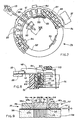
- the limbs 27 and 28 of the cores 18 are delimited by terminal surfaces 41 and 42 respectively which, after the cores are assembled to the body 21, are disposed in the same plane 43 which is perpendicular to the longitudinal axis 36.
- a thin separating disc 40 of kapton Interposed between the terminal surfaces 41 and 42 and the respective movable armatures 19 is a thin separating disc 40 of kapton, which performs an anti-adhesion function.
- the movable armatures 19 are formed by plates of ferro-magnetic material such as a ferro-cobalt alloy and each has a magnetic flux-closure surface 44 which faces towards the terminal surfaces 41 and 42 of the cores 18.
- the armatures 19 (see Figure 6) are of an elongate rectangular shape and have one end 45 with a step configuration 46.
- An opposite end 47 of each armature 19 is tapered and fixed by means of welding to a limb 48 formed by a thin steel plate perpendicular to the surface 44.
- the limb 48 Fixed by welding to one end 49 of the limb 48 is an end of a corresponding needle 16.
- the limb 48 is very light and is of such a shape as to be of a decreasing section from the region at which it is welded to the end 47, to the region in which it is welded to the needle 16.
- each movable armature 19 When the head 10 is in the assembled condition the movable armatures 19 (see Figure 4) are in a star-like configuration and each movable armature is disposed symmetrically with respect to the central plane 34 of the associated core 18.
- a ring 51 of resilient material for example silicone rubber, is accommodated in a recess 52 (see also Figure 3) in the cover 24 and acts on the armatures 19 in such a way as to cause the respective step configurations 46 to bear against the terminal surfaces 41 of the cores 18.
- a second ring 53 which is also of resilient material is accommodated in a recess 54 in the cover 24 in the vicinity of the ends 49 of the limbs 48.
- each of the limbs 48 is guided, on the same axis as the respective planes 34, by corresponding ribs 56 of a guide body 57.
- the guide body is of an annular shape, is made of low-friction plastics material and is engaged in a seat 32′ in the tubular projection 32 on the containment body 21. The angular position thereof is unambiguously defined with respect to the cores 18 by a key 55 engaged in a recess 55′ in the tubular projection 32.
- the guide body 57 has cylindrical spaces 58 in which return springs 59 are disposed.
- the springs 58 urge the respective limbs 48 towards the cover 24 until they come to bear against the ring 53.
- the surface 44 of the armature 19 and the terminal surface 42 of the limb 28 define the main air gap "G" of the solenoid 17.
- the rest position of the needles 16 and the air gap "G" depend on the thickness of the ring 53 and are precisely adjusted by a series of discs 60 of mylar which are disposed in the bottom of the recess 54 and the number of which defines the operating travel of the needles.
- the head 10 for each movable armature 19, the head 10 comprises a pair of projections 62 of ferro-magnetic material, for example pure iron, which are delimited by lateral surfaces 63a and 63b (see Figure 6) which are parallel to the central plane 34 of the respective core 18 and which are spaced from the surfaces 41 and 42.
- the projections 62 are interconnected by intermediate portions 64 and are produced, for example by cutting a plate, in the form of spokes of substantially triangular shape of a conducting disc 66 which is common to all the solenoids 17.
- the disc 66 comprises in particular an outer peripheral annular portion 65 which forms the intermediate portions 64 of the projections 62 and in which the projections 62 are directed towards the longitudinal axis 36, when the head 10 is in the assembled condition.
- the movable armatures 19 with their lateral edges as indicated at 67a and 67b are capable of moving between the lateral edges 63a and 63b of the projections or spokes 62.
- the surfaces 63a and 63b and the edges 67a and 67b represent the auxiliary air gaps "Ga” and "Gb” (see Figure 5) with respect to the main air gap "G”.
- the annular portion 65 is provided with holes 68 which are precisely connected to pins 70 which are fixed on the body 21.
- the disc 66 is of a thickness "Sd" which is comparable to the thickness "Sa” of the movable armatures 19.
- the ring 51 besides acting on the armatures 19, also provides for urging the disc 66 against an edge 71 of the wall 29 of the body 21 and the peripheral annular portion 65 is disposed in front of a part (about 30%) of the terminal surface 41 of the outward limbs 27 of the cores 18.
- each armature 19 comprises two lateral projections 72a and 72b which are engaged in two corresponding lateral openings 73a and 73b in the seats 69. That makes it possible to retain the movable armatures 19 and thus the needles 16 in a fixed radial position which is clearly defined with respect to the axis 36.
- the armatures 19 according to the invention are of a width "Wa” which is comparable to the width "Wc" of the surfaces 41 and 42 of the cores 18.
- the air gaps "Ga” and “Gb” reduce the reluctance of the magnetic circuit formed by the core 18 and the armature 19 and improve the level of magnetic efficiency. With the materials used, the energy transferred to the needles 16 and the travel movement of the needles being the same, the weight of the armatures 19 can therefore be reduced in comparison with the known arrangement of the state of the art, permitting an increase in the frequency of activation of the needles.
- the thickness "Sd” and Sa” are respectively 1.5 mm and 1.6 mm.
- the separation disc 40 is of a thickness of 0.03 mm and the air gap “G” is 0.15 to 0.20 mm.
- the limbs 48 are of a thickness of 0.30 mm and the needles are 0.25 mm in diameter.
- the armatures are wider than the surfaces 41 by about 40% in such a way that the distance between the surfaces 63a and 63b and the surfaces 41 and 42 is much greater than the air gaps "G", "Ga” and “Gb".
- the widths "Wc" and “Wa” are respectively 2.1 mm and 3 mm and the distance between the surfaces 63a and 63b of the spokes 62 is 3.3 mm, when the air gaps "Ga” and "Gb" are 0.15 mm.
- Figure 9 shows a highly efficient alternative construction in which "Wa” is 2.1 mm, equal to "Wc".
- the movable armatures and the associated spokes are as indicated at 76 and 77.
- the distance between the spokes is 2.4 mm.
- the lower parts of the spokes 77, corresponding to the corners, comprise recesses 78a and 78b which are 0.3 mm in depth and 0.3 mm in width and additional 45° bevels.
- the recesses 78a and 78b are disposed facing the lateral corners of the cores 18, corresponding to the surfaces 41 and 42, and prevent a component part of the magnetic flux at the core 18 being closed as between the limbs 27 and 28 without involving the movable armature 76.
- FIGS 7 and 8 shown an alternative embodiment of the guide body for the limbs 48, indicated herein at 86, comprising ribs 87 and recesses 88 with the same function as the ribs 56 and the recesses 58 in Figure 3.
- Each rib 87 has a shoulder 89 which partially closes off the subjacent recess 88 but permits guidance for the limb 48.
- the shoulders 89 retain the plungers 61 in the recesses 88 in the absence of any counteracting action on the part of the limbs 48 while however permitting upward movement of the limbs 48 until the limbs come to bear against the ring 53.
- the springs 59 and the plungers 61 are assembled to the guide body 86 in a preliminary operation to form a unitary return group as indicated at 91.
- the springs 59 and the plungers 61 are fitted into the recesses 88 through the lower part 90 of the guide body 86.
- the recesses 88 are then closed at their bottom by a retaining ring 92 which can be locked to the part 90 by means of resilient clips 93 engaged with corresponding teeth 94 on the guide body 86.
- the springs 59 are compressed and are retained in position by the ring 92 in such a way as to urge the plungers 61 against the shoulders 89 of the ribs 87.
- the guide body 86 is provided with a key 96 and the entire return group 91 is fixed in the seat 32′ of the tubular projection 32, the key 96 thereof engaging into the recess 55′, thereby to dispose the ribs 87 symmetrically at the sides of the central planes 43 of the cores 18.
Abstract
The needle printing head comprises a plurality of electromagnets having fixed cores (18), each with two limbs (27, 28) which are mounted in a ring within a containment body (21). Movable armatures (19) are disposed in a radiating array in front of coplanar terminal surfaces (41, 42) of the fixed cores (18). The movable armatures (19) each have a step configuration (46) for oscillating on the terminal surface (41) of the more outward limb (27), a surface (44) for closing the magnetic flux which, with the terminal surface (42) of the more inward limb (28) constitutes a main air gap, and an end (47) capable in printing of engaging a needle (16) by means of a corresponding connecting limb (48). In order to improve the level of magnetic efficiency, there is provided a magnetically conducting disc (66) of ferro-magnetic material and comprising a plurality of spokes (62) projecting radially inwardly from a peripheral annular portion (65) and disposed in juxtaposed alternating relationship with the movable armatures (19) so as to constitute auxiliary air gaps and for closure of the magnetic flux which is common to the armatures (19) and the cores (18).
Description
- The present invention relates to a needle printing head of the kind set forth in the pre-characterizing part of claim 1.
- Printing heads of the above-defined type are used generally in present-day needle printers. The main requirement of such heads is that of providing a high rate of printing with moderate powers of excitation of the electromagnets. To achieve that aim it is necessary for the movable parts to be light and for the air gap between cores and movable armatures to be very limited. That is in conflict with the need to have a level of printing energy sufficient for printing a plurality of copies and a relatively long travel movement on the part of the needles.
- One object of the present invention is therefore to provide a printing head having a high level of magnetic efficiency for reducing the dimensions of the movable parts and attaining high printing rates.
- A further object is to provide sufficiently high levels of printing energy and sufficiently long travel movements on the part of the needles.
- To this end the present invention provides a printing head as defined in claim 1.
- A further object of the invention is to provide a printing head which is of a very simple design configuration and in which the printing needles are guided and are returned to the rest condition in a highly reliable fashion.
- According to another aspect of the invention there is accordingly provided a printing head as defined in
claim 17. - The features of the invention will be apparent from the following description given by way of non-limiting example with reference to the accompanying drawings in which:
- Figure 1 is a side view of the printing head according to the invention,
- Figure 2 is a view in longitudinal section of the printing head in Figure 1,
- Figure 3 shows a view on an enlarged scale of some details from Figure 2,
- Figure 4 is a view of the printing head in section taken along line IV-IV in Figure 1,
- Figure 5 shows details from Figure 4 in section taken along line V-V,
- Figure 6 is a sectional perspective view of part of the head shown in Figure 1,
- Figure 7 is a partly sectional view of an alternative form of some details from Figure 4,
- Figure 8 is a view in section taken along line VIII-VIII in Figure 7, and
- Figure 9 is an alternative form of the details from Figure 5.
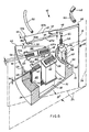
- Referring to Figures 1 and 2, the printing head is indicated by
reference numeral 10 and comprises a front portion (nose) 11 which is intended to be directed towards aplaten roller 12, anintermediate portion 13 and arear portion 14. - The front portion or
nose 11 comprises atubular housing 15 provided with alower flange 15a andrear flanges 15b. Thelower flange 15a is provided for fixing thehead 10 to a carriage (not shown) which is arranged to be moved transversely in front of theroller 12 and therear flange 15b connect thenose 11 to theintermediate portion 13. - Fixed within the
nose 11 are plurality oftransverse walls 15c, 15d and 15e comprising guide holes which support a plurality of printing needles orwires 16. Theneedles 16 are finally guided adjacent to theroller 12 by aguide matrix 15f of hard material which is fixed to the front portion of thenose 11 in a manner known in the art. Finally thenose 11 comprises an upper opening which is closed by acover 11a fitted between the front portions of the nose and therear flanges 15b thereof. - The
intermediate portion 13 of thehead 10 includes within same a plurality of electromagnets orsolenoids 17 comprisingfixed cores 18 andmovable armatures 19 operable to actuate theneedles 16 for the printing operation. Thecores 18 are mounted within acontainment body 21 and theneedles 16 can be displaced longitudinally by themovable armatures 19 for the printing operation. Thenose 11 is fixed at the rear to thecontainment body 21 by means ofscrews 23. - The
rear portion 14 of thehead 10 comprises acover 24 which is fixed to thebody 21 by means ofscrews 26, which provides for urging a part of thearmatures 19 towards thecores 18, as will be described hereinafter. - The
cores 18 are formed by a pack of ferro-cobalt plates with twolimbs containment body 21 is of a cup-shaped form and is defined by a tubularoutside wall 29 and afront wall 31 and contains within same atubular projection 32. The cores 18 (see Figures 4 and 6) are fixed by theirlimbs 27 toinward recesses 33 in thetubular wall 29 and form a ring within thewall 29. - The
limbs 27 are located in the peripheral portion of thehead 10 and thelimbs 28 are disposed adjacent to theprojection 32. Thecores 18 also definecentral planes 31 which pass through alongitudinal axis 36 of thehead 10 and which are angularly spaced at a constant pitch. In the embodiment described herein the head comprises twenty fourneedles 16 and theplanes 34 of thecores 18 are thus spaced at 15°. - Fixed on the
inward limb 28 of each of thecores 18 arecorresponding excitation coils 37. The assembly formed by thecores 18 and thecoils 37 is encased in a potting mass of resin 38 (see Figure 2) which fills the space between the inward walls of thebody 21 and thecores 18 with therespective coils 37 in the manner described in the present applicants' Italian patent application No 68141-A/87 filed on 29th December 1987 (EPA 88 830 566.1). - In particular the leads of the
coils 37, which are indicated at 39, pass through corresponding openings in thefront wall 31 and are soldered to terminals of aclosure plate 35 of plastics material, in a similar manner to the arrangement described in above-referenced patent application. - The
limbs terminal surfaces body 21, are disposed in the same plane 43 which is perpendicular to thelongitudinal axis 36. Interposed between theterminal surfaces movable armatures 19 is a thin separatingdisc 40 of kapton, which performs an anti-adhesion function. - The
movable armatures 19 are formed by plates of ferro-magnetic material such as a ferro-cobalt alloy and each has a magnetic flux-closure surface 44 which faces towards theterminal surfaces cores 18. The armatures 19 (see Figure 6) are of an elongate rectangular shape and have oneend 45 with astep configuration 46. Anopposite end 47 of eacharmature 19 is tapered and fixed by means of welding to alimb 48 formed by a thin steel plate perpendicular to thesurface 44. - Fixed by welding to one
end 49 of thelimb 48 is an end of acorresponding needle 16. Thelimb 48 is very light and is of such a shape as to be of a decreasing section from the region at which it is welded to theend 47, to the region in which it is welded to theneedle 16. - When the
head 10 is in the assembled condition the movable armatures 19 (see Figure 4) are in a star-like configuration and each movable armature is disposed symmetrically with respect to thecentral plane 34 of the associatedcore 18. Aring 51 of resilient material, for example silicone rubber, is accommodated in a recess 52 (see also Figure 3) in thecover 24 and acts on thearmatures 19 in such a way as to cause therespective step configurations 46 to bear against theterminal surfaces 41 of thecores 18. Asecond ring 53 which is also of resilient material is accommodated in arecess 54 in thecover 24 in the vicinity of theends 49 of thelimbs 48. - An intermediate portion of each of the
limbs 48 is guided, on the same axis as therespective planes 34, bycorresponding ribs 56 of aguide body 57. The guide body is of an annular shape, is made of low-friction plastics material and is engaged in aseat 32′ in thetubular projection 32 on thecontainment body 21. The angular position thereof is unambiguously defined with respect to thecores 18 by a key 55 engaged in arecess 55′ in thetubular projection 32. - Between the
ribs 56 theguide body 57 hascylindrical spaces 58 in whichreturn springs 59 are disposed. By means ofplungers 61 thesprings 58 urge therespective limbs 48 towards thecover 24 until they come to bear against thering 53. Thesurface 44 of thearmature 19 and theterminal surface 42 of thelimb 28 define the main air gap "G" of thesolenoid 17. The rest position of theneedles 16 and the air gap "G" depend on the thickness of thering 53 and are precisely adjusted by a series ofdiscs 60 of mylar which are disposed in the bottom of therecess 54 and the number of which defines the operating travel of the needles. - In accordance with the invention, for each
movable armature 19, thehead 10 comprises a pair ofprojections 62 of ferro-magnetic material, for example pure iron, which are delimited bylateral surfaces central plane 34 of therespective core 18 and which are spaced from thesurfaces projections 62 are interconnected byintermediate portions 64 and are produced, for example by cutting a plate, in the form of spokes of substantially triangular shape of a conductingdisc 66 which is common to all thesolenoids 17. Thedisc 66 comprises in particular an outer peripheralannular portion 65 which forms theintermediate portions 64 of theprojections 62 and in which theprojections 62 are directed towards thelongitudinal axis 36, when thehead 10 is in the assembled condition. - The
movable armatures 19 with their lateral edges as indicated at 67a and 67b are capable of moving between thelateral edges spokes 62. Thesurfaces edges surfaces planes 34, theannular portion 65 is provided withholes 68 which are precisely connected topins 70 which are fixed on thebody 21. - The
disc 66 is of a thickness "Sd" which is comparable to the thickness "Sa" of themovable armatures 19. When thehead 10 is in the assembled condition, thering 51, besides acting on thearmatures 19, also provides for urging thedisc 66 against anedge 71 of thewall 29 of thebody 21 and the peripheralannular portion 65 is disposed in front of a part (about 30%) of theterminal surface 41 of theoutward limbs 27 of thecores 18. - The
outward ends 45 of themovable armatures 19 are in turn accommodated incorresponding seats 69 in the peripheralannular portion 65 of thedisc 66. In additon theend 45 of eacharmature 19, adjacent to thestep configuration 46, comprises twolateral projections lateral openings seats 69. That makes it possible to retain themovable armatures 19 and thus theneedles 16 in a fixed radial position which is clearly defined with respect to theaxis 36. - In response to excitation of a coil 37 (see Figure 2) the corresponding
movable armature 19 oscillates at its step configuration (see Figures 4 and 5) and reduces the air gap "G", urging theneedle 16 in the printing direction. The magnetic flux generated by thecoil 37 and which is operable to move thearmature 19, besides being completed through the air gap "G", is also completed through the air gaps "Ga" and "Gb". - The
armatures 19 according to the invention are of a width "Wa" which is comparable to the width "Wc" of thesurfaces cores 18. The air gaps "Ga" and "Gb" reduce the reluctance of the magnetic circuit formed by thecore 18 and thearmature 19 and improve the level of magnetic efficiency. With the materials used, the energy transferred to theneedles 16 and the travel movement of the needles being the same, the weight of thearmatures 19 can therefore be reduced in comparison with the known arrangement of the state of the art, permitting an increase in the frequency of activation of the needles. - Preferably the thickness "Sd" and Sa" are respectively 1.5 mm and 1.6 mm. The
separation disc 40 is of a thickness of 0.03 mm and the air gap "G" is 0.15 to 0.20 mm. Thelimbs 48 are of a thickness of 0.30 mm and the needles are 0.25 mm in diameter. - In the embodiment shown in Figure 5 the armatures are wider than the
surfaces 41 by about 40% in such a way that the distance between thesurfaces surfaces surfaces spokes 62 is 3.3 mm, when the air gaps "Ga" and "Gb" are 0.15 mm. - Figure 9 shows a highly efficient alternative construction in which "Wa" is 2.1 mm, equal to "Wc". The movable armatures and the associated spokes are as indicated at 76 and 77. The distance between the spokes is 2.4 mm. The lower parts of the
spokes 77, corresponding to the corners, compriserecesses head 10 is in the assembled condition therecesses cores 18, corresponding to thesurfaces limbs movable armature 76. - With the embodiment described herein it is possible to achieve rates of oscillation of the needles of 2500 Hz for a working travel of 0.25-0.40 mm, such as to permit printing of at least two carbon copies.
- Figures 7 and 8 shown an alternative embodiment of the guide body for the
limbs 48, indicated herein at 86, comprisingribs 87 and recesses 88 with the same function as theribs 56 and therecesses 58 in Figure 3. Eachrib 87 has ashoulder 89 which partially closes off thesubjacent recess 88 but permits guidance for thelimb 48. Theshoulders 89 retain theplungers 61 in therecesses 88 in the absence of any counteracting action on the part of thelimbs 48 while however permitting upward movement of thelimbs 48 until the limbs come to bear against thering 53. - The
springs 59 and theplungers 61 are assembled to theguide body 86 in a preliminary operation to form a unitary return group as indicated at 91. In particular thesprings 59 and theplungers 61 are fitted into therecesses 88 through thelower part 90 of theguide body 86. Therecesses 88 are then closed at their bottom by a retainingring 92 which can be locked to thepart 90 by means ofresilient clips 93 engaged withcorresponding teeth 94 on theguide body 86. - The
springs 59 are compressed and are retained in position by thering 92 in such a way as to urge theplungers 61 against theshoulders 89 of theribs 87. Theguide body 86 is provided with a key 96 and theentire return group 91 is fixed in theseat 32′ of thetubular projection 32, the key 96 thereof engaging into therecess 55′, thereby to dispose theribs 87 symmetrically at the sides of the central planes 43 of thecores 18. - As will be apparent from Fig. 6 the
resilient ring 51 bears on thedisc 66 as well as thearmatures 19.
Claims (19)
1. A needle printing head comprising a plurality of needles (16) and a corresponding plurality of electromagnets (17), in which each electromagnet (17) comprises a fixed core (18) and a movable armature (19) and in which the fixed core has two terminal surfaces (41, 42) and can be excited to generate a magnetic flux through these surfaces and wherein the movable armature (19) is of a generally elongate shape and has a first oscillating end (47) for selectively acting on a corresponding needle (16) in a writing operation and a magnetic flux-closure surface (44)disposed facing a first surface (42) of said two terminal surfaces and in which the magnetic flux-closure surface (44), together with the first surface (42) of the core, form a main air gap (G) of the electromagnet, which gap is variable with the oscillating movement of the first end of the movable armature (19), characterized in that each electromagnet (17) has two ferro-magnetic concentration projections (62) delimited by the lateral edges (63a, b) which are adjacent to the terminal surfaces (41, 42) and the movable armature (19) moves between these lateral edges (63a, b) of the concentration projections (62) and these lateral edges form auxiliary air gaps (Ga, b) together with lateral edges (67a, b) of the movable armature (19) for closure of part of the magnetic flux through the concentration projections (62).
2. A head according to claim 1, characterized in that the movable armature (19), in the magnetic flux-closure zone, is of a greater width (Wc) than that (Wc) of the terminal surfaces (41, 42) by an amount such that the main air gap (G) and the auxiliary air gaps 9Ga, b) are negligible with respect to the distance between the fixed core (18) and the concentration projections (62).
3. A head according to claim 1, characterized in that the lateral edges (63a, b) of the concentration projections (62), in a region adjacent to the terminal surfaces (41, 42), have a shaped portion (78a, b), the distance of which from the fixed core (18) is much greater than the main air gap (G) and the auxiliary air gap (Ga, b).
4. A head according to claim 1, 2 or 3, characterized in that the movable armature (19) comprises a second end (45) which acts as a fulcrum on a second terminal surface (41) of the terminal surfaces (41, 42), and in which the concentration projections (62) are interconnected by a ferromagnetic intermediate portion (64) which is magnetically coupled to the second terminal surface (41) and to the second end (45) of the movable armature (19).
5. A head according to claim 2 or 3, characterized in that each movable armature (19) comprises a step configuration (46) at its second end (45), which defines an axis for fulcruming the movable armature on the second surface (41) of the fixed core (18).
6. A head according to any preceding claim, characterized in that the terminal surfaces (41, 42) of the cores (18) are coplanar with a common terminal plane and in which the concentration projections (42) are part of a plate member (66) of ferro-magnetic material parallel to the common terminal plane.
7. A head according to claim 6, characterized by a containment body (21) for the cores (18), a closure member (24) which is fixed to the containment body (21) and elastic engagement means (51) between the closure member (24) and the movable armatures (19).
8. A head according to claim 4, characterized by a containment body (21) for the cores (18), a closure member (24) which is fixed to the containment body (21), and elastically yielding means (51) between the closure member (24) and the movable armatures (19), wherein the terminal surface (41, 42) of the fixed cores (18) are coplanar with a common terminal plane, wherein the concentration projections (62) are disposed in the form of spokes of a magnetically conducting disc (66) of ferro-magnetic material parallel to this common terminal plane and wherein the elastically yielding means comprise a ring (51) of resilient material which acts between the closure member (24) on the one hand and the movable armatures (19) and the said disc (66) on the other hand.
9. A head according to claim 8, characterized in that each movable armature (19) comprises, adjacent the second end (45) thereof, a step configuration (46) which defines an axis for fulcruming of the armature on the second surface (41) of the fixed core (18), and wherein the elastically yielding means comprise a ring (51) of resilient material compressed between the closure member (24) and the movable armatures (19), in a region aligned with said the configuration (46).
10. A head according to any preceding claim, characterized in that the movable armatures (19) are disposed in a radiating arrangement and wherein the concentration projections (62) are located in alternate sectors with the armatures.
11. A head according to any preceding claim, characterized in that the fixed cores (18) are of a U-shaped section which is symmetrical with respect to the central plane thereof and the head further comprises a longitudinal geometrical axis (36), and wherein the terminal surfaces (41, 42) are disposed in a tranverse plane perpendicular to this axis (36), the fixed cores (18) are disposed around the axis in such a way that this axis (36) is coplanar with the central plane of each core (18) and the lateral edges (63a, b) of the concentration projections (62) are parallel to the longitudinal axis (36) and perpendicular to the said transverse plane.
12. A head according to any preceding claim, characterized in that concentration projections (62) each have a pair of stop surfaces and wherein each movable armature (19) comprises, on the lateral edges (67a, b) thereof and in opposite relationship to the first end (47), two pairs of cooperating surfaces engaged with the two pairs of stop surfaces of the concentration projections (62).
13. A head according to claim 12, characterized in that the cooperating surfaces and stop surfaces are defined by recesses (73a, b) and projections (72a, b) on movable armatures (19) and the concentration projections (62).
14. A head according to claim 9, characterized in that each movable armature (19) comprises two portions (72a, b) projecting from the sides of the second end (45) and the conducting disc (66) comprises a pair of recesses (73a, b) between each pair of spokes which form the concentration projections (62), wherein the projecting portions (72a, b) engage in the recesses (73a, b) to guide the movable armatures (19) during the oscillating movement thereof about the step configuration (46).
15. A head according to any preceding claim, characterized in that the fixed cores (18) are of a U-shaped section symmetrical with respect to a central plane thereof and the head further comprises a longitudinal geometrical axis (36), wherein the fixed cores are disposed around this longitudinal axis and in such a way that the longitudinal axis is coplanar with the central planes of the fixed cores (18), and wherein each movable armature (19) is held in the rest condition in a position of maximum distance of the air gap (G) by the action of a spring return element (59).
16. A head according to claim 15, characterized in that each needle (16) is welded to a corresponding actuating limb (48) formed by a tapered plate, wherein this plate (48) is welded with its portion of larger dimension to the first end (47) of the corresponding movable armature (19), in parallel relationship to the longitudinal axis (36), and wherein the return element (59) acts on the limb (48) in such a way as to cause the limb (48) to bear against a stop ring (55) of yielding material.
17. A needle printing head comprising a plurality of needles (16) and a corresponding plurality of electromagnets (17), wherein each electromagnet comprises a fixed core (18) with two terminal surfaces (41, 42) and which can be excited to generate a magnetic flux through these surfaces and a movable armature (19) of generally elongate shape, wherein each movable armature (19) has one end (45) fulcrumed on one of the two terminal surfaces (41) of the core (18), and wherein each movable armature (19) is normally held in a position of maximum distance of its air gap (G) formed between a surface (44) of the armature and the other terminal surface (42) of the fixed core (18) by the action of a corresponding spring return element (59), characterized in that each needle (16) is welded to a corresponding actuating limb (48) which in turn is is fixed to the second end (47) of the corresponding movable armature (19), each return element (59) acts on the limb (48) in such a way as to cause the limb to bear against a stop ring (53) of yielding material, and the actuating limbs (48) are guided by a unitary guide body (86) which accommodates the spring return elements (59) in a prestressed state, independently of their engagement with the limbs (48).
18. A head according to claim 17, characterized in that the spring return elements comprise coil springs (59) individually associated with the actuating limbs (49) and the unitary guide body (86) is provided with ribs (87). between which the actuating limbs (48) are guided, with recesses (88) accommodating the coil springs (59) in alignment with the limbs (48) and cooperating surfaces (89) on the ribs for retaining the coil springs (59) in the recesses (88) and permitting free movement of the limbs (48), and wherein a retaining ring (92) is attached to the guide body (86) to close the recesses (88) and act against the coil springs (59) to compress them against the cooperating surfaces (89) on the ribs (87) which retain the coil springs (59).
19. A head according to claim 17 or 18, characterized by a magnetically conducting disc (66) of ferro-magnetic material which is coupled to the fixed cores (18) of the electromagnets (17) and which is provided with spokes (62) adjacent to the terminal surfaces (41, 42), spokes (62) defining with the movable armatures (19) auxiliary air gaps (Ga, b) for reducing the magnetic reluctance of the assembly formed by the fixed cores (18) and movable armatures (19).
Applications Claiming Priority (2)
| Application Number | Priority Date | Filing Date | Title |
|---|---|---|---|
| IT6760488 | 1988-06-27 | ||
| IT67604/88A IT1219403B (en) | 1988-06-27 | 1988-06-27 | NEEDLE PRINT HEAD |
Publications (2)
| Publication Number | Publication Date |
|---|---|
| EP0349212A2 true EP0349212A2 (en) | 1990-01-03 |
| EP0349212A3 EP0349212A3 (en) | 1990-07-11 |
Family
ID=11303802
Family Applications (1)
| Application Number | Title | Priority Date | Filing Date |
|---|---|---|---|
| EP89306383A Ceased EP0349212A3 (en) | 1988-06-27 | 1989-06-23 | Needle printing head |
Country Status (4)
| Country | Link |
|---|---|
| US (1) | US5054942A (en) |
| EP (1) | EP0349212A3 (en) |
| JP (1) | JPH02111556A (en) |
| IT (1) | IT1219403B (en) |
Cited By (2)
| Publication number | Priority date | Publication date | Assignee | Title |
|---|---|---|---|---|
| GB2241924A (en) * | 1990-02-28 | 1991-09-18 | Citizen Watch Co Ltd | Dot matrix needle printheads |
| GB2250958A (en) * | 1990-12-21 | 1992-06-24 | Citizen Watch Co Ltd | Needle dot-matrix printhead construction |
Families Citing this family (8)
| Publication number | Priority date | Publication date | Assignee | Title |
|---|---|---|---|---|
| DE58908638D1 (en) * | 1989-09-18 | 1994-12-15 | Mannesmann Ag | Matrix needle print head. |
| IT1245468B (en) * | 1991-03-19 | 1994-09-20 | Microlys Spa | NEEDLE PRINT HEAD |
| US5310271A (en) * | 1991-04-30 | 1994-05-10 | Oki Electric Industry Co., Ltd. | Solenoid actuator |
| EP0622214B1 (en) * | 1993-04-28 | 1997-03-26 | COMPUPRINT S.p.A. | A wire printhead |
| US6607488B1 (en) * | 2000-03-02 | 2003-08-19 | Acuson Corporation | Medical diagnostic ultrasound system and method for scanning plane orientation |
| DE10152020C2 (en) * | 2001-03-20 | 2003-05-08 | Koenig & Bauer Ag | Device for adjusting the contact pressure of an adjustable roller |
| DE10113314C2 (en) * | 2001-03-20 | 2003-10-30 | Koenig & Bauer Ag | fixing |
| WO2003049947A2 (en) * | 2001-12-06 | 2003-06-19 | Koenig & Bauer Aktiengesellschaft | Method and devices for regulating at least one cylinder in a printing machine and/or placing/removing said cylinders |
Citations (3)
| Publication number | Priority date | Publication date | Assignee | Title |
|---|---|---|---|---|
| US4569605A (en) * | 1984-02-02 | 1986-02-11 | International Business Machines Corporation | Wire driving armature for dot printer |
| GB2175853A (en) * | 1985-05-23 | 1986-12-10 | Seikosha Kk | Print head hammer mechanism |
| JPS6364766A (en) * | 1986-09-06 | 1988-03-23 | Brother Ind Ltd | Printing head |
Family Cites Families (8)
| Publication number | Priority date | Publication date | Assignee | Title |
|---|---|---|---|---|
| JPS53133117A (en) * | 1977-04-22 | 1978-11-20 | Seikosha Kk | Wire printer |
| US4423969A (en) * | 1982-01-06 | 1984-01-03 | Precision Handling Devices, Inc. | Print head |
| JPS60124262A (en) * | 1983-12-09 | 1985-07-03 | Tokyo Electric Co Ltd | Wire dot printer |
| JPS6122962A (en) * | 1984-07-10 | 1986-01-31 | Matsushita Electric Works Ltd | Dot printer head |
| US4767227A (en) * | 1985-01-25 | 1988-08-30 | Seiko Epson Corporation | Print wire driving device for wire type dot printer |
| JPS62148273A (en) * | 1985-12-23 | 1987-07-02 | Seiko Epson Corp | Printing head |
| US4944615A (en) * | 1986-04-07 | 1990-07-31 | Brother Kogyo Kabushiki Kaisha | Permanent magnet print head assembly with a square magnet |
| JPS6323041U (en) * | 1986-07-28 | 1988-02-16 |
-
1988
- 1988-06-27 IT IT67604/88A patent/IT1219403B/en active
-
1989
- 1989-06-23 EP EP89306383A patent/EP0349212A3/en not_active Ceased
- 1989-06-26 US US07/371,280 patent/US5054942A/en not_active Expired - Lifetime
- 1989-06-27 JP JP1165128A patent/JPH02111556A/en active Pending
Patent Citations (3)
| Publication number | Priority date | Publication date | Assignee | Title |
|---|---|---|---|---|
| US4569605A (en) * | 1984-02-02 | 1986-02-11 | International Business Machines Corporation | Wire driving armature for dot printer |
| GB2175853A (en) * | 1985-05-23 | 1986-12-10 | Seikosha Kk | Print head hammer mechanism |
| JPS6364766A (en) * | 1986-09-06 | 1988-03-23 | Brother Ind Ltd | Printing head |
Non-Patent Citations (1)
| Title |
|---|
| PATENT ABSTRACTS OF JAPAN vol. 12, no. 289 (M-728)(3136) 08 August 1988, & JP-A-63 64766 (BROTHER IND LTD) 23 March 1988, * |
Cited By (4)
| Publication number | Priority date | Publication date | Assignee | Title |
|---|---|---|---|---|
| GB2241924A (en) * | 1990-02-28 | 1991-09-18 | Citizen Watch Co Ltd | Dot matrix needle printheads |
| GB2241924B (en) * | 1990-02-28 | 1994-04-27 | Citizen Watch Co Ltd | Print head for a dot matrix printer |
| GB2250958A (en) * | 1990-12-21 | 1992-06-24 | Citizen Watch Co Ltd | Needle dot-matrix printhead construction |
| GB2250958B (en) * | 1990-12-21 | 1995-03-08 | Citizen Watch Co Ltd | Printing head for printer |
Also Published As
| Publication number | Publication date |
|---|---|
| IT8867604A0 (en) | 1988-06-27 |
| IT1219403B (en) | 1990-05-11 |
| US5054942A (en) | 1991-10-08 |
| JPH02111556A (en) | 1990-04-24 |
| EP0349212A3 (en) | 1990-07-11 |
Similar Documents
| Publication | Publication Date | Title |
|---|---|---|
| US4537520A (en) | Dot printer head with reduced magnetic interference | |
| EP0349212A2 (en) | Needle printing head | |
| CA1083414A (en) | Matrix print head and solenoid driver | |
| US4165940A (en) | Free flight head assembly for dot matrix printers and the like | |
| US4947146A (en) | Electromagnetic contactor | |
| US4344103A (en) | Electromagnetic relay | |
| US6731191B2 (en) | DC electromagnet | |
| EP0418268B1 (en) | Dot matrix print head assembly | |
| CA1249625A (en) | Electromagnetic actuator mechanism in particular for print hammer drives | |
| EP0117145B1 (en) | Dot impact printing head | |
| GB2074381A (en) | Electromagnetic relay | |
| EP0175763B1 (en) | High-speed wire print head with wire print position shift apparatus | |
| JPS59194870A (en) | Spring energy accumulating type dot printing head | |
| EP0411148A1 (en) | Wire dot printing head | |
| US4484519A (en) | Stylus driving apparatus for printers | |
| US4950092A (en) | Wire dot print head with a pair of guide nose halves | |
| KR930004840B1 (en) | Dot printer head | |
| JPS6140165A (en) | Printing head | |
| JPH0237559Y2 (en) | ||
| EP0305137A2 (en) | Wire-dot printing head | |
| JPH0339250Y2 (en) | ||
| EP0480032A1 (en) | Wire dot printing head | |
| JPH02137934A (en) | Dot printer head | |
| JPH0443329Y2 (en) | ||
| JPH0716438Y2 (en) | Wire dot print head |
Legal Events
| Date | Code | Title | Description |
|---|---|---|---|
| PUAI | Public reference made under article 153(3) epc to a published international application that has entered the european phase |
Free format text: ORIGINAL CODE: 0009012 |
|
| AK | Designated contracting states |
Kind code of ref document: A2 Designated state(s): DE FR GB |
|
| PUAL | Search report despatched |
Free format text: ORIGINAL CODE: 0009013 |
|
| AK | Designated contracting states |
Kind code of ref document: A3 Designated state(s): DE FR GB |
|
| 17P | Request for examination filed |
Effective date: 19901220 |
|
| 17Q | First examination report despatched |
Effective date: 19920806 |
|
| STAA | Information on the status of an ep patent application or granted ep patent |
Free format text: STATUS: THE APPLICATION HAS BEEN REFUSED |
|
| 18R | Application refused |
Effective date: 19940321 |