EP0349177A2 - Method of installing painting system and painting machine control unit for use in a painting booth - Google Patents
Method of installing painting system and painting machine control unit for use in a painting booth Download PDFInfo
- Publication number
- EP0349177A2 EP0349177A2 EP89306194A EP89306194A EP0349177A2 EP 0349177 A2 EP0349177 A2 EP 0349177A2 EP 89306194 A EP89306194 A EP 89306194A EP 89306194 A EP89306194 A EP 89306194A EP 0349177 A2 EP0349177 A2 EP 0349177A2
- Authority
- EP
- European Patent Office
- Prior art keywords
- painting
- control unit
- machine
- wall portion
- booth
- Prior art date
- Legal status (The legal status is an assumption and is not a legal conclusion. Google has not performed a legal analysis and makes no representation as to the accuracy of the status listed.)
- Granted
Links
Images



Classifications
-
- B—PERFORMING OPERATIONS; TRANSPORTING
- B05—SPRAYING OR ATOMISING IN GENERAL; APPLYING FLUENT MATERIALS TO SURFACES, IN GENERAL
- B05B—SPRAYING APPARATUS; ATOMISING APPARATUS; NOZZLES
- B05B16/00—Spray booths
- B05B16/40—Construction elements specially adapted therefor, e.g. floors, walls or ceilings
-
- B—PERFORMING OPERATIONS; TRANSPORTING
- B05—SPRAYING OR ATOMISING IN GENERAL; APPLYING FLUENT MATERIALS TO SURFACES, IN GENERAL
- B05B—SPRAYING APPARATUS; ATOMISING APPARATUS; NOZZLES
- B05B16/00—Spray booths
- B05B16/90—Spray booths comprising conveying means for moving objects or other work to be sprayed in and out of the booth, e.g. through the booth
- B05B16/95—Spray booths comprising conveying means for moving objects or other work to be sprayed in and out of the booth, e.g. through the booth the objects or other work to be sprayed lying on, or being held above the conveying means, i.e. not hanging from the conveying means
-
- B—PERFORMING OPERATIONS; TRANSPORTING
- B05—SPRAYING OR ATOMISING IN GENERAL; APPLYING FLUENT MATERIALS TO SURFACES, IN GENERAL
- B05B—SPRAYING APPARATUS; ATOMISING APPARATUS; NOZZLES
- B05B13/00—Machines or plants for applying liquids or other fluent materials to surfaces of objects or other work by spraying, not covered by groups B05B1/00 - B05B11/00
- B05B13/02—Means for supporting work; Arrangement or mounting of spray heads; Adaptation or arrangement of means for feeding work
- B05B13/04—Means for supporting work; Arrangement or mounting of spray heads; Adaptation or arrangement of means for feeding work the spray heads being moved during spraying operation
- B05B13/0431—Means for supporting work; Arrangement or mounting of spray heads; Adaptation or arrangement of means for feeding work the spray heads being moved during spraying operation with spray heads moved by robots or articulated arms, e.g. for applying liquid or other fluent material to three-dimensional [3D] surfaces
- B05B13/0433—Means for supporting work; Arrangement or mounting of spray heads; Adaptation or arrangement of means for feeding work the spray heads being moved during spraying operation with spray heads moved by robots or articulated arms, e.g. for applying liquid or other fluent material to three-dimensional [3D] surfaces the work being vehicle components, e.g. vehicle bodies
-
- B—PERFORMING OPERATIONS; TRANSPORTING
- B05—SPRAYING OR ATOMISING IN GENERAL; APPLYING FLUENT MATERIALS TO SURFACES, IN GENERAL
- B05B—SPRAYING APPARATUS; ATOMISING APPARATUS; NOZZLES
- B05B13/00—Machines or plants for applying liquids or other fluent materials to surfaces of objects or other work by spraying, not covered by groups B05B1/00 - B05B11/00
- B05B13/02—Means for supporting work; Arrangement or mounting of spray heads; Adaptation or arrangement of means for feeding work
- B05B13/04—Means for supporting work; Arrangement or mounting of spray heads; Adaptation or arrangement of means for feeding work the spray heads being moved during spraying operation
- B05B13/0447—Installation or apparatus for applying liquid or other fluent material to conveyed separate articles
- B05B13/0452—Installation or apparatus for applying liquid or other fluent material to conveyed separate articles the objects being vehicle components, e.g. vehicle bodies
-
- Y—GENERAL TAGGING OF NEW TECHNOLOGICAL DEVELOPMENTS; GENERAL TAGGING OF CROSS-SECTIONAL TECHNOLOGIES SPANNING OVER SEVERAL SECTIONS OF THE IPC; TECHNICAL SUBJECTS COVERED BY FORMER USPC CROSS-REFERENCE ART COLLECTIONS [XRACs] AND DIGESTS
- Y10—TECHNICAL SUBJECTS COVERED BY FORMER USPC
- Y10S—TECHNICAL SUBJECTS COVERED BY FORMER USPC CROSS-REFERENCE ART COLLECTIONS [XRACs] AND DIGESTS
- Y10S118/00—Coating apparatus
- Y10S118/07—Hoods
-
- Y—GENERAL TAGGING OF NEW TECHNOLOGICAL DEVELOPMENTS; GENERAL TAGGING OF CROSS-SECTIONAL TECHNOLOGIES SPANNING OVER SEVERAL SECTIONS OF THE IPC; TECHNICAL SUBJECTS COVERED BY FORMER USPC CROSS-REFERENCE ART COLLECTIONS [XRACs] AND DIGESTS
- Y10—TECHNICAL SUBJECTS COVERED BY FORMER USPC
- Y10S—TECHNICAL SUBJECTS COVERED BY FORMER USPC CROSS-REFERENCE ART COLLECTIONS [XRACs] AND DIGESTS
- Y10S55/00—Gas separation
- Y10S55/46—Spray booths
Definitions
- the present invention relates to a method of installing painting sytem and a painting-machine control unit for use in a painting booth.
- a control unit C is defined herein as one or a combination of an operation control panel, electric control panel, air-pressure control panel, an electrostatic painting high-voltage generator and so on.
- An external device is defined herein as one or combination of a power source, a paint feed device, a compressed air feed device and so on.
- a first operation coupler is defined herein as one or combined plurality of a paint transport pipe, an electric cable, a compressed air pipe, an optical fiber and so on for communicating objects or data between the control unit C or the external device and a painting machine 13.
- a second operation coupler is defined herein as one or combination of a paint transport pipe, an electric cable, a compressed air pipe, an optical fiber and so on for communicating objects or data between a sub-unit relating to the operation control panel, a sub-unit relating to the electric control panel, a sub-unit relating to the air-pressure control panel and a sub-unit relating to the electrostatic painting high-voltage generator.
- Fig. 9 which shows a prior art method
- a painting machine 13 which has been assembled at another factory is introduced and installed on the floor of the painting booth 1, and also a control unit C for controlling the painting machine 13 is installed externally of the booth 1.
- the following operations are carried out through a side wall of the painting booth 1 for operatively connecting the painting machine 13 and the control unit C opposed to each other across the booth side wall.
- the primary object of the present invention is to provide an improved method of installing a painting system at a painting booth which method can significantly reduce the time required for the system to become ready for actual painting operation after its initial installment at the booth.
- a second object of the present invention is to provide an improved painting apparatus which permits easy and quick pre-operation testing procedures.
- a method of the invention for installing a painting system in a painting booth comprises the steps of:
- the painting-machine control unit pre-connected at least with the control unit is shipped and then assembled with the painting booth. Accordingly, the assembly and connection operations including those of the control unit C may be carried out speedily at the painting factory. Then, the control unit is connected also with the first operation coupler when the unit is shipped at step (e), the connecting operations of the first operation coupler which includes various pipes and the like need not be carried out at the painting factory. Also, even if the control unit is shipped without being pre-connected with the first operation coupler, since the checking operations of proper connections are already carried out at the manufacturing factory, connecting and wire-extending operations between the painting machine and the control unit may be carried out without errors and speedily.
- the time required for adjustments and checks effected at a test run after pipe and cable extending operations may be significantly reduced or even eliminated at all.
- said painting machine is attached further to said wall portion.
- the installment operations at the painting site of the painting machine and the control unit may be further facilitated since the same are completed with only attaching the painting-machine control unit including the same to the side wall of the painting booth. With such further reduced time for installing the unit, other subsequent installment operations of the air conditioning device and the conveyor line of the painting booth will be carried out smoothly.
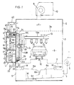
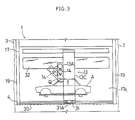
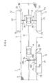
- FIG. 1 through 4 illustrate one preferred embodiment of the present invention.
- a painting booth 1 includes a ceiling 2, a side wall 3 and a floor 4 for forming together with a tunnel-shaped painting work area 5.
- the ceiling defines over substantially entire face thereof an air discharge opening with a filter 2a for discharging a ventilation air downwardly therethrough.
- the floor 4 has its substantially entire face formed of a grating member as an air exhaust opening for exhausting the air at the work area together with excess sprayed paint mist.
- Numeral 6 denotes a cleaing device for trapping and eliminating the excess paint mist from the air exhausted through the floor 4. This paint-eliminated air is exhausted externally of the booth via an exhaust air passage 7 and an air exhaust fan 8.
- numeral 9 denotes an air feed fan for feeding the ventilation air conditioned by an air conditioner 10 to a ceiling air feed chamber 11.
- a conveyor 12 for conveying a paint-target object (a body of an automobile in this embodiment) inside the booth. Then, the paint-target object undergoes an automatic spray painting operation by means of an automatic painting machine 13 to be described next, while being conveyed on the conveyor 12.
- the painting-machine control unit 10 includes a box type housing 17 having a separate wall portion 17a for forming the side wall 3, the painting machine 13 and a control unit C having an operation control panel 18 for operating the painting machine 13.
- the automatic painting machine 13 effects a spray painting operation by means of a pair of electrostatic spray guns 14 thereof.
- These spray guns 14 are attached to a first movable portion 13A formed as a letter 'L'-shaped arm, whereas a second movable portion 13B supports the first movable portion 13A such that the portion 13A may move along the transverse direction of the booth and also pivot about an axis Q positioned at the leading ends of the spray guns 14.
- the second movable portion 13B is supported on a base portion 13C to be vertically liftable relative thereto.
- This base portion 13C is movable in the object conveying direction relative to the painting booth 1 and is formed continuously with a housing 17 so as to move along a wall portion 17a as being suspended from the same.
- an engaging portion 31 equipped with a roller 31a for preventing vibrations of the base portion 13C through its engagement with a guide rail 30. Since the wall portion 17a is formed as an integral part of the box type housing 17, this wall portion 17a is physically reinforced for more reliably supporting the painting machine 13.
- Numeral 24 denotes a first operation coupler including electric cables, paint pipes, compressed air pipes or the like in e.g. a bundled state for operative connections between the housing 17 and the automatic painting machine 13.
- This first operation coupler 24 is accommodated in a crawler type mechanism 25 so as to permit the movement of the base portion 13C of the automatic painting machine.
- Similar mechanisms 26 and 27 are provided also to the second movable portion 13B accommodating a move-drive mechanism 28 for the first movable portion 13A and to the base portion 13C accommodating a lift-drive mechanism 29 for the second movable portion 13B.
- the automatic spraying machine 13 effects an automatic spray painting operation on the conveyed target object A while the horizontally-oriented axis Q being positioned over the target surface of the object A and maintaining the spray guns 14 at a predetermined distance from the object surface. Further, with a pivotal drive of the first movable portion 13A, the spray guns 14 are pivoted about the axis Q to have their spraying directions positioned normal to the object surface, whereby the spraying areas of the guns 14 may cover the entire width of the target object A. With these operations, as the object A is conveyed on the conveyor 12, the object has its front, upper and rear faces automatically spray-painted.
- the interior of the housing 17 is divided into upper, middle and lower sections.
- An operator's chamber 16 disposed in the middle section accommodates an operation control panel 18 and a high-voltage generator 23 for the electrostatic painting operation.
- a wall portion 17a in the middle section of the housing 17 includes a monitor window formed of a transparent plate such as of polypropylene for monitoring the inside of the booth.
- the upper housing section includes a move-drive mechanism 20 for moving the base portion 13C of the painting machine 13 along the wall portion 17a of the housing 17 (i.e. the object-conveying direction in the booth).
- the lower housing section accommodates an electric control panel 21 for the painting machine 13, an air pressure control panel 22 for the spray guns 14, and so on.
- a ceiling frame 16a and a floor frame 16b of the operator's chamber 16 inside the housing 17 respectively define air feed openings 41, such that a portion of the ventilation air is introduced from a duct 40 communicating with the ceiling air feed chamber 11 into the operator's chamber 16 through the air feed opening of the ceiling frame 16a and is exhausted therefrom through an air exhaust grating 42 defined in a back face of this housing 17.
- a dumper 43 disposed inside the duct 40 adjusts the amount of ventilation air from the ceiling air feed chamber 11 so as to increase the atmospheric pressure inside the housing 17, thereby effectively separating an operator and the control unit C inside the chamber 16 from the atmosphere containing excess paint mist and solution gas.
- this wall portion 17a and casings for the respective portions 13A, 13B and 13C of the painting machine 13 are formed by affixing polypropylene plate elements to skeltons, thereby to prevent or restrict adhesive accumulation of the excess paint mist charged through the electrostatic painting to these wall portions and casings.
- the housing 17 is assembled, in which the monitor window 32, the duct 40 and connecting elements for the side wall 3 of the painting booth 1 are also attached to the housing 17.
- the control unit C is installed at the wall portion 17a of the housing 17, the floor frame 16a of the housing 17 and the floor of the housing 17 to form the floor of the painting booth. More specifically, the operation control panel 18 for the painting machine 13 is incorporated in the operator's chamber 16, and the base-portion move-drive mechanism 20, electric control panel 21, air pressure control panel 22, the high-voltage generator 23 and so on are incorporated into the housing, thereby assemblying the painting-machine control unit U.
- the base portion 13C of the painting machine 13 is attached, thereby attaching the unit U to the machine 13.
- the various control devices are interconnected via a second operation coupler and the first operation coupler such as the electric cables, paint pipes, compressed air pipes and so on to be extended between the housing 17 and the painting machine 13 are aso interconnected, thereby setting the control unit U ready for operations of the painting machine 13.
- the test operations of the control unit C, first and second operation couplers and the painting machine 13 are carried out and also checks and adjustments, if necessary, of the painting machine 13 are carried out before the shipment of the unit U.
- the operator may readily assess the test operation conditions of the painting machine 13 through the monitor window 32.
- This painting-machine control unit U having its operations checked and adjusted is shipped as it is pre-assembled with the machine 13 from the factory to the installation site of the painting booth 1 to be assembled with the same.
- the first operation coupler 24 such as the paint transport pipes extending from the machine 13 is disposed through the wall portion 17a. Accordingly, if the unit U is shipped to the booth installed site with being attached with the first operation coupler 24, the wall portion 17a protects this first operation coupler 24 from damage in the course of the shipment.
- the wall portion 17a of the housing 17 is engaged into the connecting opening 3a defined in the side wall 3 of the painting booth 1, and a connecting portion provided at a peripheral edge of the opening 3a of the booth 1 and the connecting elements provided at the wall portion 17a of the unit U are fixedly connected with each other by means of such connecting means as welding and bolts.
- the operator's chamber 16 incorporating the control panel 18 and the automatic painting machine 13 may be assembled at one time.
- the wall portion 17a of the unit U may be advantageously reinforced by the box type housing 17.
- reinforcing pole members 19 at the opposed sides of the connecting opening 3a.
- An extention coupler member 33 comprises cables and pipes such as electric cables, compressed air pipes for connecting the external devices with the housing 17.
- automatic side spraying machines 15 for spraying paint on the sides of the object A are disposed at the opposed sides of the painting booth 1 at the upstream and downstream of the object-conveying direction. And, these side spraying machines 15 are installed to the booth 1 through the same unit construction as that of the machine 15.
Landscapes
- Details Or Accessories Of Spraying Plant Or Apparatus (AREA)
- Spray Control Apparatus (AREA)
- Automobile Manufacture Line, Endless Track Vehicle, Trailer (AREA)
- Coating Apparatus (AREA)
- Application Of Or Painting With Fluid Materials (AREA)
Abstract
Description
- The present invention relates to a method of installing painting sytem and a painting-machine control unit for use in a painting booth.
- First, before describing the invention, terms employed in this specification will be specifically defined.
- A control unit C is defined herein as one or a combination of an operation control panel, electric control panel, air-pressure control panel, an electrostatic painting high-voltage generator and so on.
- An external device is defined herein as one or combination of a power source, a paint feed device, a compressed air feed device and so on.
- A first operation coupler is defined herein as one or combined plurality of a paint transport pipe, an electric cable, a compressed air pipe, an optical fiber and so on for communicating objects or data between the control unit C or the external device and a
painting machine 13. - Further, when the control unit C consists of a combination of a plurality of the above-listed devices, a second operation coupler is defined herein as one or combination of a paint transport pipe, an electric cable, a compressed air pipe, an optical fiber and so on for communicating objects or data between a sub-unit relating to the operation control panel, a sub-unit relating to the electric control panel, a sub-unit relating to the air-pressure control panel and a sub-unit relating to the electrostatic painting high-voltage generator.
- Conventionally, as illustrated in Fig. 9 which shows a prior art method, after completion of a
painting booth 1 at the painting factory, apainting machine 13 which has been assembled at another factory is introduced and installed on the floor of thepainting booth 1, and also a control unit C for controlling thepainting machine 13 is installed externally of thebooth 1. After the initial installments, the following operations are carried out through a side wall of thepainting booth 1 for operatively connecting thepainting machine 13 and the control unit C opposed to each other across the booth side wall. - (I) connecting via various control valves varied and many pipes such as color paint transport pipes of various colors from the externally installed device through the side wall of the painting booth to the painting machine inside the booth;
- (II) connecting compressed pressure air pipes for opening/closing the valves and couplers for communicating various control signals respectively to the painting machine between the control unit C and the
painting machine 13 through the side wall; - Moreover, the following checking and/or adjusting operations are carried out to check the proper connections and installments.
- (III) checking the proper connection between the
painting machine 13 and the control unit C; - (VI) checking whether the various paint transport pipes have been properly connected with the respective pipe-connecting positions of the painting machine through the side wall of the
booth 1. - (V) checking whether the control unit C disposed externally of the
booth 1 can properly operate thepainting machine 13 and the control valves. - With the above-specified prior installing method; however, after the initial installments of the painting machine and the control unit, the operations (I) and (II) for the connections and installations through the side wall take a great amount of time. Further, the checking/adjusting operations (III) through (V) are also time-consuming and troublesome. Namely, the cables and pipes relating to the control unit C are great in number and complicated, thereby making the above operations further difficult. Accordingly, it is not rare that the system becomes ready for painting operation only after no less than one or two months counted from the date of the initial installments of the
painting machine 13 and the control unit C. - In view of the above problem, the primary object of the present invention is to provide an improved method of installing a painting system at a painting booth which method can significantly reduce the time required for the system to become ready for actual painting operation after its initial installment at the booth.
- A second object of the present invention is to provide an improved painting apparatus which permits easy and quick pre-operation testing procedures.
- In order to accomplish the above-described primary object, a method of the invention for installing a painting system in a painting booth comprises the steps of:
- (a) manufacturing a wall portion to be used in a side wall of the painting booth disposed adjacent a painting machine in the painting booth, the manufacturing step being effected separately from the manufacturing step of the side wall;
- (b) attaching a control unit for controlling the painting machine to one side of the wall portion corresponding to an outer face of the painting booth and assembling a painting-machine control unit including the control unit and the wall portion;
- (c) attaching the painting machine to another side of the wall portion opposed to the side attached with the control unit;
- (d) operatively connecting the control unit with the painting machine by means of a first operation coupler and effecting test operations of the control unit, the first operation and the painting machine; and
- (e) after effecting the steps (a) through (d) at a site different from a painting booth installment site, shipping at least the painting-machine control unit connected with or disconnected from the first operation coupler to said site and assembling the same with a portion of the side wall of the painting booth.
- With the first characterizing feature of the invention, at step (e), the painting-machine control unit pre-connected at least with the control unit is shipped and then assembled with the painting booth. Accordingly, the assembly and connection operations including those of the control unit C may be carried out speedily at the painting factory. Then, the control unit is connected also with the first operation coupler when the unit is shipped at step (e), the connecting operations of the first operation coupler which includes various pipes and the like need not be carried out at the painting factory. Also, even if the control unit is shipped without being pre-connected with the first operation coupler, since the checking operations of proper connections are already carried out at the manufacturing factory, connecting and wire-extending operations between the painting machine and the control unit may be carried out without errors and speedily.
- Further, as at the step (d) the test operations are carried out with complete connections before the shipment, the time required for adjustments and checks effected at a test run after pipe and cable extending operations may be significantly reduced or even eliminated at all.
- Further, according to a second characterizing feature of the present invention, preferably, in said painting-machine control unit shipped at the step (e), said painting machine is attached further to said wall portion.
- With this second feature, the installment operations at the painting site of the painting machine and the control unit may be further facilitated since the same are completed with only attaching the painting-machine control unit including the same to the side wall of the painting booth. With such further reduced time for installing the unit, other subsequent installment operations of the air conditioning device and the conveyor line of the painting booth will be carried out smoothly.
- According to a third characterizing feature of the invention, at the shipping step (e), all or a part of the painting machine is kept disconnected from the control unit.
- With this third feature, it becomes possible to reduce the total weight and volume of the painting-machine control unit to be shipped and also effectively to protect the driving unit of the painting machine from damages during the shipment, thereby furher facilitating the speedy shipment of the painting-machine control unit.
- The foregoing and other objects, features and advantages of the invention will be apparent from the following more particular description of preferred embodiment of the invention, as illustrated in the accompanying drawings.
- Accompanying drawings Figs. 1 through 4 illustrate one preferred embodiment of the present invention; in which,
- Fig. 1 is a section view,
- Fig. 2 is a perspective view,
- Fig. 3 is a side view, and
- Fig. 4 is a plane view
- Figs. 5 through 8 are section views and perspective views showing alternate embodiments; and
- Fig. 9 is a section view showing the prior art.
- Preferred embodiments of the present invention will be particularly described hereinafter with reference to the accompanying drawings.
- First, constructions of a painting booth and a painting-machine control unit will be described with reference to Figs. 1 through 4.
- A
painting booth 1 includes aceiling 2, aside wall 3 and afloor 4 for forming together with a tunnel-shapedpainting work area 5. The ceiling defines over substantially entire face thereof an air discharge opening with afilter 2a for discharging a ventilation air downwardly therethrough. Thefloor 4 has its substantially entire face formed of a grating member as an air exhaust opening for exhausting the air at the work area together with excess sprayed paint mist. Numeral 6 denotes a cleaing device for trapping and eliminating the excess paint mist from the air exhausted through thefloor 4. This paint-eliminated air is exhausted externally of the booth via an exhaust air passage 7 and an air exhaust fan 8. On the other hand,numeral 9 denotes an air feed fan for feeding the ventilation air conditioned by anair conditioner 10 to a ceilingair feed chamber 11. On thefloor 4, there is provided aconveyor 12 for conveying a paint-target object (a body of an automobile in this embodiment) inside the booth. Then, the paint-target object undergoes an automatic spray painting operation by means of anautomatic painting machine 13 to be described next, while being conveyed on theconveyor 12. - The painting-
machine control unit 10 includes abox type housing 17 having aseparate wall portion 17a for forming theside wall 3, thepainting machine 13 and a control unit C having anoperation control panel 18 for operating thepainting machine 13. - The
automatic painting machine 13 effects a spray painting operation by means of a pair ofelectrostatic spray guns 14 thereof. Thesespray guns 14 are attached to a firstmovable portion 13A formed as a letter 'L'-shaped arm, whereas a secondmovable portion 13B supports the firstmovable portion 13A such that theportion 13A may move along the transverse direction of the booth and also pivot about an axis Q positioned at the leading ends of thespray guns 14. Further, the secondmovable portion 13B is supported on abase portion 13C to be vertically liftable relative thereto. Thisbase portion 13C is movable in the object conveying direction relative to thepainting booth 1 and is formed continuously with ahousing 17 so as to move along awall portion 17a as being suspended from the same. At a lower end of thebase portion 13C, there is provided an engagingportion 31 equipped with aroller 31a for preventing vibrations of thebase portion 13C through its engagement with aguide rail 30. Since thewall portion 17a is formed as an integral part of thebox type housing 17, thiswall portion 17a is physically reinforced for more reliably supporting thepainting machine 13. -
Numeral 24 denotes a first operation coupler including electric cables, paint pipes, compressed air pipes or the like in e.g. a bundled state for operative connections between thehousing 17 and theautomatic painting machine 13. Thisfirst operation coupler 24 is accommodated in acrawler type mechanism 25 so as to permit the movement of thebase portion 13C of the automatic painting machine.Similar mechanisms movable portion 13B accommodating a move-drive mechanism 28 for the firstmovable portion 13A and to thebase portion 13C accommodating a lift-drive mechanism 29 for the secondmovable portion 13B. - Then, by the movement of the
base portion 13C and the lifting motion of the secondmovable portion 13B, theautomatic spraying machine 13 effects an automatic spray painting operation on the conveyed target object A while the horizontally-oriented axis Q being positioned over the target surface of the object A and maintaining thespray guns 14 at a predetermined distance from the object surface. Further, with a pivotal drive of the firstmovable portion 13A, thespray guns 14 are pivoted about the axis Q to have their spraying directions positioned normal to the object surface, whereby the spraying areas of theguns 14 may cover the entire width of the target object A. With these operations, as the object A is conveyed on theconveyor 12, the object has its front, upper and rear faces automatically spray-painted. - The interior of the
housing 17 is divided into upper, middle and lower sections. An operator'schamber 16 disposed in the middle section accommodates anoperation control panel 18 and a high-voltage generator 23 for the electrostatic painting operation. Awall portion 17a in the middle section of thehousing 17 includes a monitor window formed of a transparent plate such as of polypropylene for monitoring the inside of the booth. The upper housing section includes a move-drive mechanism 20 for moving thebase portion 13C of thepainting machine 13 along thewall portion 17a of the housing 17 (i.e. the object-conveying direction in the booth). The lower housing section accommodates an electric control panel 21 for thepainting machine 13, an air pressure control panel 22 for thespray guns 14, and so on. - A
ceiling frame 16a and afloor frame 16b of the operator'schamber 16 inside thehousing 17 respectively defineair feed openings 41, such that a portion of the ventilation air is introduced from aduct 40 communicating with the ceilingair feed chamber 11 into the operator'schamber 16 through the air feed opening of theceiling frame 16a and is exhausted therefrom through an air exhaust grating 42 defined in a back face of thishousing 17. Further, adumper 43 disposed inside theduct 40 adjusts the amount of ventilation air from the ceilingair feed chamber 11 so as to increase the atmospheric pressure inside thehousing 17, thereby effectively separating an operator and the control unit C inside thechamber 16 from the atmosphere containing excess paint mist and solution gas. - In a painting-machine control unit U including the control unit C and the
wall portion 17a of the housing (i.e. a portion forming a part of theside wall 3 of the painting booth 1), thiswall portion 17a and casings for therespective portions painting machine 13 are formed by affixing polypropylene plate elements to skeltons, thereby to prevent or restrict adhesive accumulation of the excess paint mist charged through the electrostatic painting to these wall portions and casings. - Next, a method of installing the above-described painting-machine control unit U to the
painting booth 1 will be particularly described. - The following assembling or checking steps (a) through (d) are carried out in advance at a manufacturing site independently of installment of the
painting booth 1. - First, the
housing 17 is assembled, in which themonitor window 32, theduct 40 and connecting elements for theside wall 3 of thepainting booth 1 are also attached to thehousing 17. - The control unit C is installed at the
wall portion 17a of thehousing 17, thefloor frame 16a of thehousing 17 and the floor of thehousing 17 to form the floor of the painting booth. More specifically, theoperation control panel 18 for thepainting machine 13 is incorporated in the operator'schamber 16, and the base-portion move-drive mechanism 20, electric control panel 21, air pressure control panel 22, the high-voltage generator 23 and so on are incorporated into the housing, thereby assemblying the painting-machine control unit U. - To thus-assembled paiting-machine control unit U, the
base portion 13C of thepainting machine 13 is attached, thereby attaching the unit U to themachine 13. - The various control devices are interconnected via a second operation coupler and the first operation coupler such as the electric cables, paint pipes, compressed air pipes and so on to be extended between the
housing 17 and thepainting machine 13 are aso interconnected, thereby setting the control unit U ready for operations of thepainting machine 13. Thereafter, at the same site, the test operations of the control unit C, first and second operation couplers and thepainting machine 13 are carried out and also checks and adjustments, if necessary, of thepainting machine 13 are carried out before the shipment of the unit U. In these operations, even if actual paint is used in the same, the operator is effectively protected against harmful agents such as thinner contained in the paint by means of thehousing 17 and no special protecting means is necessary. Further, the operator may readily assess the test operation conditions of thepainting machine 13 through themonitor window 32. - This painting-machine control unit U having its operations checked and adjusted is shipped as it is pre-assembled with the
machine 13 from the factory to the installation site of thepainting booth 1 to be assembled with the same. As described hereinbefore, thefirst operation coupler 24 such as the paint transport pipes extending from themachine 13 is disposed through thewall portion 17a. Accordingly, if the unit U is shipped to the booth installed site with being attached with thefirst operation coupler 24, thewall portion 17a protects thisfirst operation coupler 24 from damage in the course of the shipment. - For installing the painting-machine control unit U, while painting
machine 13 is placed at thepainting work area 5 inside thebooth 1, thewall portion 17a of thehousing 17 is engaged into the connectingopening 3a defined in theside wall 3 of thepainting booth 1, and a connecting portion provided at a peripheral edge of theopening 3a of thebooth 1 and the connecting elements provided at thewall portion 17a of the unit U are fixedly connected with each other by means of such connecting means as welding and bolts. Through this step, the operator'schamber 16 incorporating thecontrol panel 18 and theautomatic painting machine 13 may be assembled at one time. Further, after the assembly, thewall portion 17a of the unit U may be advantageously reinforced by thebox type housing 17. Incidentally, in order to reinforce the support of the painting-machine control unit U, there are provided in advance reinforcingpole members 19 at the opposed sides of the connectingopening 3a. - After completion of the above-described assembly/installment of the painting-machine control unit U, further connecting operations between the unit U and external devices such as the power source, paint feed devices, compressed air feed device and so on are carried out. An
extention coupler member 33 comprises cables and pipes such as electric cables, compressed air pipes for connecting the external devices with thehousing 17. - Incidentally, separately from the automatic paying
machine 13, automaticside spraying machines 15 for spraying paint on the sides of the object A are disposed at the opposed sides of thepainting booth 1 at the upstream and downstream of the object-conveying direction. And, theseside spraying machines 15 are installed to thebooth 1 through the same unit construction as that of themachine 15. - Some alternate embodiments of the invention will be specifically described next.
- (1) When the painting-machine control unit U is shipped to a painting site, the same may be disconnected from the
painting machine 13 entirely, or may be disconnected only from the firstmovable portion 13A and thespray guns 14. Further, all or part of the connections of the first operation coupler may remain open at the time of shipment and be effected again at the time of assembly with thepainting booth 1. In this case, since the shipment takes place with keeping thefirst operation coupler 24 such as pipes and cables attached to the painting-machine control unit U, the possibility of erroneous connecting or extending operations of the pieps and capbles or accidental loss of the same may be significantly reduced and so is the installation time at the painting site. - (2) As shown in Fig. 5, the painting-machine control unit U may be alternately equipped with an
automatic painting machine 13 for spray-painting the object A with vertical movements of horizontally-oriented spray guns 14 (corresponding to the automaticside spraying machine 15 of the previous embodiment). Or, as shown in Fig. 6, the unit U may be equipped with a one-hand robbot typeautomatic painting machine 13 having aspray gun 14 at a leading end of the arm. That is, the type of the automatic painting maching to be equipped to the painting-machine control unit U may vary conveniently. Incidentally,reference numeral 20 in Fig. 6 denotes a move-drive mechanism for moving abase portion 13C of the one-hand robbottype painting machine 13 along the object-conveying direction. - (3) As shown in Fig. 7, the
base portion 13C of thepainting machine 13 may be fixed secured to thewall portion 17a so as to fix the same in the horizontal direction. In this way, the specific attaching construction of the automatic painting machine for the painting-machine control unit U may be modified for improvement conveniently. - (4) In the painting-machine control unit U, if a chamber is to be formed at a side opposed to the disposing side of the
spray guns 14 of themachine 13 relative to thewall portion 17a formging the part of theside wall 3 of thepainting booth 1, this chamber may be formed as one integral chamber or as a plurality of separate sections.
Further, instead of such chamber, anopen work area 16′ such as illustrated in Fig. 7 may be formed. - (5) As illustrated in Fig. 8, a singe painting-machine control unit U may be equipped with a plurality of
automatic painting machines - (6) The paint-target object is not limited to the automobile body described in the embodiment but may comprese any other object such as casing for an electric appliance for domestic use.
Claims (11)
characterized by the steps of:
characterized in that
in said painting-machine control unit shipped at the step (e), said painting machine is attached further to said wall portion.
characterized in that
in said painting-machine control unit shipped at the step (e), all or part of said painting machine is detached from said wall portion.
characterized in that
said painting machine at step (c) includes a drive device horizontally movable along said wall portion.
characterized by
a wall portion for forming a part of a side wall of a painting booth disposed adjacent a painting machine to be disposed inside said painting booth;
a control unit for controlling said painting machine, said control unit being disposed at a side of said wall portion corresponding to an outer face of said painting booth; and
a window provided at a part of said wall wall portion and for monitoring therethough inside of said painting booth 1.
characterized by
a housing including said wall portion and secured directly or indirectly to a side of said wall portion facing said control unit so as to form a control chamber accommodating said control unit.
characterized by
a duct for introducing ventilation air for ventilating said painting booth into said control chamber.
characterized by
said painting machine is attached to one face of said wall portion opposed to the face of the same attaching said control unit.
characterized by
a housing including said wall portion and secured directly or indirectly to a side of said wall portion facing said control unit so as to form a control chamber accommodating said control unit.
characterized by
a duct for introducing ventilation air for ventilating said painting booth into said control chamber.
characterized in that
said painting machine includes a drive device horizontally movable along said wall portion.
Applications Claiming Priority (2)
| Application Number | Priority Date | Filing Date | Title |
|---|---|---|---|
| JP63157717A JPH026868A (en) | 1988-06-25 | 1988-06-25 | Method for setting coating device in coating booth and coating machine operating unit constituting part of coating booth |
| JP157717/88 | 1988-06-25 |
Publications (3)
| Publication Number | Publication Date |
|---|---|
| EP0349177A2 true EP0349177A2 (en) | 1990-01-03 |
| EP0349177A3 EP0349177A3 (en) | 1990-05-30 |
| EP0349177B1 EP0349177B1 (en) | 1993-03-24 |
Family
ID=15655834
Family Applications (1)
| Application Number | Title | Priority Date | Filing Date |
|---|---|---|---|
| EP89306194A Expired - Lifetime EP0349177B1 (en) | 1988-06-25 | 1989-06-20 | Method of installing painting system and painting machine control unit for use in a painting booth |
Country Status (7)
| Country | Link |
|---|---|
| US (1) | US4951600A (en) |
| EP (1) | EP0349177B1 (en) |
| JP (1) | JPH026868A (en) |
| AU (1) | AU608719B2 (en) |
| CA (1) | CA1331085C (en) |
| DE (1) | DE68905536D1 (en) |
| ES (1) | ES2039863T3 (en) |
Cited By (12)
| Publication number | Priority date | Publication date | Assignee | Title |
|---|---|---|---|---|
| DE4009386A1 (en) * | 1990-03-23 | 1991-09-26 | Gema Ransburg Ag | Spraying machine-lifting mechanism - has lifting truck rollers running against guide faces inside column containing lengthwise slot |
| DE4131287A1 (en) * | 1991-09-20 | 1993-03-25 | Gema Volstatic Ag | Powder spray coating installation - vertically displaces spray head within spray booth relative to coated items fed in curved path |
| DE4408169A1 (en) * | 1994-03-11 | 1995-09-14 | Ind Lackieranlagen Schmidt Gmb | Painting installation with vertically and horizontally displaceable spray beam |
| DE4446089A1 (en) * | 1994-12-22 | 1996-06-27 | Eisenmann Kg Maschbau | Powder spraying in paint spray system |
| DE19912571A1 (en) * | 1999-03-19 | 2000-11-02 | Manfred Goettling | S-shaped gun holder for a powder coating booth |
| DE102005058049A1 (en) * | 2005-12-06 | 2007-06-14 | B+M Surface Systems Gmbh | Article`s surface painting device, has ventilation unit and/or cabin and/or medium region that are designed in such a manner that ventilation unit operates also for ventilation of medium region in addition to ventilation of cabin |
| WO2010025827A1 (en) | 2008-09-03 | 2010-03-11 | Dürr Systems GmbH | Painting device and associated method |
| US8544409B2 (en) | 2007-06-25 | 2013-10-01 | Dürr Systems GmbH | Coating zone with inclined guide rails |
| WO2017182604A1 (en) * | 2016-04-22 | 2017-10-26 | Dürr Systems Ag | Painting unit |
| CN107457135A (en) * | 2017-09-15 | 2017-12-12 | 浙江洪利竹木业有限公司 | A kind of timber spray-painting plant |
| CN114534951A (en) * | 2021-12-30 | 2022-05-27 | 常熟雅卓电子科技有限公司 | Surface treatment paint spraying production line |
| CN115970961A (en) * | 2022-12-15 | 2023-04-18 | 山西星心半导体科技有限公司 | A PCB board painting machine |
Families Citing this family (44)
| Publication number | Priority date | Publication date | Assignee | Title |
|---|---|---|---|---|
| FR2625924B1 (en) * | 1988-01-20 | 1990-05-11 | Daussan & Co | DEVICE FOR PROJECTING A COATING ON THE INTERIOR SURFACE OF A LIQUID METAL TRANSFERRING CONTAINER AND METHOD THEREOF |
| US5129355A (en) * | 1989-07-17 | 1992-07-14 | Crc-Evans Pipeline International, Inc. | High pressure water jet cleaner and coating applicator |
| US5458683A (en) | 1989-07-17 | 1995-10-17 | Crc-Evans Rehabilitation Systems, Inc. | Device for surface cleaning, surface preparation and coating applications |
| US5520734A (en) | 1989-07-17 | 1996-05-28 | Crc-Evans Rehabilitation Systems, Inc. | High pressure water jet cleaner and coating applicator |
| JPH03123653A (en) * | 1989-10-05 | 1991-05-27 | Taikisha Ltd | painting equipment |
| US5040482A (en) * | 1989-11-02 | 1991-08-20 | Giffin, Inc. | Paint spray booth |
| JPH03161068A (en) * | 1989-11-21 | 1991-07-11 | Taikisha Ltd | Automatic coating machine |
| US6461231B1 (en) | 1990-08-14 | 2002-10-08 | Crc-Evans Rehabilitation Systems, Inc. | Air abrasive blast line travel machine |
| EP0476561A3 (en) * | 1990-09-20 | 1992-05-13 | Erich Meyer | Painting installation |
| US5482556A (en) * | 1990-10-09 | 1996-01-09 | Nordson Corporation | Apparatus for mounting and moving coating dispensers |
| US5095811A (en) * | 1990-10-09 | 1992-03-17 | Nordson Corporation | Automotive powder coating booth with modulated air flow |
| DE4114762A1 (en) * | 1991-05-06 | 1992-11-19 | Eisenmann Kg Maschbau | Paint line for car bodywork - has whole operating side area hermetically closed and formed as clean chamber accessible by personnel sluices |
| US5178679A (en) * | 1991-05-20 | 1993-01-12 | Abb Flakt, Inc. | Paint spray booth with longitudinal air flow |
| DE4126891A1 (en) * | 1991-08-14 | 1993-02-18 | Gema Volstatic Ag | ELECTROSTATIC POWDER SPRAY COATING SYSTEM FOR AUTOMOTIVE BODIES |
| US5425670A (en) * | 1992-07-27 | 1995-06-20 | Abb Flakt, Inc. | Spray booth overspray removal arrangement and method |
| FR2703266B1 (en) * | 1993-04-01 | 1995-06-23 | Sames Sa | Coating product spraying machine. |
| US5397394A (en) * | 1993-09-09 | 1995-03-14 | The Fishing Group | Powder coating booth |
| US5389149A (en) * | 1993-12-08 | 1995-02-14 | Monarch Design Company, Inc. | Paint system |
| US5693143A (en) * | 1995-01-10 | 1997-12-02 | Sames S.A. | Liquid or powder coating product sprayer device forming an overhead or lateral machine |
| US5878952A (en) * | 1995-05-08 | 1999-03-09 | Powell; Thomas M. | Modular robot auxiliary axis system |
| US6132809A (en) * | 1997-01-16 | 2000-10-17 | Precision Valve & Automation, Inc. | Conformal coating using multiple applications |
| US6122566A (en) | 1998-03-03 | 2000-09-19 | Applied Materials Inc. | Method and apparatus for sequencing wafers in a multiple chamber, semiconductor wafer processing system |
| US6977013B2 (en) * | 1999-09-17 | 2005-12-20 | Nordson Corporation | Powder coating system central controller |
| DE19959942C1 (en) * | 1999-12-13 | 2001-06-21 | Flaekt Ab | Processing station with vapor barrier for surface treatment of motor vehicle bodies has processing sections with liquid veil vapor barrier along one side to prevent passage of gases |
| US6533654B2 (en) | 2001-02-26 | 2003-03-18 | Garmat Usa Inc. | Integrated air flow booth and methods |
| JP4865168B2 (en) * | 2001-09-13 | 2012-02-01 | 株式会社荒川製作所 | Painting machine |
| US20050001869A1 (en) | 2003-05-23 | 2005-01-06 | Nordson Corporation | Viscous material noncontact jetting system |
| US6887293B1 (en) * | 2003-09-12 | 2005-05-03 | Northrop Grumman Corporation | Method of monitoring a filter system for a paint spray booth |
| US20050095367A1 (en) * | 2003-10-31 | 2005-05-05 | Babiarz Alec J. | Method of noncontact dispensing of viscous material |
| US7045013B2 (en) * | 2003-12-03 | 2006-05-16 | Garmat Usa | Spray booth systems and methods for accelerating curing times |
| US20060029724A1 (en) * | 2004-08-06 | 2006-02-09 | Nordson Corporation | System for jetting phosphor for optical displays |
| US20070145164A1 (en) * | 2005-12-22 | 2007-06-28 | Nordson Corporation | Jetting dispenser with multiple jetting nozzle outlets |
| JP4789652B2 (en) * | 2006-02-27 | 2011-10-12 | 大日本スクリーン製造株式会社 | Coating device |
| US20100272915A1 (en) * | 2009-04-28 | 2010-10-28 | Seth Anthony Laws | Portable spray booth with air handling system |
| FR2984678B1 (en) * | 2011-12-15 | 2014-11-07 | Renault Sa | ROBOTIC DEVICE FOR PLASMA SURFACE PREPARATION OF A THERMOPLASTIC PIECE |
| US20150380278A1 (en) * | 2014-06-30 | 2015-12-31 | Lam Research Corporation | Hardware for the separation and degassing of dissolved gases in semiconductor precursor chemicals |
| CN105413964A (en) * | 2015-12-28 | 2016-03-23 | 江苏九九久科技股份有限公司 | Automatic derusting and painting machine |
| CN105772340B (en) * | 2016-05-16 | 2019-07-05 | 京东方科技集团股份有限公司 | Liquid photocurable glue coating unit and method |
| CN110252573A (en) * | 2019-07-18 | 2019-09-20 | 佛山科学技术学院 | A paint spraying device |
| EP3866985A1 (en) * | 2019-09-30 | 2021-08-25 | Dürr Systems AG | Treatment system and treatment method |
| JP7396220B2 (en) | 2020-07-06 | 2023-12-12 | トヨタ自動車株式会社 | Painting equipment and how to install it |
| JP2025005044A (en) * | 2023-06-27 | 2025-01-16 | 川崎重工業株式会社 | Painting robot |
| JP2025042346A (en) * | 2023-09-14 | 2025-03-27 | 川崎重工業株式会社 | robot |
| CN118491777B (en) * | 2024-07-19 | 2024-09-27 | 泰州市安城装卸机械有限公司 | Fork truck portal paint spraying device and processing technology thereof |
Family Cites Families (8)
| Publication number | Priority date | Publication date | Assignee | Title |
|---|---|---|---|---|
| GB1556013A (en) * | 1978-04-19 | 1979-11-14 | Carrier Drysys Ltd | Paint spraying apparatus |
| JPS6162740A (en) * | 1984-09-03 | 1986-03-31 | Sanki Eng Co Ltd | Blower cleaning device for clean tunnel |
| US4685385A (en) * | 1984-12-20 | 1987-08-11 | Rich Colin W | Refinishing unit |
| CA1293373C (en) * | 1985-07-29 | 1991-12-24 | Volstatic Limited | Powder deposition apparatus |
| US4630567A (en) * | 1985-08-28 | 1986-12-23 | Gmf Robotics Corporation | Spray paint system including paint booth, paint robot apparatus movable therein and rail mechanism for supporting the apparatus thereout |
| US4662309A (en) * | 1986-04-22 | 1987-05-05 | Nordson Corporation | Portable powder spray booth |
| DE3623630A1 (en) * | 1986-07-12 | 1988-02-04 | Duerr Gmbh & Co | CABIN DESIGN |
| DE3636199A1 (en) * | 1986-10-24 | 1988-04-28 | Miele & Cie | Spraying installation, in particular arc spraying installation for thermal metal spraying |
-
1988
- 1988-06-25 JP JP63157717A patent/JPH026868A/en active Pending
-
1989
- 1989-06-20 AU AU36629/89A patent/AU608719B2/en not_active Ceased
- 1989-06-20 US US07/368,774 patent/US4951600A/en not_active Expired - Lifetime
- 1989-06-20 EP EP89306194A patent/EP0349177B1/en not_active Expired - Lifetime
- 1989-06-20 DE DE8989306194T patent/DE68905536D1/en not_active Expired - Lifetime
- 1989-06-20 ES ES198989306194T patent/ES2039863T3/en not_active Expired - Lifetime
- 1989-06-23 CA CA000603788A patent/CA1331085C/en not_active Expired - Fee Related
Cited By (18)
| Publication number | Priority date | Publication date | Assignee | Title |
|---|---|---|---|---|
| DE4009386A1 (en) * | 1990-03-23 | 1991-09-26 | Gema Ransburg Ag | Spraying machine-lifting mechanism - has lifting truck rollers running against guide faces inside column containing lengthwise slot |
| DE4131287A1 (en) * | 1991-09-20 | 1993-03-25 | Gema Volstatic Ag | Powder spray coating installation - vertically displaces spray head within spray booth relative to coated items fed in curved path |
| DE4408169A1 (en) * | 1994-03-11 | 1995-09-14 | Ind Lackieranlagen Schmidt Gmb | Painting installation with vertically and horizontally displaceable spray beam |
| DE4408169C2 (en) * | 1994-03-11 | 1999-10-28 | Ind Lackieranlagen Schmidt Gmb | Painting device with a horizontally and vertically movable spray bar |
| DE4446089A1 (en) * | 1994-12-22 | 1996-06-27 | Eisenmann Kg Maschbau | Powder spraying in paint spray system |
| DE4446089C2 (en) * | 1994-12-22 | 2001-05-10 | Eisenmann Kg Maschbau | Process for powder coating and painting system for carrying out the process |
| DE19912571A1 (en) * | 1999-03-19 | 2000-11-02 | Manfred Goettling | S-shaped gun holder for a powder coating booth |
| US6358320B1 (en) | 1999-03-19 | 2002-03-19 | Manfred Gottling | S-shaped gun carrier for a powder coating booth |
| DE102005058049A1 (en) * | 2005-12-06 | 2007-06-14 | B+M Surface Systems Gmbh | Article`s surface painting device, has ventilation unit and/or cabin and/or medium region that are designed in such a manner that ventilation unit operates also for ventilation of medium region in addition to ventilation of cabin |
| DE102005058049B4 (en) * | 2005-12-06 | 2009-07-30 | B+M Surface Systems Gmbh | Apparatus for painting an object |
| US8544409B2 (en) | 2007-06-25 | 2013-10-01 | Dürr Systems GmbH | Coating zone with inclined guide rails |
| WO2010025827A1 (en) | 2008-09-03 | 2010-03-11 | Dürr Systems GmbH | Painting device and associated method |
| US8627780B2 (en) | 2008-09-03 | 2014-01-14 | Durr Systems Gmbh | Painting device and associated method |
| US9630199B2 (en) | 2008-09-03 | 2017-04-25 | Durr Systems Gmbh | Painting device and associated method |
| WO2017182604A1 (en) * | 2016-04-22 | 2017-10-26 | Dürr Systems Ag | Painting unit |
| CN107457135A (en) * | 2017-09-15 | 2017-12-12 | 浙江洪利竹木业有限公司 | A kind of timber spray-painting plant |
| CN114534951A (en) * | 2021-12-30 | 2022-05-27 | 常熟雅卓电子科技有限公司 | Surface treatment paint spraying production line |
| CN115970961A (en) * | 2022-12-15 | 2023-04-18 | 山西星心半导体科技有限公司 | A PCB board painting machine |
Also Published As
| Publication number | Publication date |
|---|---|
| EP0349177B1 (en) | 1993-03-24 |
| AU3662989A (en) | 1990-01-04 |
| JPH026868A (en) | 1990-01-11 |
| ES2039863T3 (en) | 1993-10-01 |
| US4951600A (en) | 1990-08-28 |
| AU608719B2 (en) | 1991-04-11 |
| EP0349177A3 (en) | 1990-05-30 |
| DE68905536D1 (en) | 1993-04-29 |
| CA1331085C (en) | 1994-08-02 |
Similar Documents
| Publication | Publication Date | Title |
|---|---|---|
| EP0349177B1 (en) | Method of installing painting system and painting machine control unit for use in a painting booth | |
| JP7389755B2 (en) | Painting booth using robot and operating method | |
| US6062254A (en) | Manifold protective valve enclosure | |
| US4611695A (en) | Automatic painting system | |
| JP5405235B2 (en) | Production equipment and production system | |
| WO2007120438A2 (en) | Modular robotic work cell | |
| MXPA03010161A (en) | Robotic paint applicator and method of protecting a paint robot having an explosion proof electric motor. | |
| US3899043A (en) | Machine cover | |
| JPH0773834B2 (en) | Electric robot for use in hazardous areas | |
| CN109757101B (en) | Operating equipment and operating system | |
| US8015938B2 (en) | Coating zone and coating plant | |
| US6691646B2 (en) | Compact water lance blower | |
| CA1307306C (en) | Industrial robot device | |
| JP2698902B2 (en) | Smoke exhaust duct system | |
| EP0421791B1 (en) | Spray painting system | |
| EP0679481B1 (en) | Robot apparatus | |
| US6389847B1 (en) | Air output unit in connection with a tempering station for glass panels, and method for manufacturing the same | |
| CN222447121U (en) | Gluing equipment for packaging box | |
| ES2110706T5 (en) | COATING PRODUCT PROJECTION MACHINE. | |
| GB2309918A (en) | Microbiological safety cabinet | |
| KR101094977B1 (en) | Ventilation system of painting booth | |
| JPS61129051A (en) | Mounting structure of rotary atomizing electrostatic painting apparatus | |
| KR102778938B1 (en) | Differential pressure management device and blanking panel for containment system including differential pressure control module | |
| KR200414634Y1 (en) | Painting device | |
| JP2516618Y2 (en) | Industrial robot |
Legal Events
| Date | Code | Title | Description |
|---|---|---|---|
| PUAI | Public reference made under article 153(3) epc to a published international application that has entered the european phase |
Free format text: ORIGINAL CODE: 0009012 |
|
| AK | Designated contracting states |
Kind code of ref document: A2 Designated state(s): DE ES FR GB |
|
| PUAL | Search report despatched |
Free format text: ORIGINAL CODE: 0009013 |
|
| AK | Designated contracting states |
Kind code of ref document: A3 Designated state(s): DE ES FR GB |
|
| 17P | Request for examination filed |
Effective date: 19901013 |
|
| 17Q | First examination report despatched |
Effective date: 19920812 |
|
| GRAA | (expected) grant |
Free format text: ORIGINAL CODE: 0009210 |
|
| AK | Designated contracting states |
Kind code of ref document: B1 Designated state(s): DE ES FR GB |
|
| PG25 | Lapsed in a contracting state [announced via postgrant information from national office to epo] |
Ref country code: FR Effective date: 19930324 Ref country code: DE Effective date: 19930324 |
|
| REF | Corresponds to: |
Ref document number: 68905536 Country of ref document: DE Date of ref document: 19930429 |
|
| PG25 | Lapsed in a contracting state [announced via postgrant information from national office to epo] |
Ref country code: ES Free format text: LAPSE BECAUSE OF THE APPLICANT RENOUNCES Effective date: 19930621 |
|
| PG25 | Lapsed in a contracting state [announced via postgrant information from national office to epo] |
Ref country code: GB Effective date: 19930624 |
|
| EN | Fr: translation not filed | ||
| REG | Reference to a national code |
Ref country code: ES Ref legal event code: FG2A Ref document number: 2039863 Country of ref document: ES Kind code of ref document: T3 |
|
| PLBE | No opposition filed within time limit |
Free format text: ORIGINAL CODE: 0009261 |
|
| STAA | Information on the status of an ep patent application or granted ep patent |
Free format text: STATUS: NO OPPOSITION FILED WITHIN TIME LIMIT |
|
| GBPC | Gb: european patent ceased through non-payment of renewal fee |
Effective date: 19930624 |
|
| 26N | No opposition filed | ||
| REG | Reference to a national code |
Ref country code: ES Ref legal event code: FD2A Effective date: 19991007 |