EP0348905A1 - Satz von Segmenten zur Bildung eines Filters für die Verbrennungsluft eines Verbrennungsmotors in einem Lastwagen - Google Patents
Satz von Segmenten zur Bildung eines Filters für die Verbrennungsluft eines Verbrennungsmotors in einem Lastwagen Download PDFInfo
- Publication number
- EP0348905A1 EP0348905A1 EP89111690A EP89111690A EP0348905A1 EP 0348905 A1 EP0348905 A1 EP 0348905A1 EP 89111690 A EP89111690 A EP 89111690A EP 89111690 A EP89111690 A EP 89111690A EP 0348905 A1 EP0348905 A1 EP 0348905A1
- Authority
- EP
- European Patent Office
- Prior art keywords
- aperture
- hollow shell
- series
- air
- shaped
- Prior art date
- Legal status (The legal status is an assumption and is not a legal conclusion. Google has not performed a legal analysis and makes no representation as to the accuracy of the status listed.)
- Granted
Links
- 238000002485 combustion reaction Methods 0.000 title claims description 3
- 238000001914 filtration Methods 0.000 claims description 2
- 238000000034 method Methods 0.000 description 2
- 230000006978 adaptation Effects 0.000 description 1
- 238000004026 adhesive bonding Methods 0.000 description 1
- 239000000463 material Substances 0.000 description 1
- 238000012986 modification Methods 0.000 description 1
- 230000004048 modification Effects 0.000 description 1
- 230000003068 static effect Effects 0.000 description 1
- 239000012815 thermoplastic material Substances 0.000 description 1
- 238000003466 welding Methods 0.000 description 1
Images
Classifications
-
- F—MECHANICAL ENGINEERING; LIGHTING; HEATING; WEAPONS; BLASTING
- F02—COMBUSTION ENGINES; HOT-GAS OR COMBUSTION-PRODUCT ENGINE PLANTS
- F02M—SUPPLYING COMBUSTION ENGINES IN GENERAL WITH COMBUSTIBLE MIXTURES OR CONSTITUENTS THEREOF
- F02M35/00—Combustion-air cleaners, air intakes, intake silencers, or induction systems specially adapted for, or arranged on, internal-combustion engines
- F02M35/02—Air cleaners
Definitions
- This invention relates to an set of sectional elements arranged to form a series of filters for filtering the feed air to the internal combustion engine of an industrial vehicle.
- the sectional element set of the invention is characterised by comprising: - a hollow shell defined by side walls, an upper wall and a lower wall, said shell having a first aperture in said side wall and a second and a third aperture in said lower and upper wall respectively; - a series of socket-shaped bodies each of which has a predetermined height which is different from that of the other and is arranged to be selectively fixed to said hollow shell to close said second aperture and to house, together with said hollow shell, an annular shaped air filter element of predetermined height; - a series of covers each of which is provided with a tubular connector of diameter different from the others, and is arranged to be selectively fixed to said shell to close said third aperture and to be connected to a corresponding pipe for feeding air to the air manifold of said engine; - a cup-shaped element to be fixed to said hollow shell in order to close said first aperture and to define an air chamber therewith, said cup-shaped element having a height greater than that of said third aperture so that when it is mounted on said hollow shell it
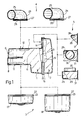
- the set of sectional elements of the invention comprises substantially a pair of basic sectional elements indicated by 1 and 2 and three different series of sectional elements of slightly different dimensions and arranged to be fixed selectively to the two aforesaid basic elements; the sectional elements of the three said series are indicated overall by 3, 4 and 5.
- the basic element 1 is substantially a hollow shell defined by side walls 6, an upper wall 7 and a lower wall 8. Said walls comprise apertures indicated respectively by 9, 10 and 11, and visible in Figure 1.
- the other basic element, indicated by 2 is substantially cup-shaped and is arranged to be fixed to the hollow shell 1 to close the aperture 9 and define therewith an air chamber 13. Said element has a height greater than that of the aperture 9 so that when it is mounted on the hollow shell it defines an air inlet port indicated by 14.
- the hollow shell 1 is provided with an annular flange 15 against which there rests a corresponding flange 16 of the cup-shaped element 2, as shown in Figure 1.
- Each of the two basic elements 1 and 2 is conveniently constructed of thermoplastic material using the normal forming methods for such material. Said two elements can be joined together to form the unit shown in figure 1 by any suitable method, for example by welding, gluing or the like.
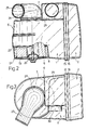
- the sectional elements of the series of elements indicated by 3 are substantially socket-shaped bodies 17 and 18, each of which has a predetermined height which is different from the height of the other and is arranged to be fixed selectively to the hollow shell 1 to close the aperture 11 and to house, together with said hollow shell, an annular-shaped air filter of predetermined height.
- Said filter, indicated by 19, is shown in Figure 2 in which the various sectional elements of the set have been used to form a filter of required dimensions.
- Each of the socket-shaped bodies 17 and 18 is fixed to the hollow shell 1 conveniently by an axial tie bolt 20 passing through a hole in the body.
- each of the socket-shaped bodies 17, 18 is suitably shaped to be able to be housed in the corresponding aperture 11, and for this purpose can have its edge 22 provided with a shoulder 23.
- the sectional elements of the series indicated by 4 are substantially covers 24, each of which is provided with a tubular connector 24 of diameter different from the other and is arranged to be selectively fixed to the hollow shell 1 to close the aperture 10 provided in the upper wall 7.
- the connector 25 is arranged to be connected to a corresponding pipe (not shown) which feeds air to the engine air manifold.
- Each of the covers is provided with an edge 26 having an annular groove 27 arranged to cooperate with the annular edge of the aperture 10.
- the sectional elements of the series indicated by 5 are actual air entry connector elements and each of them is arranged to be selectively fixed to the inlet port 14.
- the shape of each of said connector elements can be slightly different: that of the element shown highest in Figure 1 comprises substantially three flat surfaces 28 defining an air inlet channel; in contrast, the other two elements have an assembly of walls defining a chamber 29 and a pipe stub 30 arranged to be connected to an air intake pipe, conveniently to the pipe of a dynamic air intake device the inlet mouth of which is located in known manner above the vehicle cab.
- Each of said elements is provided with a flange 31 arranged to be connected to the flange 15 of the hollow shell 1.
- the two elements which are lowest in Figure 1 are arranged to be fixed to the hollow shell such that the axis of the pipe stub 30 is horizontal (element in centre) or vertical (element below).
- the set of sectional elements of the invention is used to form a filter suitable for a particular application in the following manner.
- a unit is firstly formed consisting of the two basic elements 1 and 2 as shown in figure 1. Three of the initially described elements pertaining to one of the three series 3, 4 and 5 are then fixed to this unit.
- the element of the series 3 is selected to enable a filter element 19 of a predetermined height to be housed inside the filter.
- the element of the series 4 is selected according to the defined air throughput to be fed to the engine intake manifold, the connectors 25 of the elements of this series having different diameters as stated.
- the element of the series 5 is selected to adapt the filter to either a static air intake (using the element shown highest in Figure 1) or a dynamic air intake having its inlet into the filter on a horizontal axis or on a vertical axis (using one of the other two elements of the series).
Landscapes
- Engineering & Computer Science (AREA)
- Chemical & Material Sciences (AREA)
- Combustion & Propulsion (AREA)
- Mechanical Engineering (AREA)
- General Engineering & Computer Science (AREA)
- Filtering Of Dispersed Particles In Gases (AREA)
Applications Claiming Priority (2)
| Application Number | Priority Date | Filing Date | Title |
|---|---|---|---|
| IT5326388U | 1988-06-28 | ||
| IT5326388U IT214605Z2 (it) | 1988-06-28 | 1988-06-28 | Complesso di elementi componibili atto a realizzare una serie di filtri per l aria alimentata ad un motore a combustione interna di un veicolo pesante |
Publications (2)
| Publication Number | Publication Date |
|---|---|
| EP0348905A1 true EP0348905A1 (de) | 1990-01-03 |
| EP0348905B1 EP0348905B1 (de) | 1992-08-05 |
Family
ID=11281320
Family Applications (1)
| Application Number | Title | Priority Date | Filing Date |
|---|---|---|---|
| EP19890111690 Expired EP0348905B1 (de) | 1988-06-28 | 1989-06-27 | Satz von Segmenten zur Bildung eines Filters für die Verbrennungsluft eines Verbrennungsmotors in einem Lastwagen |
Country Status (4)
| Country | Link |
|---|---|
| EP (1) | EP0348905B1 (de) |
| DE (1) | DE68902370T2 (de) |
| ES (1) | ES2034519T3 (de) |
| IT (1) | IT214605Z2 (de) |
Cited By (1)
| Publication number | Priority date | Publication date | Assignee | Title |
|---|---|---|---|---|
| WO2002031339A1 (de) * | 2000-10-05 | 2002-04-18 | Audi Ag | Gehäuse zur aufnahme eines luftfilterelements |
Citations (1)
| Publication number | Priority date | Publication date | Assignee | Title |
|---|---|---|---|---|
| US2480379A (en) * | 1947-04-14 | 1949-08-30 | Loren W Newberry | Air cleaner |
-
1988
- 1988-06-28 IT IT5326388U patent/IT214605Z2/it active
-
1989
- 1989-06-27 DE DE1989602370 patent/DE68902370T2/de not_active Expired - Fee Related
- 1989-06-27 ES ES89111690T patent/ES2034519T3/es not_active Expired - Lifetime
- 1989-06-27 EP EP19890111690 patent/EP0348905B1/de not_active Expired
Patent Citations (1)
| Publication number | Priority date | Publication date | Assignee | Title |
|---|---|---|---|---|
| US2480379A (en) * | 1947-04-14 | 1949-08-30 | Loren W Newberry | Air cleaner |
Cited By (2)
| Publication number | Priority date | Publication date | Assignee | Title |
|---|---|---|---|---|
| WO2002031339A1 (de) * | 2000-10-05 | 2002-04-18 | Audi Ag | Gehäuse zur aufnahme eines luftfilterelements |
| US6881238B2 (en) | 2000-10-05 | 2005-04-19 | Audi Ag | Housing for receiving an air filter element |
Also Published As
| Publication number | Publication date |
|---|---|
| DE68902370D1 (de) | 1992-09-10 |
| IT214605Z2 (it) | 1990-05-09 |
| DE68902370T2 (de) | 1993-03-18 |
| ES2034519T3 (es) | 1993-04-01 |
| IT8853263V0 (it) | 1988-06-28 |
| EP0348905B1 (de) | 1992-08-05 |
Similar Documents
| Publication | Publication Date | Title |
|---|---|---|
| US3890232A (en) | Fluid filter | |
| US4805564A (en) | Engine intake manifold assembly | |
| DE3713276C2 (de) | Brennstoffördereinrichtung für eine Brennkraftmaschine | |
| US3841489A (en) | Fluid filter | |
| US5820646A (en) | Inline filter apparatus | |
| US5002030A (en) | Fuel rail assemblies for internal combustion engines | |
| DE69002928T2 (de) | Hochdruckschlauch für ein modulares Benzinzuführungssystem. | |
| US6024066A (en) | Air-intake module for internal combustion engine | |
| US6167855B1 (en) | Integrated air-fuel module and assembly method | |
| EP2069042B1 (de) | Vorrichtung zum abscheiden von partikeln aus einem gasstrom | |
| DE69802406T2 (de) | Integrierte brennkraftmaschinenansaugssammelleitung mit einem entlüftungsventil für brennstoffdampf und ein abgasrückführventil | |
| EP1306829B1 (de) | Vorrichtung zur Übertragung von Brennkraftmaschinengeräuschen | |
| DE4403219A1 (de) | Als Baueinheit vorfertigbares Saugmodul für eine Mehrzylnder-Brennkraftmaschine | |
| EP1399240B1 (de) | Filterelement mit drainagerohr | |
| GB2108767A (en) | Electromagnetically actuable valve | |
| US20020166809A1 (en) | Fine filter for a fuel feed unit | |
| DE10032806A1 (de) | Kraftfahrzeug | |
| EP1322855B1 (de) | Gehäuse zur aufnahme eines luftfilterelements | |
| EP1201287B1 (de) | Gefaltete Luftfiltervorrichtung | |
| US6553973B1 (en) | Fuel tank cover and filter assembly for fuel tank | |
| EP1647320B1 (de) | Tankbelüftungsfilter | |
| EP0348905B1 (de) | Satz von Segmenten zur Bildung eines Filters für die Verbrennungsluft eines Verbrennungsmotors in einem Lastwagen | |
| EP1415081A1 (de) | Kraftstofffördereinrichtung für ein kraftfahrzeug | |
| US20210180547A1 (en) | Space optimizing air filter | |
| EP0856102A1 (de) | Saugrohr |
Legal Events
| Date | Code | Title | Description |
|---|---|---|---|
| PUAI | Public reference made under article 153(3) epc to a published international application that has entered the european phase |
Free format text: ORIGINAL CODE: 0009012 |
|
| AK | Designated contracting states |
Kind code of ref document: A1 Designated state(s): DE ES FR GB IT NL SE |
|
| 17P | Request for examination filed |
Effective date: 19900620 |
|
| 17Q | First examination report despatched |
Effective date: 19911007 |
|
| GRAA | (expected) grant |
Free format text: ORIGINAL CODE: 0009210 |
|
| AK | Designated contracting states |
Kind code of ref document: B1 Designated state(s): DE ES FR GB IT NL SE |
|
| ET | Fr: translation filed | ||
| REF | Corresponds to: |
Ref document number: 68902370 Country of ref document: DE Date of ref document: 19920910 |
|
| ITF | It: translation for a ep patent filed | ||
| REG | Reference to a national code |
Ref country code: ES Ref legal event code: FG2A Ref document number: 2034519 Country of ref document: ES Kind code of ref document: T3 |
|
| PLBE | No opposition filed within time limit |
Free format text: ORIGINAL CODE: 0009261 |
|
| STAA | Information on the status of an ep patent application or granted ep patent |
Free format text: STATUS: NO OPPOSITION FILED WITHIN TIME LIMIT |
|
| 26N | No opposition filed | ||
| EAL | Se: european patent in force in sweden |
Ref document number: 89111690.7 |
|
| REG | Reference to a national code |
Ref country code: GB Ref legal event code: IF02 |
|
| NLT1 | Nl: modifications of names registered in virtue of documents presented to the patent office pursuant to art. 16 a, paragraph 1 |
Owner name: IVECO S.P.A. |
|
| REG | Reference to a national code |
Ref country code: FR Ref legal event code: CD |
|
| PG25 | Lapsed in a contracting state [announced via postgrant information from national office to epo] |
Ref country code: IT Free format text: LAPSE BECAUSE OF NON-PAYMENT OF DUE FEES;WARNING: LAPSES OF ITALIAN PATENTS WITH EFFECTIVE DATE BEFORE 2007 MAY HAVE OCCURRED AT ANY TIME BEFORE 2007. THE CORRECT EFFECTIVE DATE MAY BE DIFFERENT FROM THE ONE RECORDED. Effective date: 20050627 |
|
| PGFP | Annual fee paid to national office [announced via postgrant information from national office to epo] |
Ref country code: GB Payment date: 20060526 Year of fee payment: 18 |
|
| PGFP | Annual fee paid to national office [announced via postgrant information from national office to epo] |
Ref country code: ES Payment date: 20060615 Year of fee payment: 18 |
|
| PGFP | Annual fee paid to national office [announced via postgrant information from national office to epo] |
Ref country code: NL Payment date: 20060627 Year of fee payment: 18 |
|
| PGFP | Annual fee paid to national office [announced via postgrant information from national office to epo] |
Ref country code: SE Payment date: 20070601 Year of fee payment: 19 |
|
| PGFP | Annual fee paid to national office [announced via postgrant information from national office to epo] |
Ref country code: DE Payment date: 20070628 Year of fee payment: 19 |
|
| GBPC | Gb: european patent ceased through non-payment of renewal fee |
Effective date: 20070627 |
|
| NLV4 | Nl: lapsed or anulled due to non-payment of the annual fee |
Effective date: 20080101 |
|
| PG25 | Lapsed in a contracting state [announced via postgrant information from national office to epo] |
Ref country code: NL Free format text: LAPSE BECAUSE OF NON-PAYMENT OF DUE FEES Effective date: 20080101 |
|
| PGFP | Annual fee paid to national office [announced via postgrant information from national office to epo] |
Ref country code: FR Payment date: 20070601 Year of fee payment: 19 |
|
| PG25 | Lapsed in a contracting state [announced via postgrant information from national office to epo] |
Ref country code: GB Free format text: LAPSE BECAUSE OF NON-PAYMENT OF DUE FEES Effective date: 20070627 |
|
| REG | Reference to a national code |
Ref country code: ES Ref legal event code: FD2A Effective date: 20070628 |
|
| PG25 | Lapsed in a contracting state [announced via postgrant information from national office to epo] |
Ref country code: ES Free format text: LAPSE BECAUSE OF NON-PAYMENT OF DUE FEES Effective date: 20070628 |
|
| EUG | Se: european patent has lapsed | ||
| REG | Reference to a national code |
Ref country code: FR Ref legal event code: ST Effective date: 20090228 |
|
| PG25 | Lapsed in a contracting state [announced via postgrant information from national office to epo] |
Ref country code: DE Free format text: LAPSE BECAUSE OF NON-PAYMENT OF DUE FEES Effective date: 20090101 |
|
| PG25 | Lapsed in a contracting state [announced via postgrant information from national office to epo] |
Ref country code: FR Free format text: LAPSE BECAUSE OF NON-PAYMENT OF DUE FEES Effective date: 20080630 |
|
| PG25 | Lapsed in a contracting state [announced via postgrant information from national office to epo] |
Ref country code: SE Free format text: LAPSE BECAUSE OF NON-PAYMENT OF DUE FEES Effective date: 20080628 |
|
| PGFP | Annual fee paid to national office [announced via postgrant information from national office to epo] |
Ref country code: IT Payment date: 20070627 Year of fee payment: 19 |
|
| PGRI | Patent reinstated in contracting state [announced from national office to epo] |
Ref country code: IT Effective date: 20110616 |
|
| PGRI | Patent reinstated in contracting state [announced from national office to epo] |
Ref country code: IT Effective date: 20110616 |