EP0348711B1 - Device for axially shifting rolls in the stand of a rolling mill - Google Patents
Device for axially shifting rolls in the stand of a rolling mill Download PDFInfo
- Publication number
- EP0348711B1 EP0348711B1 EP89110436A EP89110436A EP0348711B1 EP 0348711 B1 EP0348711 B1 EP 0348711B1 EP 89110436 A EP89110436 A EP 89110436A EP 89110436 A EP89110436 A EP 89110436A EP 0348711 B1 EP0348711 B1 EP 0348711B1
- Authority
- EP
- European Patent Office
- Prior art keywords
- bearing
- axial
- stand
- rolls
- roller
- Prior art date
- Legal status (The legal status is an assumption and is not a legal conclusion. Google has not performed a legal analysis and makes no representation as to the accuracy of the status listed.)
- Expired - Lifetime
Links
- 238000005096 rolling process Methods 0.000 title claims abstract description 21
- 238000006073 displacement reaction Methods 0.000 claims description 25
- 238000005097 cold rolling Methods 0.000 claims description 3
- 238000005098 hot rolling Methods 0.000 claims description 3
- 238000005265 energy consumption Methods 0.000 abstract 1
- 230000033001 locomotion Effects 0.000 description 4
- 238000010276 construction Methods 0.000 description 2
- 238000007789 sealing Methods 0.000 description 2
- 230000005540 biological transmission Effects 0.000 description 1
- 238000011109 contamination Methods 0.000 description 1
- 239000000428 dust Substances 0.000 description 1
- 238000012423 maintenance Methods 0.000 description 1
- 239000000463 material Substances 0.000 description 1
Images
Classifications
-
- B—PERFORMING OPERATIONS; TRANSPORTING
- B21—MECHANICAL METAL-WORKING WITHOUT ESSENTIALLY REMOVING MATERIAL; PUNCHING METAL
- B21B—ROLLING OF METAL
- B21B31/00—Rolling stand structures; Mounting, adjusting, or interchanging rolls, roll mountings, or stand frames
- B21B31/16—Adjusting or positioning rolls
- B21B31/18—Adjusting or positioning rolls by moving rolls axially
-
- B—PERFORMING OPERATIONS; TRANSPORTING
- B21—MECHANICAL METAL-WORKING WITHOUT ESSENTIALLY REMOVING MATERIAL; PUNCHING METAL
- B21B—ROLLING OF METAL
- B21B31/00—Rolling stand structures; Mounting, adjusting, or interchanging rolls, roll mountings, or stand frames
- B21B31/07—Adaptation of roll neck bearings
Definitions
- the invention relates to a device for the axial displacement of rolls in the stand of a rolling mill according to the preamble of claim 1; See GB-A 2 024 454.
- axial displacements of the rolls, especially the work rolls are necessary . Therefore, as can be seen, for example, from DE-OS 35 21 180, a device for the axial displacement of rolls in roll stands has been designed, in which the rolls are held in special chocks via their radial and axial bearings, which in turn are held in the roll stands of the rolling stand arranged sliding guides and sliding carriages are slidably guided.
- the chocks hydraulic piston-cylinder units articulated, which are attached to the outside of the roll stand.
- FIG. 4 shows that the bearing chock is fixed in the frame and the inner bearing ring of the radial bearing, which is designed as a roller bearing and is attached to the bearing journal of the roller, is axially movable relative to the outer bearing ring of the radial bearing or vice versa.
- the thrust bearing is very complicated with a large number of individual actuators arranged within its housing, which leads to the fact that these, including the integrated displacement sensors, are extremely difficult to access and difficult to maintain.
- the object of the invention is to provide a device for the axial displacement of rolls in a stand of a rolling mill, which is free from these known disadvantages mentioned above and is particularly characterized by its very simple construction and easy access to the hydraulic and mechanical components.
- the axial forces to be applied by the displacement system for axially displacing the roller can therefore be kept lower in the bearing system on which the invention is based in comparison with roller displacement devices with axially displaceable chocks, and energy and costs can thereby be saved, in particular if, as in the arrangement on which the invention is based, the displacement system as a hydraulic pressure system in Thrust bearing is integrated.
- the hydraulic pressure system integrated in the axial bearing consists of a double-acting piston-cylinder unit, the outer bearing ring of the axial bearing is designed as a piston and the bearing housing surrounding it is designed as a cylinder.
- the outer bearing ring designed as a piston and the bearing housing of the axial bearing designed as a cylinder are made in several parts. In this way, the maintenance and replacement of the bearing or the hydraulic pressure system or parts thereof considerably relieved.
- the radial bearings are, according to a further advantageous embodiment of the invention, with several, in rows in the axial direction at a distance bearing bodies arranged from each other. It is also particularly expedient to use a cylindrical roller bearing or a radial bearing designed as a needle roller bearing.
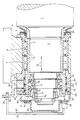
- the drawing shows a section of a roller (1) of a rolling mill with a bearing journal (2) which is tapered in a step-like manner at the left end and is mounted in a radial bearing (3) and an axial bearing (4) shown in longitudinal section.
- the right end of the roller (1) which is not shown in the drawing, is provided with a single-stage bearing journal which is mounted in a radial bearing of the same design as the radial bearing (3).
- These radial bearings (3) consist of an inner, relatively long, attached to the bearing journal (2) trained bearing ring (5) and two outer bearing rings (7, 8) arranged in the stand (6) of the rolling mill and from the intermediate bearing bodies (9) arranged in four rows at a distance from one another.
- This inventive design of the radial bearing (3) very advantageously allows an axial displacement (arrows 10) of the roller (1) together with the inner bearing ring (5) relative to the outer, two-part bearing ring (7, 8) without it to the undesirably disadvantageous, energy-consuming sliding friction between the bearing rings (5) and (7, 8), since the axial movement of the inner bearing ring (5) relative to the outer bearing ring (7, 8) is absorbed by the bearing bodies (9) and into one Rolling motion is converted from very little friction.
- the radial bearings (3) are expediently designed as cylindrical roller bearings in order to be able to reliably absorb and compensate for the high loads occurring on the rollers during operation of the rolling mill.
- other roller bearings such as needle roller bearings, barrel roller bearings, etc. in a single or multi-row arrangement can also advantageously be used as radial bearings.
- the axial bearing (4) with integrated hydraulic bearings which is also shown in longitudinal section in the drawing and is arranged on the left-hand side and is firmly connected to the stepped bearing journal (2) Printing system provided.
- This axial bearing (4) consists of an inner bearing ring (11) attached to the bearing journal (2), which counteracts axial displacement on the journal (2) is secured by support and retaining rings (12, 13, 14, 15), and from an outer bearing ring (16) with intermediate support rings (17) and bearing rollers (18).
- the outer bearing roller support ring (17) is supported in the axial direction by a ring (19) with a flange which is firmly connected to the outer bearing ring (16).
- the outer bearing ring (16) of the axial bearing (4) is provided on the outside with an annular extension (20) with a sealing ring (21) which is slidably guided in an axially movable manner in a cylindrical recess (22) of the bearing housing (23).
- an annular disc (24) with a sealing ring (25) is attached, which seals the cylindrical recess (22) in the bearing housing (23) to the outside in a pressure-tight manner.
- the axial displacement path of the roller (1) which in practice lies between about 0 and 400 mm, can be easily monitored and adjusted and / or adjusted at any time even during the rolling operation.
- the bearing housing (23) is sealed to the outside by an end cover (35) and between the roller body (1) and the roll stand (6) there is a rubber for this -elastic cuff (36) arranged.
- the device designed according to the invention can be used not only very advantageously for the axial displacement of work rolls and backup rolls in the stand of a hot or cold rolling mill, but also in rolling mills, for. B. for crushing hard materials or the like.
- the device according to the invention is particularly characterized by its very simple and compact, after externally closed, easily accessible, easy to assemble or disassemble and easy to maintain design that can be retrofitted to existing rolling mills at any time.
- the roller shifting device according to the invention can be used very advantageously in duo, four-high, six-high and special rolling mills.
- the measures according to the invention are not limited to the exemplary embodiment shown in the drawing figure.
- the radial bearings can have any shape, for example several radial bearings can also lie one above the other.
- the respective structural design is left to the person skilled in the art to adapt to the specific use.
Abstract
Description
Die Erfindung bezieht sich auf eine Vorrichtung zum axialen Verschieben von Walzen im Gerüst eines Walzwerkes gemäß Oberbegriff von Patentanspruch 1; Siehe GB-A 2 024 454.The invention relates to a device for the axial displacement of rolls in the stand of a rolling mill according to the preamble of
Um die im Betrieb eines Walzwerkes unerwünschten und nachteiligen Einflüsse wie Thermik, Durchbiegung der Arbeitswalzen oder des Walzensatzes, Verschleiß, Riefenbildung an den Walzenoberflächen etc. auszugleichen bzw. auszuschalten und ein optimal geformtes Walzprodukt zu erreichen, sind axiale Verschiebungen der Walzen, insbesondere der Arbeitswalzen erforderlich. Man hat daher, wie beispielsweise der DE-OS 35 21 180 zu entnehmen ist, eine Vorrichtung zum axialen Verschieben von Walzen in Walzgerüsten konzipiert, bei der die Walzen über ihre Radial- und Axiallager in besonderen Einbaustücken gehalten sind, die ihrerseits über in den Walzständern des Walzgerüstes angeordneten Gleitführungen und Schiebeschlitten gleitend geführt sind. Zum axialen Verschieben der Walzen sind an den Einbaustücken hydraulische Kolben-Zylinderaggregate angelenkt, die außen am Walzgerüst befestigt sind.In order to compensate or eliminate the undesirable and disadvantageous influences such as thermals, deflection of the work rolls or the set of rolls, wear, scoring on the roll surfaces etc. in order to achieve an optimally shaped rolled product, axial displacements of the rolls, especially the work rolls, are necessary . Therefore, as can be seen, for example, from DE-OS 35 21 180, a device for the axial displacement of rolls in roll stands has been designed, in which the rolls are held in special chocks via their radial and axial bearings, which in turn are held in the roll stands of the rolling stand arranged sliding guides and sliding carriages are slidably guided. For the axial displacement of the rollers are on the chocks hydraulic piston-cylinder units articulated, which are attached to the outside of the roll stand.
Da bei dieser bekannten Vorrichtung die axiale Verschiebung der Walzen in sogenannten Gleitbahnen erfolgt, müssen aufgrund der hierbei auftretenden Gleitreibung von den hydraulischen Kolben- Zylinderaggregaten zusätzliche und verhältnismäßig hohe Axialkräfte aufgebracht werden, was mit erhöhtem Energie- und Kostenaufwand verbunden ist. Ferner ist diese bekannte Verschiebevorrichtung von Walzen im konstruktiven Aufbau kompliziert und aufgrund der am Walzengerüst außen angeordneten und nach außen weit vorstehenden hydraulischen sowie mechanischen Verschiebeelemente schwer zugänglich und entsprechend schwierig zu warten.Since in this known device the axial displacement of the rollers takes place in so-called slideways, additional and relatively high axial forces have to be applied by the hydraulic piston-cylinder units due to the sliding friction which occurs, which is associated with increased energy and cost expenditure. Furthermore, this known shifting device of rollers is complicated in terms of its construction and is difficult to access and correspondingly difficult to maintain due to the hydraulic and mechanical shifting elements arranged on the outside of the roller stand and projecting outward to the outside.
Ferner ist aus der US-PS 4 491 005 eine Vorrichtung zum axialen Verschieben der Arbeitswalzen im Gerüst eines Walzwerkes bekannt, bei der die Walzen mit ihren Lagern über in Gleitbahnen geführten Einbaustücken axial beweglich angeordnet sind. Da beim axialen Verschieben der Walzen auch hierbei die Reibungswiderstände in den Gleitbahnen von den ebenfalls außen am Walzgerüst angeordneten hydraulischen Verschiebeaggregaten durch erhöhten Energieaufwand überwunden werden müssen, ist auch dieses bekannte Walzen-Verschiebesystem mit denselben Nachteilen behaftet, wie die aus der DE-OS 35 21 180 bekannte Walzen-Verschiebevorrichtung.Furthermore, from US Pat. No. 4,491,005 a device for axially displacing the work rolls in the stand of a rolling mill is known, in which the rolls with their bearings are arranged so as to be axially movable via chocks guided in slideways. Since the axial resistance of the rollers also has to overcome the frictional resistance in the slideways of the hydraulic displacement units, which are also arranged on the outside of the roll stand, by increased energy expenditure, this known roller displacement system also has the same disadvantages afflicted, such as the roller displacement device known from DE-OS 35 21 180.
Aus der GB-A-2 024 454 ist eine Vorrichtung zum axialen Verschieben von Walzen im Gerüst eines Walzwerkes bekannt, insbesondere der Arbeitswalzen eines Warm- oder Kaltwalzwerkes, wobei die Walzen an ihren als Lagerzapfen ausgebildeten Enden in Radiallagern gelagert und zusätzlich mit einem Axiallager versehen sind, über das ein Verschiebesystem an der Walze angreift. Dabei werden
einerseits Lösungen gezeigt, bei denen die Walzen zusammen mit ihren Lagern in Einbaustücken im Gerüst verschoben werden. Andererseits zeigt Figur 4, daß das Lagereinbaustück im Gerüst festgelegt und der innere am Lagerzapfen der Walze befestigte Lagerring des als Wälzlager ausgebildeen Radiallagers gegenüber dem äußeren Lagerring des Radiallagers oder umgekehrt axialbeweglich angeordnet ist. Das Axiallager ist sehr kompliziert mit einer größeren Zahl innerhalb seines Gehäuses angeordneten einzelnen Stellgliedern aufgebaut, was dazu führt, daß diese einschließlich der integrierten Weggeber äußerst schwer zugänglich und schwierig zu warten sind.From GB-A-2 024 454 a device for the axial displacement of rolls in the stand of a rolling mill is known, in particular the work rolls of a hot or cold rolling mill, the rolls being mounted in radial bearings at their ends designed as bearing journals and additionally provided with an axial bearing are over which a displacement system acts on the roller. In doing so
On the one hand, solutions were shown in which the rollers and their bearings are moved in chocks in the stand. On the other hand, FIG. 4 shows that the bearing chock is fixed in the frame and the inner bearing ring of the radial bearing, which is designed as a roller bearing and is attached to the bearing journal of the roller, is axially movable relative to the outer bearing ring of the radial bearing or vice versa. The thrust bearing is very complicated with a large number of individual actuators arranged within its housing, which leads to the fact that these, including the integrated displacement sensors, are extremely difficult to access and difficult to maintain.
Ausgehend von diesen bekannten Vorrichtungen besteht die Aufgabe der Erfindung darin, eine Vorrichtung zum axialen Verschieben von Walzen in einem Gerüst eines Walzwerkes zu schaffen, die frei von diesen oben angeführten bekannten Nachteilen ist und sich besonders durch ihren sehr einfachen konstruktiven Aufbau sowie leichte Zugänglichkeit der hydraulischen sowie mechanischen Bauteile auszeichnet.Based on these known devices, the object of the invention is to provide a device for the axial displacement of rolls in a stand of a rolling mill, which is free from these known disadvantages mentioned above and is particularly characterized by its very simple construction and easy access to the hydraulic and mechanical components.
Diese Aufgabe wird bei einer Vorrichtung zum axialen Verschieben von Walzen im Gerüst eines Walzwerks nach dem Oberbegriff von Anspruch 1 mit einer Ausführung entsprechend den im Kennzeichnungsteil angegebenen Merkmalen gelöst.This object is achieved in a device for the axial displacement of rolls in the stand of a rolling mill according to the preamble of
Dadurch, daß der innere am Lagerzapfen der Walze befestigte Lagerring des als Wälzlager ausgebildeten Radiallagers gegenüber dem äußeren Lagerring axialbeweglich angeordnet ist, tritt beim axialen Verschieben der Walze praktisch keine Gleitreibung auf, da die axiale Bewegung des inneren Lagerringes gegenüber dem äußeren Lagerring von den zwischen den Lagerringen befindlichen Lagerkörpern durch ihre Abrollbewegungen kompensiert wird. Es kommt somit bei
der axialen Verschiebung der Walze allenfalls zu einer geringen Lagerrollenreibung in den Radiallagern der Walze, deren Überwindung jedoch kaum nennenswerte Axialkräfte erfordern. Die vom Verschiebesystem aufzubringenden Axialkräfte zum axialen Verschieben der Walze können daher bei dem der Erfindung zugrundeliegenden Lagersytem im Vergleich zu Walzenverschiebeeinrichtungen mit axialverschiebbaren Einbaustücken niedriger gehalten und dadurch Energie und Kosten eingespart werden, insbesondere wenn wie bei der der Erfindung zugrundeliegenden Anordnung das Verschiebesystem als hydraulisches Drucksystem im Axiallager integriert ist.Characterized in that the inner bearing ring of the roller bearing designed as a roller bearing is axially movable relative to the outer bearing ring, practically no sliding friction occurs when the roller is axially displaced, since the axial movement of the inner bearing ring relative to the outer bearing ring of the between the Bearing rings located bearing bodies is compensated for by their rolling movements. It comes with
the axial displacement of the roller at most to a low bearing roller friction in the radial bearings of the roller, the overcoming of which, however, hardly requires any significant axial forces. The axial forces to be applied by the displacement system for axially displacing the roller can therefore be kept lower in the bearing system on which the invention is based in comparison with roller displacement devices with axially displaceable chocks, and energy and costs can thereby be saved, in particular if, as in the arrangement on which the invention is based, the displacement system as a hydraulic pressure system in Thrust bearing is integrated.
Dabei wird erfindungsgemäß eine weitere Verbesserung und Vereinfachung dadurch erreicht, daß das im Axiallager integrierte hydraulische Drucksystem aus einer doppeltwirkenden Kolben-Zylindereinheit besteht, wobei der äußere Lagerring des Axiallagers als Kolben und das ihn umgebende Lagergehäuse als Zylinder ausgebildet ist.According to the invention, a further improvement and simplification is achieved in that the hydraulic pressure system integrated in the axial bearing consists of a double-acting piston-cylinder unit, the outer bearing ring of the axial bearing is designed as a piston and the bearing housing surrounding it is designed as a cylinder.
Durch diese Ausbildung und Anordnung des hydraulischen Drucksystems im Axiallager wird in besonders einfacher Weise eine unmittelbare, direkte und nahezu reibungslose Übertragung der vom Drucksystem ausgehenden, in axialer Richtung wirkenden Druckkräfte auf die Walze erreicht und ein im konstruktiven Aufbau einfaches, besonders kompaktes und nach außen geschlossenes Walzenverschiebesystem vorgestellt, das nicht nur leichter zugänglich und wartungsfreundlicher als die bisher bekannten Walzenverschiebevvorichtungen, sondern diesen gegenüber auch dynamisch schneller und in seiner Funktionsweise sicherer ist.Through this design and arrangement of the hydraulic pressure system in the axial bearing, an immediate, direct and almost smooth transmission of the compressive forces acting in the axial direction from the pressure system to the roller is achieved in a particularly simple manner, and a structurally simple, particularly compact and closed to the outside Roll shifting system presented, which is not only more easily accessible and easier to maintain than the previously known roll shifting devices, but is also dynamically faster and safer in its operation.
In weiterer Ausgestaltung der Erfindung sind der als Kolben ausgebildete äußere Lagerring und das als Zylinder ausgebildete Lagergehäuse des Axiallagers mehrteilig ausgebildet. Auf diese Weise wird die Wartung sowie das Auswechseln des Lagers oder des hydraulischen Drucksystems oder von Teilen davon erheblich erleichtert.In a further embodiment of the invention, the outer bearing ring designed as a piston and the bearing housing of the axial bearing designed as a cylinder are made in several parts. In this way, the maintenance and replacement of the bearing or the hydraulic pressure system or parts thereof considerably relieved.
Um die im Betrieb des Walzwerkes von den Walzen ausgehenden, auf die Radiallager häufig mit stark schwankender Intensität wirkenden Druckbelastungen von den Radiallagern sicher und dauerhaft aufnehmen zu können, sind die Radiallager nach einer weiteren vorteilhaften Ausgestaltung der Erfindung mit mehreren, in Reihen in Achsrichtung mit Abstand voneinander angeordneten Lagerkörpern ausgestattet. Es ist hierbei auch besonders zweckmäßig als Zylinderrollenlager oder als Nadellager ausgebildete Radiallager einzusetzen.In order to be able to safely and permanently absorb the pressure loads emanating from the rollers during operation of the rolling mill, which often act on the radial bearings with strongly fluctuating intensity, the radial bearings are, according to a further advantageous embodiment of the invention, with several, in rows in the axial direction at a distance bearing bodies arranged from each other. It is also particularly expedient to use a cylindrical roller bearing or a radial bearing designed as a needle roller bearing.
Die Vorrichtung zum axialen Verschieben von Walzen im Gerüst eines Walzwerkes gemäß der Erfindung wird nachfolgend anhand eines in der Zeichnung schematisch dargestellten Ausführungsbeispieles näher erläutert.The device for the axial displacement of rolls in the stand of a rolling mill according to the invention is explained in more detail below with reference to an embodiment shown schematically in the drawing.
Die Zeichnung zeigt ein Teilstück einer Walze (1) eines Walzwerkes mit einem am linken Ende stufenförmig verjüngt ausgebildeten Lagerzapfen (2), der in einem im Längsschnitt dargestellten Radiallager (3) und einem Axiallager (4) gelagert ist. Das in der Zeichnung nicht näher dargestellte rechte Ende der Walze (1) ist mit einem einstufig ausgebildeten Lagerzapfen versehen, der in einem ebenso ausgebildetem Radiallager gelagert ist, wie das Radiallager (3).The drawing shows a section of a roller (1) of a rolling mill with a bearing journal (2) which is tapered in a step-like manner at the left end and is mounted in a radial bearing (3) and an axial bearing (4) shown in longitudinal section. The right end of the roller (1), which is not shown in the drawing, is provided with a single-stage bearing journal which is mounted in a radial bearing of the same design as the radial bearing (3).
Diese Radiallager (3) bestehen aus einem inneren, am Lagerzapfen (2) befestigten, verhältnismäßig lang ausgebildeten Lagerring (5) und zwei äußeren, im Gerüst (6) des Walzwerkes angeordneten Lagerringen (7, 8) sowie aus den dazwischenliegenden, in vier Reihen mit Abstand nebeneinander angeordneten Lagerkörpern (9). Diese erfindungsgemäße Ausbildung der Radiallager (3) ermöglicht sehr vorteilhaft eine axiale Verschiebung (Pfeile 10) der Walze (1) zusammen mit dem inneren Lagerring (5) gegenüber dem äußeren, aus zwei Teilen bestehenden Lagerring (7, 8), ohne daß es dabei zu den unerwünscht nachteiligen, energieverbrauchenden Gleitreibungen zwischen den Lagerringen (5) und (7, 8) kommt, da die axiale Bewegung des inneren Lagerringes (5) gegenüber dem äußeren Lagerring (7, 8) von den Lagerkörpern (9) aufgenommen und in eine Rollbewegung von sehr geringer Reibung umgewandelt wird. Die Radiallager (3) sind hierbei zweckmäßigerweise als Zylinderrollenlager ausgebildet, um die im Betrieb des Walzwerkes an den Walzen auftretenden hohen Belastungen sicher aufnehmen und kompensieren zu können. Als Radiallager können selbstverständlich auch andere Wälzlager wie Nadellager, Tonnenlager etc. in ein- oder mehrreihiger Anordnung nebeneinander mit Vorteil eingesetzt werden.These radial bearings (3) consist of an inner, relatively long, attached to the bearing journal (2) trained bearing ring (5) and two outer bearing rings (7, 8) arranged in the stand (6) of the rolling mill and from the intermediate bearing bodies (9) arranged in four rows at a distance from one another. This inventive design of the radial bearing (3) very advantageously allows an axial displacement (arrows 10) of the roller (1) together with the inner bearing ring (5) relative to the outer, two-part bearing ring (7, 8) without it to the undesirably disadvantageous, energy-consuming sliding friction between the bearing rings (5) and (7, 8), since the axial movement of the inner bearing ring (5) relative to the outer bearing ring (7, 8) is absorbed by the bearing bodies (9) and into one Rolling motion is converted from very little friction. The radial bearings (3) are expediently designed as cylindrical roller bearings in order to be able to reliably absorb and compensate for the high loads occurring on the rollers during operation of the rolling mill. Of course, other roller bearings such as needle roller bearings, barrel roller bearings, etc. in a single or multi-row arrangement can also advantageously be used as radial bearings.
Zum axialen Verschieben der Walze (1) im Gerüst (6) des Walzwerkes ist gemäß der Erfindung das in der Zeichnung ebenfalls im Längsschnitt dargestellte, auf der linken Seite angeordnete, mit dem abgestuften Lagerzapfen (2) fest verbundene Axiallager (4) mit integrierten hydraulischen Drucksystem vorgesehen. Dieses Axiallager (4) besteht aus einem inneren, am Lagerzapfen (2) befestigten Lagerring (11), der gegen axiales Verschieben auf dem Lagerzapfen (2) durch Stütz- und Halteringe (12, 13, 14, 15) gesichert ist, sowie aus einem äußeren Lagerring (16) mit dazwischenliegenden Stützringen (17) und Lagerrollen (18). Der äußere Lagerrollenstützring (17) wird hierbei durch einen mit dem äußeren Lagerring (16) fest verbundenen Ring (19) mit Flansch in axialer Richtung abgestützt. Der äußere Lagerring (16) des Axiallagers (4) ist außen mit einem ringförmigen Fortsatz (20) mit Dichtring (21) versehen, der in einer zylinderförmigen Ausnehmung (22) des Lagergehäuses (23) axialbeweglich gleitend geführt ist. An der äußeren Stirnseite des Lagergehäuses (23), das seinerseits am Walzgerüst (6) befestigt ist, ist eine Ringscheibe (24) mit Dichtring (25) angebracht, die die zylinderförmige Ausnehmung (22) im Lagergehäuse (23) nach außen druckdicht abschließt. Der äußere Lagerring (16) mit dem ringförmigen Fortsatz (20) und das Lagergehäuse (23) mit Ringscheibe (24) bilden zusammen die doppeltwirkende Kolben-Zylindereinheit des hydraulischen Drucksystems, wobei der ringförmige Fortsatz (20) die Funktion des Kolbens und die Ausnehmung (22) im Lagergehäuse (23) die Funktion des Zylinders ausübt.For the axial displacement of the roller (1) in the stand (6) of the rolling mill, according to the invention, the axial bearing (4) with integrated hydraulic bearings, which is also shown in longitudinal section in the drawing and is arranged on the left-hand side and is firmly connected to the stepped bearing journal (2) Printing system provided. This axial bearing (4) consists of an inner bearing ring (11) attached to the bearing journal (2), which counteracts axial displacement on the journal (2) is secured by support and retaining rings (12, 13, 14, 15), and from an outer bearing ring (16) with intermediate support rings (17) and bearing rollers (18). The outer bearing roller support ring (17) is supported in the axial direction by a ring (19) with a flange which is firmly connected to the outer bearing ring (16). The outer bearing ring (16) of the axial bearing (4) is provided on the outside with an annular extension (20) with a sealing ring (21) which is slidably guided in an axially movable manner in a cylindrical recess (22) of the bearing housing (23). On the outer end face of the bearing housing (23), which in turn is attached to the roll stand (6), an annular disc (24) with a sealing ring (25) is attached, which seals the cylindrical recess (22) in the bearing housing (23) to the outside in a pressure-tight manner. The outer bearing ring (16) with the ring-shaped extension (20) and the bearing housing (23) with ring washer (24) together form the double-acting piston-cylinder unit of the hydraulic pressure system, the ring-shaped extension (20) functioning as the piston and the recess ( 22) in the bearing housing (23) performs the function of the cylinder.
Im Lagergehäuse (23) sind ferner für die Zufuhr des hydraulischen Druckmediums in diese doppeltwirkende Kolben-Zylindereinheit Bohrungen (26, 27) angeordnet, die zu beiden Seiten des ringförmigen Fortzsatzes (20) in die Ausnehmung (22) des äußeren Lagerringes (23) münden. An diese Bohrungen (26, 27) sind außen Druckleitungen (28, 29) angeschlossen, die unter Zwischenschaltung einer Schiebersteuerung (30) mit einem in der Zeichnung nicht dargestellten Pumpaggregat in Verbindung stehen und über die die hydraulisch doppelwirkende Kolben-Zylindereinheit mit Druckmedium beaufschlagt wird und die Walze (1) in axialer Richtung verschiebt. Diese in ihrer Funktionsweise an sich allgemein bekannte, elektromagnetisch arbeitende Schiebersteuerung (30) ist über elektrische Leitungen (31, 32) mit einem Weggeber (33) verbunden, der an einem am Lagergehäuse (23) angeordneten Ringdeckel (34) befestigt ist.In the bearing housing (23) for the supply of the hydraulic pressure medium in this double-acting piston-cylinder unit holes (26, 27) are arranged, which open on both sides of the annular extension (20) in the recess (22) of the outer bearing ring (23) . Pressure pipes (28, 29) are connected to these bores (26, 27) on the outside Interposition of a slide control (30) with a pump unit, not shown in the drawing, and via which the hydraulic double-acting piston-cylinder unit is pressurized with pressure medium and moves the roller (1) in the axial direction. This functionally known, electromagnetically operating slide control (30) is connected via electrical lines (31, 32) to a displacement sensor (33) which is attached to an annular cover (34) arranged on the bearing housing (23).
Mit Hilfe des Weggebers (33) kann sehr vorteilhaft der in der Praxis zwischen etwa 0 und 400 mm liegende axiale Verschiebeweg der Walze (1) leicht überwacht und jederzeit auch während des Walzbetriebes eingestellt und/oder verstellt werden. Zum Schutz der Lager, Lagerteile und des hydraulischen Drucksystems vor Staub oder sonstiger Verschmutzung ist ferner das Lagergehäuse (23) durch einen Stirndeckel (35) nach außen hin dicht abgeschlossen und zwischen dem Walzenkörper (1) und dem Walzgerüst (6) ist hierfür eine gummi-elastische Manschette (36) angeordnet.With the aid of the travel sensor (33), the axial displacement path of the roller (1), which in practice lies between about 0 and 400 mm, can be easily monitored and adjusted and / or adjusted at any time even during the rolling operation. To protect the bearings, bearing parts and the hydraulic pressure system from dust or other contamination, the bearing housing (23) is sealed to the outside by an end cover (35) and between the roller body (1) and the roll stand (6) there is a rubber for this -elastic cuff (36) arranged.
Im ürigen kann die erfindungsgemäß ausgebildete Vorrichtung nicht nur sehr vorteilhaft zum axialen Verschieben von Arbeitswalzen und Stützwalzen im Gerüst eines Warm- oder Kaltwalzwerkes eingesetzt werden, sondern auch bei Walzwerken z. B. zum Zerkleinern von harten Materialien oder dgl.. Die Vorrichtung gemäß der Erfindung zeichnet sich besonders durch ihre sehr einfache und kompakte, nach außen geschlossene, leicht zugängliche, leicht zu montierende oder demontierende und leicht zu wartende Bauweise aus, die jederzeit auch nachträglich bei bestehenden Walzwerken eingebaut werden kann. Darüber hinaus kann die Walzen-Verschiebeeinrichtung gemäß der Erfindung sehr vorteilhaft bei Duo-, Quarto-, Sexto- und Sonderwalzwerken eingesetzt werden.In addition, the device designed according to the invention can be used not only very advantageously for the axial displacement of work rolls and backup rolls in the stand of a hot or cold rolling mill, but also in rolling mills, for. B. for crushing hard materials or the like. The device according to the invention is particularly characterized by its very simple and compact, after externally closed, easily accessible, easy to assemble or disassemble and easy to maintain design that can be retrofitted to existing rolling mills at any time. In addition, the roller shifting device according to the invention can be used very advantageously in duo, four-high, six-high and special rolling mills.
Die erfindungsgemäßen Maßnahmen sind nicht auf das in der Zeichnungsfigur dargestellte Ausführungsbeispiel beschränkt. So können beispielsweise, ohne den Rahmen der Erfindung wie er durch die Patentansprüche gezogen ist zu verlassen, die Radiallager beliebige Form aufweisen, beispielsweise können auch mehrere Radiallager übereinander liegen. Die jeweilige konstruktive Ausgestaltung ist in Anpassung an die spezielle Verwendung dem Fachmann anheimgestellt.The measures according to the invention are not limited to the exemplary embodiment shown in the drawing figure. For example, without departing from the scope of the invention as drawn by the claims, the radial bearings can have any shape, for example several radial bearings can also lie one above the other. The respective structural design is left to the person skilled in the art to adapt to the specific use.
Claims (4)
- Device for the axial displacing of rolls (1) in the stand (6) of a rolling mill, particularly of the working rolls of a hot or cold rolling mill, wherein the rolls are mounted at their ends, which are preferably constructed as bearing pins (2), in radial bearings (3) and are additionally provided at one end with an axial bearing (4), by way of which a displacing system engages at the roll (1), wherein the inner bearing ring (5), which is fastened to the bearing pin (2) of the roll (1), of the radial bearing (3) constructed as roller bearing is arranged to be axially movable relative to the outer bearing ring (7, 8) of the radial bearing (3) or conversely and the displacement system is integrated as hydraulic pressure system (16, 20, 22, 23) in the axial bearing (4), characterised thereby that the hydraulic pressure system (16, 20, 22, 23) integrated in axial bearing (4) consists of a double-acting piston-cylinder unit (20, 23), wherein the outer bearing ring (16) of the axial bearing (4) is constructed as piston (20) and the bearing housing (23) surrounding it as cylinder (22).
- Device according to claim 1, characterised thereby that the outer bearing ring (16) constructed as piston (20) and the bearing housing (23) constructed as cylinder (22) of the axial bearing (4) are constructed to be multi-part.
- Device according to claim 1 or 2, characterised thereby that the radial bearing (3) is constructed as cylinder roller bearing or needle roller bearing.
- Device according to one or several of the preceding claims, in particular according to claim 1, characterised thereby that the radial bearings (3) are equipped with several bearing bodies (9) arranged spaced-apart in rows.
Applications Claiming Priority (2)
| Application Number | Priority Date | Filing Date | Title |
|---|---|---|---|
| DE3821571 | 1988-06-25 | ||
| DE3821571A DE3821571A1 (en) | 1988-06-25 | 1988-06-25 | DEVICE FOR THE AXIAL SHIFTING OF ROLLS IN THE FRAME OF A ROLLING MILL |
Publications (3)
| Publication Number | Publication Date |
|---|---|
| EP0348711A2 EP0348711A2 (en) | 1990-01-03 |
| EP0348711A3 EP0348711A3 (en) | 1991-07-17 |
| EP0348711B1 true EP0348711B1 (en) | 1994-08-24 |
Family
ID=6357305
Family Applications (1)
| Application Number | Title | Priority Date | Filing Date |
|---|---|---|---|
| EP89110436A Expired - Lifetime EP0348711B1 (en) | 1988-06-25 | 1989-06-09 | Device for axially shifting rolls in the stand of a rolling mill |
Country Status (8)
| Country | Link |
|---|---|
| US (1) | US4989436A (en) |
| EP (1) | EP0348711B1 (en) |
| JP (1) | JP2747029B2 (en) |
| AT (1) | ATE110307T1 (en) |
| DE (2) | DE3821571A1 (en) |
| ES (1) | ES2058393T3 (en) |
| RU (1) | RU1831388C (en) |
| UA (1) | UA12310A (en) |
Families Citing this family (16)
| Publication number | Priority date | Publication date | Assignee | Title |
|---|---|---|---|---|
| DE4002387C1 (en) * | 1990-01-27 | 1991-02-07 | Kleinewefers Gmbh, 4150 Krefeld, De | |
| DE4015245C2 (en) * | 1990-03-20 | 1993-12-23 | Escher Wyss Gmbh | Deflection adjustment roller |
| JP2521617Y2 (en) * | 1990-07-31 | 1996-12-25 | 川崎重工業株式会社 | Rolling mill |
| FR2668553B1 (en) * | 1990-10-31 | 1993-02-12 | Europ Propulsion | ROTATING MACHINE WITH SELF-CLIPPING AXIAL STOP WITH FLEXIBLE MEMBRANE SUBJECT TO THE PRESSURE OF A FLUID. |
| GB2279023B (en) * | 1993-04-27 | 1996-06-05 | Ward Building Systems Ltd | Rolling mill |
| US6245856B1 (en) | 1996-12-17 | 2001-06-12 | Exxon Chemical Patents, Inc. | Thermoplastic olefin compositions |
| DE19753882A1 (en) * | 1997-12-05 | 1999-06-10 | Schloemann Siemag Ag | Device for the axial displacement of rollers |
| DE19816602C1 (en) * | 1998-04-15 | 1999-05-27 | Schloemann Siemag Ag | Roller frame for roll forming materials |
| CN1333032C (en) | 1999-12-22 | 2007-08-22 | 埃克森美孚化学专利公司 | Adhesive alpha-olefin inter-polymers |
| EP1234621B1 (en) * | 2001-02-27 | 2004-05-19 | SMS Demag AG | Method for rolling profiles |
| JP2005099712A (en) * | 2003-08-28 | 2005-04-14 | Sharp Corp | Driving circuit of display device, and display device |
| JP4823931B2 (en) * | 2007-02-02 | 2011-11-24 | 東芝機械株式会社 | Roll processing equipment |
| WO2010022954A2 (en) * | 2008-08-27 | 2010-03-04 | Rolls-Royce Ab | Bearings for pod propulsion system |
| DE102009058354A1 (en) * | 2009-12-15 | 2011-06-16 | Aktiebolaget Skf | roller bearing assembly |
| CN102310086B (en) * | 2011-05-18 | 2013-05-15 | 合肥市百胜科技发展股份有限公司 | Axial adjustment device of rolling mill roller |
| EP2737962A1 (en) * | 2012-11-30 | 2014-06-04 | Siemens S.p.A. | Quick rotating shaft clamping |
Family Cites Families (12)
| Publication number | Priority date | Publication date | Assignee | Title |
|---|---|---|---|---|
| US3003836A (en) * | 1958-10-22 | 1961-10-10 | Morgan Construction Co | Roll adjustment |
| GB1342316A (en) * | 1970-02-16 | 1974-01-03 | Sack Gmbh Maschf | Bearing assemblies for rollers |
| DE2242852A1 (en) * | 1972-08-31 | 1974-03-14 | Motoren Turbinen Union | DEVICE FOR THE SOFT AND ELASTIC MOUNTING OF HIGH SPEED ROTATING SHAFTS |
| US3973425A (en) * | 1974-11-07 | 1976-08-10 | Morgan Construction Company | Axial preloading device for axially adjustable grooved work rolls |
| JPS53109850A (en) * | 1977-03-07 | 1978-09-26 | Nippon Steel Corp | Rolling mill with adjuster roll position in axial direction |
| US4202192A (en) * | 1978-06-21 | 1980-05-13 | Nippon Steel Corporation | Apparatus for controlling the position of roll in the direction of the roll axis |
| US4191042A (en) * | 1978-08-03 | 1980-03-04 | Morgan Construction Company | Heavy duty axial adjustment mechanism for rolling mill rolls |
| JPS5848244A (en) * | 1981-09-17 | 1983-03-22 | Ricoh Co Ltd | Optical information reader |
| JPS5893507A (en) * | 1981-11-30 | 1983-06-03 | Mitsubishi Heavy Ind Ltd | Variable caliber roll |
| FR2547216A1 (en) * | 1983-06-10 | 1984-12-14 | Sacilor | IMPROVED MANUFACTURING AND AXIAL ADJUSTMENT DEVICE FOR HORIZONTAL CYLINDERS OF ROLLER CAGE WITH PROFILES |
| DE3628733A1 (en) * | 1986-08-23 | 1988-02-25 | Schloemann Siemag Ag | DEVICE FOR AXIAL POSITIONING OF THE ROLLS OF ROLLING MILLS FOR THE PRODUCTION OF PROFILE STEEL |
| JPS6448611A (en) * | 1987-08-18 | 1989-02-23 | Nippon Kokan Kk | Chockless rolling mill |
-
1988
- 1988-06-25 DE DE3821571A patent/DE3821571A1/en not_active Withdrawn
-
1989
- 1989-06-09 ES ES89110436T patent/ES2058393T3/en not_active Expired - Lifetime
- 1989-06-09 AT AT89110436T patent/ATE110307T1/en not_active IP Right Cessation
- 1989-06-09 EP EP89110436A patent/EP0348711B1/en not_active Expired - Lifetime
- 1989-06-09 DE DE58908224T patent/DE58908224D1/en not_active Expired - Lifetime
- 1989-06-21 RU SU894614301A patent/RU1831388C/en active
- 1989-06-21 UA UA4614301A patent/UA12310A/en unknown
- 1989-06-22 US US07/369,992 patent/US4989436A/en not_active Expired - Lifetime
- 1989-06-23 JP JP1159789A patent/JP2747029B2/en not_active Expired - Lifetime
Also Published As
| Publication number | Publication date |
|---|---|
| JPH0246904A (en) | 1990-02-16 |
| RU1831388C (en) | 1993-07-30 |
| DE3821571A1 (en) | 1989-12-28 |
| UA12310A (en) | 1996-12-25 |
| US4989436A (en) | 1991-02-05 |
| EP0348711A2 (en) | 1990-01-03 |
| ES2058393T3 (en) | 1994-11-01 |
| JP2747029B2 (en) | 1998-05-06 |
| EP0348711A3 (en) | 1991-07-17 |
| DE58908224D1 (en) | 1994-09-29 |
| ATE110307T1 (en) | 1994-09-15 |
Similar Documents
| Publication | Publication Date | Title |
|---|---|---|
| EP0348711B1 (en) | Device for axially shifting rolls in the stand of a rolling mill | |
| DE2826316B1 (en) | Deflection adjustment roller | |
| DE2530401C2 (en) | ||
| DE2742570A1 (en) | GUIDE ROLLER FOR CONTINUOUS STEEL CASTING PLANTS | |
| DE19816602C1 (en) | Roller frame for roll forming materials | |
| DE19922373A1 (en) | Ingots used in hot rolling have a double acting hydraulic piston cylinder unit with both ends connected to guide pieces | |
| DE4026007C2 (en) | Deflection adjustment roller | |
| EP1687104B1 (en) | Adjusting roll in rolling frames, among others vertical upset forging frames | |
| DE1452071A1 (en) | Multi-roll stand | |
| EP0293670B1 (en) | Device for axial shifting of rotating cylinders | |
| DE2650692A1 (en) | COUPLING OF A SPINDLE OR SHAFT WITH A PART USED TO CONNECT THE CONNECTING END OF A ROLLER | |
| DE10116988B4 (en) | rolling mill | |
| DE1809262A1 (en) | Material tension control in rolling mills | |
| EP1066890B1 (en) | Arrangement for changing the nut securing a rolling ring | |
| EP0287748B1 (en) | Machine tool | |
| DD145127A5 (en) | DEVICE FOR PROTECTION AGAINST OVERLOADS OF BEARINGS IN ROLLING MILLS | |
| DE2340381A1 (en) | ROLLING MILL | |
| DE2522560C3 (en) | Pressure medium-operated actuator with a working piston that can be moved back and forth in a straight cylinder | |
| DE2150323B2 (en) | Roll stand with axial adjustment of at least one roll | |
| EP1465742B1 (en) | Cluster mill, in particular a six-high cluster mill, comprising an axial displacement and holding device for displaceably mounted intermediate rolls and/or working rolls | |
| EP0326805B1 (en) | Roll stand with a shifting device | |
| EP0354170B1 (en) | Device for axially guiding the cylinders of rolling stands | |
| EP1459813B1 (en) | Adjusting cylinder for rolling mills for rolling of steel or non-ferrous metall | |
| EP3618979B1 (en) | Roll stand for rolling a metal product | |
| DE1607436A1 (en) | Gyro crusher |
Legal Events
| Date | Code | Title | Description |
|---|---|---|---|
| PUAI | Public reference made under article 153(3) epc to a published international application that has entered the european phase |
Free format text: ORIGINAL CODE: 0009012 |
|
| 17P | Request for examination filed |
Effective date: 19890629 |
|
| AK | Designated contracting states |
Kind code of ref document: A2 Designated state(s): AT BE DE ES FR GB IT LU NL SE |
|
| PUAL | Search report despatched |
Free format text: ORIGINAL CODE: 0009013 |
|
| AK | Designated contracting states |
Kind code of ref document: A3 Designated state(s): AT BE DE ES FR GB IT LU NL SE |
|
| 17Q | First examination report despatched |
Effective date: 19921223 |
|
| GRAA | (expected) grant |
Free format text: ORIGINAL CODE: 0009210 |
|
| AK | Designated contracting states |
Kind code of ref document: B1 Designated state(s): AT BE DE ES FR GB IT LU NL SE |
|
| REF | Corresponds to: |
Ref document number: 110307 Country of ref document: AT Date of ref document: 19940915 Kind code of ref document: T |
|
| REF | Corresponds to: |
Ref document number: 58908224 Country of ref document: DE Date of ref document: 19940929 |
|
| REG | Reference to a national code |
Ref country code: ES Ref legal event code: FG2A Ref document number: 2058393 Country of ref document: ES Kind code of ref document: T3 |
|
| ITF | It: translation for a ep patent filed |
Owner name: STUDIO JAUMANN |
|
| GBT | Gb: translation of ep patent filed (gb section 77(6)(a)/1977) |
Effective date: 19941205 |
|
| ET | Fr: translation filed | ||
| EAL | Se: european patent in force in sweden |
Ref document number: 89110436.6 |
|
| PLBE | No opposition filed within time limit |
Free format text: ORIGINAL CODE: 0009261 |
|
| STAA | Information on the status of an ep patent application or granted ep patent |
Free format text: STATUS: NO OPPOSITION FILED WITHIN TIME LIMIT |
|
| 26N | No opposition filed | ||
| PGFP | Annual fee paid to national office [announced via postgrant information from national office to epo] |
Ref country code: LU Payment date: 19960601 Year of fee payment: 8 |
|
| PG25 | Lapsed in a contracting state [announced via postgrant information from national office to epo] |
Ref country code: LU Free format text: LAPSE BECAUSE OF NON-PAYMENT OF DUE FEES Effective date: 19970609 |
|
| REG | Reference to a national code |
Ref country code: GB Ref legal event code: IF02 |
|
| PGFP | Annual fee paid to national office [announced via postgrant information from national office to epo] |
Ref country code: ES Payment date: 20080627 Year of fee payment: 20 |
|
| PGFP | Annual fee paid to national office [announced via postgrant information from national office to epo] |
Ref country code: AT Payment date: 20080616 Year of fee payment: 20 |
|
| PGFP | Annual fee paid to national office [announced via postgrant information from national office to epo] |
Ref country code: IT Payment date: 20080625 Year of fee payment: 20 |
|
| PGFP | Annual fee paid to national office [announced via postgrant information from national office to epo] |
Ref country code: NL Payment date: 20080618 Year of fee payment: 20 Ref country code: SE Payment date: 20080612 Year of fee payment: 20 Ref country code: DE Payment date: 20080620 Year of fee payment: 20 |
|
| PGFP | Annual fee paid to national office [announced via postgrant information from national office to epo] |
Ref country code: FR Payment date: 20080613 Year of fee payment: 20 |
|
| PGFP | Annual fee paid to national office [announced via postgrant information from national office to epo] |
Ref country code: GB Payment date: 20080620 Year of fee payment: 20 |
|
| PGFP | Annual fee paid to national office [announced via postgrant information from national office to epo] |
Ref country code: BE Payment date: 20080728 Year of fee payment: 20 |
|
| BE20 | Be: patent expired |
Owner name: SCHLOEMANN-SIEMAG A.G. *SMS Effective date: 20090609 |
|
| REG | Reference to a national code |
Ref country code: GB Ref legal event code: PE20 Expiry date: 20090608 |
|
| PG25 | Lapsed in a contracting state [announced via postgrant information from national office to epo] |
Ref country code: NL Free format text: LAPSE BECAUSE OF EXPIRATION OF PROTECTION Effective date: 20090609 |
|
| NLV7 | Nl: ceased due to reaching the maximum lifetime of a patent |
Effective date: 20090609 |
|
| EUG | Se: european patent has lapsed | ||
| REG | Reference to a national code |
Ref country code: ES Ref legal event code: FD2A Effective date: 20090610 |
|
| PG25 | Lapsed in a contracting state [announced via postgrant information from national office to epo] |
Ref country code: ES Free format text: LAPSE BECAUSE OF EXPIRATION OF PROTECTION Effective date: 20090610 |
|
| PG25 | Lapsed in a contracting state [announced via postgrant information from national office to epo] |
Ref country code: GB Free format text: LAPSE BECAUSE OF EXPIRATION OF PROTECTION Effective date: 20090608 |