EP0348533A1 - Automatic programming method - Google Patents
Automatic programming method Download PDFInfo
- Publication number
- EP0348533A1 EP0348533A1 EP89901312A EP89901312A EP0348533A1 EP 0348533 A1 EP0348533 A1 EP 0348533A1 EP 89901312 A EP89901312 A EP 89901312A EP 89901312 A EP89901312 A EP 89901312A EP 0348533 A1 EP0348533 A1 EP 0348533A1
- Authority
- EP
- European Patent Office
- Prior art keywords
- tool
- grooving
- data
- machining
- machining method
- Prior art date
- Legal status (The legal status is an assumption and is not a legal conclusion. Google has not performed a legal analysis and makes no representation as to the accuracy of the status listed.)
- Granted
Links
Images


Classifications
-
- G—PHYSICS
- G05—CONTROLLING; REGULATING
- G05B—CONTROL OR REGULATING SYSTEMS IN GENERAL; FUNCTIONAL ELEMENTS OF SUCH SYSTEMS; MONITORING OR TESTING ARRANGEMENTS FOR SUCH SYSTEMS OR ELEMENTS
- G05B19/00—Programme-control systems
- G05B19/02—Programme-control systems electric
- G05B19/18—Numerical control [NC], i.e. automatically operating machines, in particular machine tools, e.g. in a manufacturing environment, so as to execute positioning, movement or co-ordinated operations by means of programme data in numerical form
- G05B19/4093—Numerical control [NC], i.e. automatically operating machines, in particular machine tools, e.g. in a manufacturing environment, so as to execute positioning, movement or co-ordinated operations by means of programme data in numerical form characterised by part programming, e.g. entry of geometrical information as taken from a technical drawing, combining this with machining and material information to obtain control information, named part programme, for the NC machine
- G05B19/40937—Numerical control [NC], i.e. automatically operating machines, in particular machine tools, e.g. in a manufacturing environment, so as to execute positioning, movement or co-ordinated operations by means of programme data in numerical form characterised by part programming, e.g. entry of geometrical information as taken from a technical drawing, combining this with machining and material information to obtain control information, named part programme, for the NC machine concerning programming of machining or material parameters, pocket machining
-
- G—PHYSICS
- G05—CONTROLLING; REGULATING
- G05B—CONTROL OR REGULATING SYSTEMS IN GENERAL; FUNCTIONAL ELEMENTS OF SUCH SYSTEMS; MONITORING OR TESTING ARRANGEMENTS FOR SUCH SYSTEMS OR ELEMENTS
- G05B2219/00—Program-control systems
- G05B2219/30—Nc systems
- G05B2219/36—Nc in input of data, input key till input tape
- G05B2219/36185—Application, for cylindrical groove shape
-
- G—PHYSICS
- G05—CONTROLLING; REGULATING
- G05B—CONTROL OR REGULATING SYSTEMS IN GENERAL; FUNCTIONAL ELEMENTS OF SUCH SYSTEMS; MONITORING OR TESTING ARRANGEMENTS FOR SUCH SYSTEMS OR ELEMENTS
- G05B2219/00—Program-control systems
- G05B2219/30—Nc systems
- G05B2219/36—Nc in input of data, input key till input tape
- G05B2219/36343—Select machining method as function of selected tool
-
- Y—GENERAL TAGGING OF NEW TECHNOLOGICAL DEVELOPMENTS; GENERAL TAGGING OF CROSS-SECTIONAL TECHNOLOGIES SPANNING OVER SEVERAL SECTIONS OF THE IPC; TECHNICAL SUBJECTS COVERED BY FORMER USPC CROSS-REFERENCE ART COLLECTIONS [XRACs] AND DIGESTS
- Y02—TECHNOLOGIES OR APPLICATIONS FOR MITIGATION OR ADAPTATION AGAINST CLIMATE CHANGE
- Y02P—CLIMATE CHANGE MITIGATION TECHNOLOGIES IN THE PRODUCTION OR PROCESSING OF GOODS
- Y02P90/00—Enabling technologies with a potential contribution to greenhouse gas [GHG] emissions mitigation
- Y02P90/02—Total factory control, e.g. smart factories, flexible manufacturing systems [FMS] or integrated manufacturing systems [IMS]
Definitions
- This invention relates to an automatic programming method and, more particularly, to an automatic programming method which creates an NC program for machining a part having a groove shape that is wide and deep.
- An automatic programming system in which a dialog display and a function key (soft key) display are each presented in accordance with each step of a plurality of data input steps, a function key (soft key) conforming to a specific function and appearing on the function key display is pressed to thereby execute processing corresponding to the function, and an NC program for turning is prepared using data inputted while referring to the dialog display.
- NC data for turning is created using all of the entered data.
- an NC program of a tool path (P ⁇ P 1 ⁇ P e ) for machining a slot SLT from a starting point P to an end point P e shown in F ig. 13(a), by way of example, is created at the 15th step of computing a tool path (NC program creation).
- the conventional automatic programming method is such that, after cutting is performed over a cutting depth d from the starting point P to the point P 1 , a tool TL is raised to the point P s in rapid-traverse, the tool is then fed longitudinally of the blank by an amount w corresponding to tool width and the same machining is performed from a point P2, after which the foregoing is repeated up to the end point P e .
- a tool path is decided in such a manner that the foregoing grooving will take place.
- the tool TL is raised to the outside of the slot SLT and is shifted by the amount of the tool width, after which a neighboring portion is machined.
- an object of the present invention is to provide an automatic programming method through which a tool path can be decided that will shorten grooving time.
- An automatic programming method is characterized by providing a first machining method in which a tool is fed a predetermined amount in a center direction of a blank to cut into the blank, after which the tool is fed an amount corresponding to groove width longitudinally of the blank to perform grooving, providing a second machining method in which the tool is fed in the center direction of the blank to perform machining down to groove depth, after which the tool is raised to perform grooving, deciding, based on tool data for the tool used in grooving, whether to perform grooving down to a designated groove depth by repeating the first machining method or perform grooving to a designated groove width by repeating the second machining method, creating a grooving tool path based on the machining method decided, and creating NC data for moving the tool along the tool path.
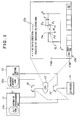
- Fig. 1 is a block diagram of an NC apparatus having an automatic programming function for realizing the method of the present invention.
- Numeral 11 denotes an automatic programming unit, 12 an NC control unit, 13 a graphic display unit (CRT) 14 a keyboard, and 15, 16 changeover units.
- the changeover units 15, 16 are illustrated as being switches for the sake of the description. In actuality, however, changeover is effected by software processing.
- the automatic programming unit 11 and NC control unit 12 are of microcomputer construction and incorporate an internal processor, a control program memory (ROM) and a RAM.
- the graphic display unit 13 and keyboard 14 are integrated into a single unit, as shown in Fig. 2, which is usually referred to as a CRT/MDI unit.
- the display screen is divided into a dialog display area 13a and a soft key area 13b.
- Keys 13c, 13c (see Fig. 2)... are provided to correspond to the soft key area. Pressing one of the keys enables the corresponding function displayed in the soft key area to be inputted.
- the keyboard 14 has an NC mode/automatic programming mode selection key 14a and a key group 14b, which includes keys serving as both arrow and numeric keys, as well as-a-C key and R key.
- Numeral 14c denotes an input key.
- a first machining method in which a tool TL is fed a predetermined amount d in a center direction of a blank to cut into the blank, after which the tool is fed an amount W corresponding to groove width longitudinally of the blank to perform grooving
- a second machining method as shown in Fig. 8(b), in which the tool TL is fed predetermined increments d in the center direction of the blank to perform machining down to groove depth, after which the tool is raised to perform grooving.
- Based on tool data for the tool used it is decided automatically in accordance with which of these machining methods grooving is to be performed.
- the tool used in grooving has the shape shown in Fig. 9.
- the cutter angle AC and nose angle AN are both set to zero.
- the cutter angle AC and nose angle AN are both set to values other than zero (non-zero values).
- a tooling file TLF is created in which tool number and tool shape data (cutter angle and nose angle) are made to correspond to a tool management number, and the tooling file TLF is registered in a RAM lla of the automatic programming unit 11.
- the operator operates the key 14a (Fig. 2) on the keyboard 14 to cause the changeover units 15, 16 to devote the graphic display unit 13 and keyboard 14 to the automatic programming unit 11. Thereafter, in accordance with the programming function of the automatic programming unit 11, processing up to the sixth step is executed in dilog fashion in a manner similar to the flow of the conventional method shown in Fig. 12. If a soft key "NEXT PAGE" is pressed in the sixth step, a part profile input processing routine is started to display the part profile input screen and make possible a part profile input (see Fig. 3).
- a part profile which contains a groove shape is entered by operating the arrow keys (tl ⁇ , ⁇ , ⁇ , etc.) and groove key (G key) provided on the keyboard.
- arrow keys tilt ⁇ , ⁇ , ⁇ , etc.
- G key groove key
- a prompt regarding the dimensions of the element is displayed. Therefore, when dimensions taken from a design drawing are entered in response to the prompt, a symbol PFS of the figure element and a graphic image PFG of the figure element of the figure element are displayed on the display screen.
- a groove width dimension wt and a groove depth dimension dt are entered in response to dimension prompts after the grooving key (G key) is pressed.
- a tool selection screen (Fig. 5) is displayed to make input of tool number possible (the tenth step in the flowchart of Fig. 12).
- the operator decides the tool upon taking into consideration the shape of the groove to be machined, and enters the tool management number of this tool.
- the operator decides the tool upon considering whether grooving is performed by repeating the first machining method [Figs. 8(a), (c)] or the second machining method [Fig. 8(b)], and then enters the tool management number.
- an arrangement can be adopted in which the tool for grooving can be decided automatically from the tooling file registered beforehand in the RAM of the automatic programming unit 11.
- the automatic programming unit 11 When entry of the tool management number or automatic decision processing end and the soft key "NEXT PAGE" is pressed, the automatic programming unit 11 reads the tool shape data of this tool management number out of the tooling file TFL and displays it on the CRT 13. Thereafter, when the soft key "NEXT PAGE" is pressed again, the automatic programming unit 11 displays the cutting condition input screen (Fig. 6) on the CRT, whereby entry of the cutting condition data for grooving becomes possible (llth step in the flowchart of Fig. 12).
- the automatic programming unit 11 displays a dialog screen (Fig. 7) for cutting area input on the CRT 13, whereby it becomes possible to enter starting- and end points of the cutting area (13th step of the flowchart of Fig. 12).
- the operator enters the coordinates of the starting point P and end point P of the groove shape.
- the automatic programming unit 11 decides a tool path for each entered machining process.
- the tool path for grooving is decided in a manner which will now be described with reference to the flowchart of Fig. 11.
- the automatic programming unit 11 goes to the tooling file TLF to read out the tool shape data of the grooving tool corresponding to the tool management number entered or automatically decided (step 101), and checks to see whether the cutter angle AC and nose angle AN contained in the tool data are both zero (step 102).
- the tool path is one in which the tool is fed a predetermined amount d in the direction of the center of the blank from the starting point P [see Fig. 8(a)] to cut into the blank, after which grooving is carried out be feeding the tool longitudinally of the blank by the amount W corresponding to groove width, wherein if machining cannot be performed to the depth dimension dt of the groove by the single predetermined feed amount d, the operation is split into a number of parts, as shown in Fig. 8(c), to feed the tool to the deepest portion of the groove to execute grooving.
- the tool path is one in which cut-in of the predetermined amount d from starting point P [Fig. 8(b)] to groove bottom GB and withdrawal by the relief amount u are repeated, the tool is raised temporarily after the groove bottom GB is reached, the tool is subsequently shifted in the groove width direction by the amount W corresponding to the tool width, and the foregoing operation is repeated until machining over the entire groove width ends.
- the automatic programming unit 11 creates an NC program that will move the tool along the tool path to perform grooving, and causes the tool path to be displayed on the CRT screen, after which the automatic programming processing is terminated (step 105).
- a first machining method in which a tool is fed a predetermined amount in a center direction of a blank to cut into the blank, after which the tool is fed an amount corresponding to groove width longitudinally of the blank to perform grooving
- a second machining method in which the tool is fed in the center direction of the blank to perform machining down to groove depth, after which the tool is raised to perform grooving, and the arrangement is such that a grooving tool path is created based on the machining method, which is selected in dependence upon the tool data indicative of the grooving tool.
Landscapes
- Physics & Mathematics (AREA)
- Engineering & Computer Science (AREA)
- Geometry (AREA)
- Human Computer Interaction (AREA)
- Manufacturing & Machinery (AREA)
- General Physics & Mathematics (AREA)
- Automation & Control Theory (AREA)
- Numerical Control (AREA)
- Milling, Broaching, Filing, Reaming, And Others (AREA)
Abstract
Description
- This invention relates to an automatic programming method and, more particularly, to an automatic programming method which creates an NC program for machining a part having a groove shape that is wide and deep.
- An automatic programming system is available in which a dialog display and a function key (soft key) display are each presented in accordance with each step of a plurality of data input steps, a function key (soft key) conforming to a specific function and appearing on the function key display is pressed to thereby execute processing corresponding to the function, and an NC program for turning is prepared using data inputted while referring to the dialog display.
- An automatic programming system of this kind, which will be described with reference to Fig. 12, successively displays predetermined message images (the dialog display) on a display screen in accordance with the following steps:
- (1) a first step of selecting execution of "AUTOMATIC PROGRAMMING";
- (2) a second step of selecting data to be inputted (a step to be executed next);
- (3) a third step of selecting the material of a blank;
- (4) a fourth step of setting surface roughness;
- (5) a fifth step of selecting a drawing format;
- (6) a sixth step of inputting the blank profile and the dimensions thereof;
- (7) a seventh step of inputting a part profile and the dimensions thereof;
- (8) an eighth step of inputting the machining reference point and turret position;
- (9) a ninth step of selecting a machining process;
- (10) a tenth step of selecting a tool and inputting tool data;
- (11) an eleventh step of deciding machining conditions;
- (12) a twelfth step of inputting cutting direction;
- (13) a thirteenth step of inputting cutting limits;
- (14) a fourteenth step of inputting whether or not an area is to be cut by the same tool; and
- (15) a fifteenth step of computing a tool path (i.e. of preparing NC data).
- An operator responds to the messages by entering the necessary data from a keyboard. Finally, an NC program (NC data) for turning is created using all of the entered data.
- Accordingly, when a slot shape is entered at the part profile input step (seventh step) and data for machining the slot are entered at the machining processing input step (ninth step), an NC program of a tool path (P ↦ P1 ↦ Pe) for machining a slot SLT from a starting point P to an end point Pe shown in Fig. 13(a), by way of example, is created at the 15th step of computing a tool path (NC program creation).
- There are cases where a slot SLT having a great width as shown in Fig. 13(b) is machined. In such cases, the conventional automatic programming method is such that, after cutting is performed over a cutting depth d from the starting point P to the point P1, a tool TL is raised to the point Ps in rapid-traverse, the tool is then fed longitudinally of the blank by an amount w corresponding to tool width and the same machining is performed from a point P2, after which the foregoing is repeated up to the end point Pe. Thus, a tool path is decided in such a manner that the foregoing grooving will take place. -When machining is thus performed down to the deepest part of a slot by the tool width according to the conventional method, the tool TL is raised to the outside of the slot SLT and is shifted by the amount of the tool width, after which a neighboring portion is machined.
- Consequently, when the slot SLT to be machined has a large width and depth, a long period of time is needed for cutting and the actions for raising the tool out of the slot increase in number, as a result of which machining time increases correspondingly.
- Accordingly, an object of the present invention is to provide an automatic programming method through which a tool path can be decided that will shorten grooving time.
- An automatic programming method according to the present invention is characterized by providing a first machining method in which a tool is fed a predetermined amount in a center direction of a blank to cut into the blank, after which the tool is fed an amount corresponding to groove width longitudinally of the blank to perform grooving, providing a second machining method in which the tool is fed in the center direction of the blank to perform machining down to groove depth, after which the tool is raised to perform grooving, deciding, based on tool data for the tool used in grooving, whether to perform grooving down to a designated groove depth by repeating the first machining method or perform grooving to a designated groove width by repeating the second machining method, creating a grooving tool path based on the machining method decided, and creating NC data for moving the tool along the tool path.
-
- Fig. 1 is a block diagram of an NC apparatus having an automatic programming function for realizing the method of the present invention;
- Fig. 2 is an external view of a CRT/MDI unit in the NC apparatus;
- Fig. 3 is a dialog screen for inputting a part profile;
- Fig. 4 is a dialog screen for selecting a machining process;
- Fig. 5 is a dialog screen for selecting a tool;
- Fig. 6 is a dialog screen for inputting cutting conditions;
- Fig. 7 is a dialog screen for inputting a cutting area;
- Fig. 8 shows an example of a tool path according to the present invention;
- Fig. 9 is a view for describing tool data;
- Fig. 10 is a view for describing cutting condition data;
- Fig. 11 is a flowchart of processing according to the invention; and
- Figs. 12 and 13 are views for-describing an example of the prior art.
- Fig. 1 is a block diagram of an NC apparatus having an automatic programming function for realizing the method of the present invention.
- Numeral 11 denotes an automatic programming unit, 12 an NC control unit, 13 a graphic display unit (CRT) 14 a keyboard, and 15, 16 changeover units. The
changeover units - The
automatic programming unit 11 andNC control unit 12 are of microcomputer construction and incorporate an internal processor, a control program memory (ROM) and a RAM. - The
graphic display unit 13 andkeyboard 14 are integrated into a single unit, as shown in Fig. 2, which is usually referred to as a CRT/MDI unit. As shown in Fig. 1, the display screen is divided into adialog display area 13a and asoft key area 13b. Keys 13c, 13c (see Fig. 2)... are provided to correspond to the soft key area. Pressing one of the keys enables the corresponding function displayed in the soft key area to be inputted. Thekeyboard 14 has an NC mode/automatic programming mode selection key 14a and a key group 14b, which includes keys serving as both arrow and numeric keys, as well as-a-C key and R key. Numeral 14c denotes an input key. - Automatic programming processing of the invention will now be described in accordance with the dialog screens of Figs. 3 through 7.
- As shown in Figs. 8(a), (c), there is a first machining method in which a tool TL is fed a predetermined amount d in a center direction of a blank to cut into the blank, after which the tool is fed an amount W corresponding to groove width longitudinally of the blank to perform grooving, and a second machining method, as shown in Fig. 8(b), in which the tool TL is fed predetermined increments d in the center direction of the blank to perform machining down to groove depth, after which the tool is raised to perform grooving. Based on tool data for the tool used, it is decided automatically in accordance with which of these machining methods grooving is to be performed.
- More specifically, the tool used in grooving has the shape shown in Fig. 9. With regard to the tool which performs grooving by repeating the first machining method, the cutter angle AC and nose angle AN are both set to zero. As for the tool which performs grooving by repeating the second machining method, the cutter angle AC and nose angle AN are both set to values other than zero (non-zero values). When the grooving tool has been decided, a check is made to see whether the cutter angle AC and nose angle AN of the tool are both zero. When AC = 0, AN-= 0 hold, the tool path is decided based on the first machining method. When
AC F 0,AN # 0 hold, the tool path is decided based on the second machining method. - A tooling file TLF is created in which tool number and tool shape data (cutter angle and nose angle) are made to correspond to a tool management number, and the tooling file TLF is registered in a RAM lla of the
automatic programming unit 11. - The operator operates the key 14a (Fig. 2) on the
keyboard 14 to cause thechangeover units graphic display unit 13 andkeyboard 14 to theautomatic programming unit 11. Thereafter, in accordance with the programming function of theautomatic programming unit 11, processing up to the sixth step is executed in dilog fashion in a manner similar to the flow of the conventional method shown in Fig. 12. If a soft key "NEXT PAGE" is pressed in the sixth step, a part profile input processing routine is started to display the part profile input screen and make possible a part profile input (see Fig. 3). In response to a prompt (ES = ) regarding a part profile element displayed on the display screen, a part profile which contains a groove shape is entered by operating the arrow keys (tl ↦, ↓, ←, etc.) and groove key (G key) provided on the keyboard. Whenever one part profile element is entered using an arrow key, a prompt regarding the dimensions of the element is displayed. Therefore, when dimensions taken from a design drawing are entered in response to the prompt, a symbol PFS of the figure element and a graphic image PFG of the figure element of the figure element are displayed on the display screen. In this example, a groove width dimension wt and a groove depth dimension dt are entered in response to dimension prompts after the grooving key (G key) is pressed. - Thereafter, an operation similar to that of the prior art is performed in accordance with the flowchart of Fig. 12. Then, when the process "9. GROOVING OR CORNERING" is selected by a prescribed operation from the dialog screen shown in Fig. 4 in the machining definition of the ninth step, a tool selection screen (Fig. 5) is displayed to make input of tool number possible (the tenth step in the flowchart of Fig. 12). Here the operator decides the tool upon taking into consideration the shape of the groove to be machined, and enters the tool management number of this tool. In other words, the operator decides the tool upon considering whether grooving is performed by repeating the first machining method [Figs. 8(a), (c)] or the second machining method [Fig. 8(b)], and then enters the tool management number. It should be noted that an arrangement can be adopted in which the tool for grooving can be decided automatically from the tooling file registered beforehand in the RAM of the
automatic programming unit 11. - When entry of the tool management number or automatic decision processing end and the soft key "NEXT PAGE" is pressed, the
automatic programming unit 11 reads the tool shape data of this tool management number out of the tooling file TFL and displays it on theCRT 13. Thereafter, when the soft key "NEXT PAGE" is pressed again, theautomatic programming unit 11 displays the cutting condition input screen (Fig. 6) on the CRT, whereby entry of the cutting condition data for grooving becomes possible (llth step in the flowchart of Fig. 12). Pecking yes/no (PE = ) on the cutting condition input screen refers to a machining method in which cutting is performed over a number of cycles while the tool is raised a relief amount u, this being carried out in a case where cutting cannot be performed down to the deepest part of a groove with a single depth of cut d, as in the case of a deep slot SLT shown in Fig. 8(b). In addition, clearance (C = ) and finishing tolerances (TW = , TB = ) are entered in order to specify a rough machining area AR (an area enclosed by the two-dot chain line), as shown in Fig. 10. - When the operator enters cutting conditions MS on the cutting condition input screen, as shown in Fig. 6, and then enters predetermined cutting direction data on a dialog screen for entering cutting direction, the
automatic programming unit 11 displays a dialog screen (Fig. 7) for cutting area input on theCRT 13, whereby it becomes possible to enter starting- and end points of the cutting area (13th step of the flowchart of Fig. 12). Here the operator enters the coordinates of the starting point P and end point P of the groove shape. - Thereafter, when the execute key is pressed after all data necessary for creation of the NC machining program have been entered, the
automatic programming unit 11 decides a tool path for each entered machining process. The tool path for grooving is decided in a manner which will now be described with reference to the flowchart of Fig. 11. - The
automatic programming unit 11 goes to the tooling file TLF to read out the tool shape data of the grooving tool corresponding to the tool management number entered or automatically decided (step 101), and checks to see whether the cutter angle AC and nose angle AN contained in the tool data are both zero (step 102). - If AC = 0, AN = 0 hold, then a tool path will be created along which grooving is performed repeatedly down to a designated groove depth on the basis of the first machining method (step 103). However, if
AC F 0, AN ≠ 0 hold, a tool path will be created along which grooving is performed repeatedly to a designated groove width on the basis of the second machining method (step 104). - By way of example, if AC = 0, AN = 0 hold, the tool path is one in which the tool is fed a predetermined amount d in the direction of the center of the blank from the starting point P [see Fig. 8(a)] to cut into the blank, after which grooving is carried out be feeding the tool longitudinally of the blank by the amount W corresponding to groove width, wherein if machining cannot be performed to the depth dimension dt of the groove by the single predetermined feed amount d, the operation is split into a number of parts, as shown in Fig. 8(c), to feed the tool to the deepest portion of the groove to execute grooving.
- On the other hand, if
AC F 0, AN ≠ 0 hold, the tool path is one in which cut-in of the predetermined amount d from starting point P [Fig. 8(b)] to groove bottom GB and withdrawal by the relief amount u are repeated, the tool is raised temporarily after the groove bottom GB is reached, the tool is subsequently shifted in the groove width direction by the amount W corresponding to the tool width, and the foregoing operation is repeated until machining over the entire groove width ends. - When the tool path has been decided by virtue of the following, the
automatic programming unit 11 creates an NC program that will move the tool along the tool path to perform grooving, and causes the tool path to be displayed on the CRT screen, after which the automatic programming processing is terminated (step 105). - In the foregoing, the description is based on the assumption that the tooling file has-been registered. However, in a case where no tooling file exists, it will be necessary to enter the tool shape data one item at a time. In such case, grooving will be carried out in accordance with the first machining method [Figs. 8(a), (c)] if the cutter angle AC and tool nose angle AN in the entered tool shape data are such that AC = AN = 0 holds.
- Further, in the foregoing description, it is decided to perform grooving in accordance with the first machining method or the second machining method depending upon whether the cutter angle AC and nose angle AN are both zero. However, an arrangement can be adopted in which other tool shape data are made zero or non-zero depending upon the machining method, or in which data indicating that grooving is to be carried out in accordance with the first or second machining method are separately provided and incorporated in the tool data.
- Thus, in accordance with the present invention, there are provided a first machining method in which a tool is fed a predetermined amount in a center direction of a blank to cut into the blank, after which the tool is fed an amount corresponding to groove width longitudinally of the blank to perform grooving, and a second machining method in which the tool is fed in the center direction of the blank to perform machining down to groove depth, after which the tool is raised to perform grooving, and the arrangement is such that a grooving tool path is created based on the machining method, which is selected in dependence upon the tool data indicative of the grooving tool. Thus, by selecting a tool conforming to the first or second machining method, it is possible to automatically decide a tool path capable of shortening grooving time. The invention is particularly effective when grooves are wide and deep.
Claims (4)
Applications Claiming Priority (3)
| Application Number | Priority Date | Filing Date | Title |
|---|---|---|---|
| JP3558/88 | 1988-01-11 | ||
| JP63003558A JPH01180009A (en) | 1988-01-11 | 1988-01-11 | Automatic programming system |
| PCT/JP1989/000025 WO1989006391A1 (en) | 1988-01-11 | 1989-01-11 | Automatic programming method |
Publications (3)
| Publication Number | Publication Date |
|---|---|
| EP0348533A1 true EP0348533A1 (en) | 1990-01-03 |
| EP0348533A4 EP0348533A4 (en) | 1993-08-04 |
| EP0348533B1 EP0348533B1 (en) | 1995-09-20 |
Family
ID=11560755
Family Applications (1)
| Application Number | Title | Priority Date | Filing Date |
|---|---|---|---|
| EP89901312A Expired - Lifetime EP0348533B1 (en) | 1988-01-11 | 1989-01-11 | Automatic programming method |
Country Status (5)
| Country | Link |
|---|---|
| US (1) | US5172327A (en) |
| EP (1) | EP0348533B1 (en) |
| JP (1) | JPH01180009A (en) |
| DE (1) | DE68924305T2 (en) |
| WO (1) | WO1989006391A1 (en) |
Cited By (1)
| Publication number | Priority date | Publication date | Assignee | Title |
|---|---|---|---|---|
| EP0543013A1 (en) * | 1991-06-07 | 1993-05-26 | Fanuc Ltd. | Method of preparing program for rough working |
Families Citing this family (13)
| Publication number | Priority date | Publication date | Assignee | Title |
|---|---|---|---|---|
| JPH084992B2 (en) * | 1989-12-13 | 1996-01-24 | オ−クマ株式会社 | Grooving method decision method in numerical control information creation function |
| JP2753364B2 (en) * | 1990-02-23 | 1998-05-20 | オークマ株式会社 | Numerical control information creation device |
| JPH04181403A (en) * | 1990-11-16 | 1992-06-29 | Fanuc Ltd | Interactive numerical controller |
| JP2901353B2 (en) * | 1990-12-28 | 1999-06-07 | オークマ株式会社 | Numerical control device with machining program editing function for numerically controlled machine tools |
| JP2773517B2 (en) * | 1992-02-27 | 1998-07-09 | 三菱電機株式会社 | Program display device |
| JPH05346815A (en) * | 1992-06-15 | 1993-12-27 | Okuma Mach Works Ltd | Automatic preparing method for groove machining information |
| JP3231027B2 (en) * | 1999-09-10 | 2001-11-19 | 義昭 垣野 | Numerical control device for NC machine tools |
| JP4592919B2 (en) * | 2000-10-26 | 2010-12-08 | シチズンホールディングス株式会社 | Automatic programming method and automatic programming apparatus |
| CN1241079C (en) | 2000-10-26 | 2006-02-08 | 西铁城时计株式会社 | Method and device for automatically preparing processing program |
| JP4657436B2 (en) * | 2000-10-26 | 2011-03-23 | シチズンホールディングス株式会社 | Automatic programming method and automatic programming apparatus |
| KR100461789B1 (en) * | 2002-03-25 | 2004-12-14 | 학교법인 포항공과대학교 | Method for performing delta volume decomposition and process planning in a turning step-nc system |
| DE102006009276C5 (en) * | 2006-03-01 | 2009-09-10 | Felsomat Gmbh & Co. Kg | Method for producing rotationally symmetrical surfaces on a workpiece and workpiece with a rotationally symmetrical surface |
| CN113064592A (en) * | 2021-03-31 | 2021-07-02 | 新代科技(苏州)有限公司 | Graph import programming method and system for grooving machine |
Citations (1)
| Publication number | Priority date | Publication date | Assignee | Title |
|---|---|---|---|---|
| EP0154028A2 (en) * | 1983-12-23 | 1985-09-11 | Mitsubishi Denki Kabushiki Kaisha | Working method in numerical control machine |
Family Cites Families (10)
| Publication number | Priority date | Publication date | Assignee | Title |
|---|---|---|---|---|
| US3685022A (en) * | 1970-07-27 | 1972-08-15 | Rohr Corp | Numerical control machining apparatus programmed for families of cutter sizes |
| JPS5890439A (en) * | 1981-11-25 | 1983-05-30 | Yamazaki Mazak Corp | Control method for milling process |
| JPS58120447A (en) * | 1981-12-30 | 1983-07-18 | Yamazaki Mazak Corp | Control method of grooving work in numerically controlled lathe |
| JPS5981707A (en) * | 1982-10-30 | 1984-05-11 | Fanuc Ltd | Automatic producing method of nc data |
| JPS60126710A (en) * | 1983-12-14 | 1985-07-06 | Fanuc Ltd | Method for determining working process in automatic programming |
| JPH0611458B2 (en) * | 1985-06-27 | 1994-02-16 | ファナック株式会社 | Tool shape display device |
| JPS62137609A (en) * | 1985-12-10 | 1987-06-20 | Fanuc Ltd | Nc data generation method |
| JPS62208858A (en) * | 1986-03-07 | 1987-09-14 | Hitachi Seiki Co Ltd | Part programming device in machining center |
| EP0311703B1 (en) * | 1987-10-14 | 1991-12-18 | TRAUB Aktiengesellschaft | Method for controlling a machine tool |
| JPH01222304A (en) * | 1988-03-01 | 1989-09-05 | Fanuc Ltd | Nc sentence generation system |
-
1988
- 1988-01-11 JP JP63003558A patent/JPH01180009A/en active Pending
-
1989
- 1989-01-11 WO PCT/JP1989/000025 patent/WO1989006391A1/en active IP Right Grant
- 1989-01-11 DE DE68924305T patent/DE68924305T2/en not_active Expired - Fee Related
- 1989-01-11 US US07/415,305 patent/US5172327A/en not_active Expired - Fee Related
- 1989-01-11 EP EP89901312A patent/EP0348533B1/en not_active Expired - Lifetime
Patent Citations (1)
| Publication number | Priority date | Publication date | Assignee | Title |
|---|---|---|---|---|
| EP0154028A2 (en) * | 1983-12-23 | 1985-09-11 | Mitsubishi Denki Kabushiki Kaisha | Working method in numerical control machine |
Non-Patent Citations (2)
| Title |
|---|
| PATENT ABSTRACTS OF JAPAN vol. 9, no. 286 (M-429)13 November 1985 & JP-A-60 127 946 ( FANUC ) 8 July 1985 * |
| See also references of WO8906391A1 * |
Cited By (2)
| Publication number | Priority date | Publication date | Assignee | Title |
|---|---|---|---|---|
| EP0543013A1 (en) * | 1991-06-07 | 1993-05-26 | Fanuc Ltd. | Method of preparing program for rough working |
| EP0543013A4 (en) * | 1991-06-07 | 1993-08-11 | Fanuc Ltd. | Method of preparing program for rough working |
Also Published As
| Publication number | Publication date |
|---|---|
| JPH01180009A (en) | 1989-07-18 |
| DE68924305T2 (en) | 1996-02-29 |
| EP0348533A4 (en) | 1993-08-04 |
| US5172327A (en) | 1992-12-15 |
| EP0348533B1 (en) | 1995-09-20 |
| DE68924305D1 (en) | 1995-10-26 |
| WO1989006391A1 (en) | 1989-07-13 |
Similar Documents
| Publication | Publication Date | Title |
|---|---|---|
| EP0348533B1 (en) | Automatic programming method | |
| US4926311A (en) | Part profile input method | |
| EP0078856B2 (en) | Numerical control device | |
| US5177689A (en) | Cad/cam apparatus for enhancing operator entry of machining attributes and geometric shapes | |
| EP0177164B1 (en) | Method and apparatus for producing numerical control programmes | |
| EP0044192B2 (en) | A method for preparing numerical control information | |
| EP0249639B1 (en) | Method of preparing nc data | |
| US5798928A (en) | Tool specifying method and apparatus for an NC automatic programming system | |
| EP0265525B1 (en) | Method of preparing nc program for four-spindle lathe | |
| EP3733343B1 (en) | Tool selection device, method, and program, and nc program creation system | |
| EP0247204B1 (en) | Interactive programming device | |
| EP0348522B1 (en) | Method of inputting part profile | |
| EP0309589B1 (en) | Method of inputting profile information on product | |
| EP0229848A1 (en) | System for automatically drawing profile of tool | |
| US5099432A (en) | Method for determining machining process in numerical control information generating function | |
| EP0137047A1 (en) | Method of determining three-dimensional tool path | |
| EP0425674A1 (en) | Automatic tool selecting system | |
| US5029068A (en) | NC data creation method | |
| US5163171A (en) | Method of setting nc data output format | |
| EP0519075A1 (en) | Method of forming nc data | |
| EP0348518A1 (en) | Graphics definition method in automatic programming | |
| EP0148947A1 (en) | Data input method | |
| JPH0685130B2 (en) | Processing area division processing device in automatic processing machine | |
| EP0500936A1 (en) | Method of depicting numeric control data for machining polyhedron | |
| JPS6049403A (en) | Output control system of file |
Legal Events
| Date | Code | Title | Description |
|---|---|---|---|
| PUAI | Public reference made under article 153(3) epc to a published international application that has entered the european phase |
Free format text: ORIGINAL CODE: 0009012 |
|
| 17P | Request for examination filed |
Effective date: 19890921 |
|
| AK | Designated contracting states |
Kind code of ref document: A1 Designated state(s): DE FR GB |
|
| RHK1 | Main classification (correction) |
Ipc: G05B 19/405 |
|
| A4 | Supplementary search report drawn up and despatched |
Effective date: 19930615 |
|
| AK | Designated contracting states |
Kind code of ref document: A4 Designated state(s): DE FR GB |
|
| 17Q | First examination report despatched |
Effective date: 19950127 |
|
| GRAA | (expected) grant |
Free format text: ORIGINAL CODE: 0009210 |
|
| AK | Designated contracting states |
Kind code of ref document: B1 Designated state(s): DE FR GB |
|
| PG25 | Lapsed in a contracting state [announced via postgrant information from national office to epo] |
Ref country code: FR Effective date: 19950920 |
|
| REF | Corresponds to: |
Ref document number: 68924305 Country of ref document: DE Date of ref document: 19951026 |
|
| PG25 | Lapsed in a contracting state [announced via postgrant information from national office to epo] |
Ref country code: GB Effective date: 19960111 |
|
| PGFP | Annual fee paid to national office [announced via postgrant information from national office to epo] |
Ref country code: DE Payment date: 19960115 Year of fee payment: 8 |
|
| EN | Fr: translation not filed | ||
| PLBE | No opposition filed within time limit |
Free format text: ORIGINAL CODE: 0009261 |
|
| STAA | Information on the status of an ep patent application or granted ep patent |
Free format text: STATUS: NO OPPOSITION FILED WITHIN TIME LIMIT |
|
| GBPC | Gb: european patent ceased through non-payment of renewal fee |
Effective date: 19960111 |
|
| 26N | No opposition filed | ||
| PG25 | Lapsed in a contracting state [announced via postgrant information from national office to epo] |
Ref country code: DE Effective date: 19971001 |