EP0348359B1 - Dusche mit Drehwähler zur Erzeugung von verschiedenen Wasserstrahlen - Google Patents
Dusche mit Drehwähler zur Erzeugung von verschiedenen Wasserstrahlen Download PDFInfo
- Publication number
- EP0348359B1 EP0348359B1 EP89830240A EP89830240A EP0348359B1 EP 0348359 B1 EP0348359 B1 EP 0348359B1 EP 89830240 A EP89830240 A EP 89830240A EP 89830240 A EP89830240 A EP 89830240A EP 0348359 B1 EP0348359 B1 EP 0348359B1
- Authority
- EP
- European Patent Office
- Prior art keywords
- nozzle
- hole
- shower
- water
- passage
- Prior art date
- Legal status (The legal status is an assumption and is not a legal conclusion. Google has not performed a legal analysis and makes no representation as to the accuracy of the status listed.)
- Expired - Lifetime
Links
Images




Classifications
-
- B—PERFORMING OPERATIONS; TRANSPORTING
- B05—SPRAYING OR ATOMISING IN GENERAL; APPLYING FLUENT MATERIALS TO SURFACES, IN GENERAL
- B05B—SPRAYING APPARATUS; ATOMISING APPARATUS; NOZZLES
- B05B1/00—Nozzles, spray heads or other outlets, with or without auxiliary devices such as valves, heating means
- B05B1/14—Nozzles, spray heads or other outlets, with or without auxiliary devices such as valves, heating means with multiple outlet openings; with strainers in or outside the outlet opening
- B05B1/16—Nozzles, spray heads or other outlets, with or without auxiliary devices such as valves, heating means with multiple outlet openings; with strainers in or outside the outlet opening having selectively- effective outlets
- B05B1/1627—Nozzles, spray heads or other outlets, with or without auxiliary devices such as valves, heating means with multiple outlet openings; with strainers in or outside the outlet opening having selectively- effective outlets with a selecting mechanism comprising a gate valve, a sliding valve or a cock
- B05B1/1636—Nozzles, spray heads or other outlets, with or without auxiliary devices such as valves, heating means with multiple outlet openings; with strainers in or outside the outlet opening having selectively- effective outlets with a selecting mechanism comprising a gate valve, a sliding valve or a cock by relative rotative movement of the valve elements
-
- B—PERFORMING OPERATIONS; TRANSPORTING
- B05—SPRAYING OR ATOMISING IN GENERAL; APPLYING FLUENT MATERIALS TO SURFACES, IN GENERAL
- B05B—SPRAYING APPARATUS; ATOMISING APPARATUS; NOZZLES
- B05B1/00—Nozzles, spray heads or other outlets, with or without auxiliary devices such as valves, heating means
- B05B1/02—Nozzles, spray heads or other outlets, with or without auxiliary devices such as valves, heating means designed to produce a jet, spray, or other discharge of particular shape or nature, e.g. in single drops, or having an outlet of particular shape
- B05B1/08—Nozzles, spray heads or other outlets, with or without auxiliary devices such as valves, heating means designed to produce a jet, spray, or other discharge of particular shape or nature, e.g. in single drops, or having an outlet of particular shape of pulsating nature, e.g. delivering liquid in successive separate quantities
- B05B1/083—Nozzles, spray heads or other outlets, with or without auxiliary devices such as valves, heating means designed to produce a jet, spray, or other discharge of particular shape or nature, e.g. in single drops, or having an outlet of particular shape of pulsating nature, e.g. delivering liquid in successive separate quantities the pulsating mechanism comprising movable parts
- B05B1/085—Nozzles, spray heads or other outlets, with or without auxiliary devices such as valves, heating means designed to produce a jet, spray, or other discharge of particular shape or nature, e.g. in single drops, or having an outlet of particular shape of pulsating nature, e.g. delivering liquid in successive separate quantities the pulsating mechanism comprising movable parts rotated by the liquid or other fluent material discharged, e.g. liquid rotated turbines
-
- B—PERFORMING OPERATIONS; TRANSPORTING
- B05—SPRAYING OR ATOMISING IN GENERAL; APPLYING FLUENT MATERIALS TO SURFACES, IN GENERAL
- B05B—SPRAYING APPARATUS; ATOMISING APPARATUS; NOZZLES
- B05B1/00—Nozzles, spray heads or other outlets, with or without auxiliary devices such as valves, heating means
- B05B1/14—Nozzles, spray heads or other outlets, with or without auxiliary devices such as valves, heating means with multiple outlet openings; with strainers in or outside the outlet opening
- B05B1/18—Roses; Shower heads
Definitions
- the invention relates to a shower with a rotating watering can and structured to deliver water jets having different shapes.
- showers of this type are described, for example, by documents US-A-4,629,125 e DE-A-37 06,320. They are composed of a body delimiting a pipe, one end of which is connected to a pipe of , while its other end has an opening, a head for the selective flow of at least three different forms of water jets through as many concentric rows of holes located at the end respectively of a first annular passage, a second annular passage and a third annular passage provided in the head and intended to receive the water supplied by the opening of the body.
- showers of the known type are all relatively complex, laborious and expensive, since they are composed of many component parts.
- the object of the invention is to provide an improved shower, capable of delivering three different forms of water jets, which is formed from a limited number of parts that are easy to produce, quickly assembled and of high reliability.
- the shower according to the invention conforms to the characterizing part of claim 1.
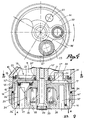
- the shower comprises a tubular body 10 defining a longitudinal pipe 11 which on one side is connected to a water supply pipe 12, while on the other side it has an opening 13 communicating with a head 14 for the flow controlled by several water jets according to arrows A, B and C respectively.
- the shower head 14 is substantially composed of three concentric parts, that is to say: a distributor 15, a front diffuser 16 and an intermediate diverter 17.
- the dispenser 15 is presented as an inverted glass with a peripheral notch 18 mating, by rotation, with the edge 13 ′ of the opening of the body 10 with the interposition of a gasket 19.
- the distributor 15 has a transverse wall or bottom 20 provided with a central hole 20 ′ which receives, with the interposition of a gasket 21 ′, a guide pin 10 ′ secured to the body 10, at the center of the opening 13.
- the transverse wall of the distributor 15 closes the opening 13, but it is provided with an eccentric hole 22 for the passage of water from the pipe 11 inside the head 14.
- a plug 23 can be moved by turning the distributor 15.
- the front diffuser 16 which in turn has the shape of a cup, mates, without being attached to it, with the side wall of the distributor 15 by means of its edge 16 ′ and with the interposition of a lining 24.
- a hub 25 is placed in a central position on the bottom of the diffuser, which is crossed, on three concentric circles, by a first row of holes 26 for the formation of a first jet of water A, of a second row of holes 27 for the second water jet B and a third row of holes 28 for a third water jet C.
- the central hub 25 is coaxial with the stud 10 ′ of the body 10 and a clamping screw 29 to be screwed in the stud is used to block the diffuser 16 and also leaving the intermediate deflector 17.
- the transverse wall of this dermier is parallel to the bottom of the distributor 15 and its central part 17 ′ is fixed to the hub 25 by means of a conical coupling 30 and inserted into the distributor 15. Starting from the three parts 15, 16 and 17 are coupled to the package and connected to the body 10 by means of the single screw 29.
- the intermediate deflector 17 has two outer and inner concentric walls 33, 34 which mate with one another and in a sealed manner to the base wall of the front diffuser and which are parallel, on one side, to the peripheral wall of the distributor. turning 15 and on the other side, to the central hub 25.
- the outer wall 33 defines, with the distributor, a first annular passage 36 communicating, above, directly with the space 31 of distribution and below with the first row of holes 26 of the diffuser.
- the hole 37 ′ is provided with a sealing ring 37 ⁇ .
- the inner wall 34 defines, with the central hub 25, a communicating chamber 38, superiorly, with a hole 38 ′ drilled in the transverse wall of the deflector in correspondence with the projection 32 and, inferiorly, with the third row of holes 28 of the diffuser.
- the inlet of the hole 38 ′ is provided with a sealing ring 38 ⁇ and in the chamber 38 a finned rotor or turbine 39 - known as such - acts as a rotary valve.
- the distributor 15 is turned to the position of which in FIGS. 5 and 6, while the hole 38 ′ for entering the chamber 38 with rotor or turbine 39 is still closed, the distribution hole 22 of the distributor 15 is aligned with the hole 37 ′ at the entrance to the second passage 37. Consequently, the water passes through the second row of holes 27 of the diffuser 16 with an aerated or foaming jet B, because the flow of water tends to suck l through the holes 26 and the first passage 36 (arrow D) and to mix with this air.
Landscapes
- Nozzles (AREA)
Claims (4)
- Dusche durch ein Gehäuse (10) gebildet, das eine Leitung (11) abgrenzt, deren ein Ende mit einer wasserleitung verbunden ist und das andere eine Öffnung (13) aufweist, durch einen Kopf (14) für die Wahlversorgung von mindestens drei verschiedenen Wasserstrahlen (A, B, C) durch ebensoviele konzentrische Reihen von Bohrungen (26, 27, 28), die an den Enden beziehungsweise eines ersten ringförmigen Übergangs, eines zweiten ringförmigen Übergangs und eines dritten ringförmigen Übergangs (36, 37, 38) angeordnet sind, die in dem Kopf (14) vorgesehen sind und das aus der Öffnung (13) des Gehäuses (10) herausfliessende Wasser bekommen,
gekennzeichnet dadurch, dass
der Kopf (14) eine Versorgungsvorrichtung (15) besitzt, die sich in der Öffnung (13) des Gehäuses (10) dreht und mit einer Klappe (20) versehen ist, die die Öffnung (13) grundsätzlich schliesst und eine erste Bohrung (22) für die Wahlversorgung des aus dieser Leitung (11) in die obengenannten Übergänge (36, 37, 38) fliessenden Wassers sowie eine Nase, die als Stopfen (23) gilt, aufweist, eine stationäre vordere Versorgungsvorrichtung (16), die am obengenannten Gehäuse befestigt und am Streukörper (15) peripherisch angekuppelt ist und mit drei Reihen von Bohrungen (26, 27, 28) zur Bildung des Wasserstrahles versehen ist, und einen stationären Abweiser (17), der zwischen der Versorgungsvorrichtung (15) und dem Streukörper (16) angeordnet ist, um mit ihnen den ersten, den zweiten und den dritten Übergang (36, 37, 38) abzugrenzen, die das Wasser zu den drei Reihen von Bohrungen (26, 27, 28) beziehungsweise zwischen der Versorgungsvorrichtung (15) und dem Abweiser (17) fördern, mit einer Nute (31), die das Hasser durch die erste Bohrung (22) der Versorgungsvorrichtung empfängt; der erste der obengenannten Übergänge (36) ist in ständiger verbindung mit der Nute (31), der zweite Übergang (37) mit der Nute (31) durch eine zweite Bohrung (37′), deren Auf/zu durch einen Stopfen (23) der Versorgungsvorrichtung (15) erfolgt, der dritte Übergang (38) weist eine dritte Bohrung (38′) auf, die mit der ersten versorgungsbohrung (22) oder mit dieser dritten durch die Innenfläche der Versorgungsvorrichtung geschlossenen Einlaufbohrung Ubereinstimmen soll, wenn die erste Versorgungsbohrung (22) von der dritten Einlaufbohrung (38′) des dritten Übergangs (38) entfernt wird. - Dusche nach Anspruch 1), dadurch gekennzeichnet, dass die Versorgungovorrichtung (15) dicht um einen Bolzen (10′) dreht, der sich einteilig mit dem Duschegehäuse, dem Streukörper (16) und dem Abweiser (17) dreht und koaxial zu dieser Versorgungsvorrichtung (15) ist, durch eine Zentralschraube (29) mit dem Bolzen (10) dicht gekuppelt und befestigt, mit einem Teil der Versorgungsvorrichtung (15), die auf dem Zwischenabweiser (17) liegt und am vorderen Streukörper (16) peripherisch angekuppelt ist.
- Dusche nach Ansprüchen 1) und 2), dadurch gekennzeichnet, dass der dritte Übergang (38) ein Drehventil (39) aufweist für den Durchfluss der Wasserstrahlen, die durch die Reihe von Bohrungen (28) gefördert werden, die diesem dritten Übergang (38) entspricht.
- Dusche nach einem der vorhergehenden Ansprüche, dadurch gekennzeichnet, dass die erste versorgungsbohrung (22) der Versorgungsvorrichtung (15) so positioniert werden kann, dass die gleichzeitige Versorgung einer ersten und zweiten Reihe von Bohrungen (26, 27) erfolgen kann.
Applications Claiming Priority (2)
| Application Number | Priority Date | Filing Date | Title |
|---|---|---|---|
| IT518688 | 1988-06-23 | ||
| IT8805186A IT8805186A0 (it) | 1988-06-23 | 1988-06-23 | Doccia con selettore rotante per erogare diversi getti d'acqua. |
Publications (3)
| Publication Number | Publication Date |
|---|---|
| EP0348359A2 EP0348359A2 (de) | 1989-12-27 |
| EP0348359A3 EP0348359A3 (en) | 1990-10-10 |
| EP0348359B1 true EP0348359B1 (de) | 1992-11-19 |
Family
ID=11119031
Family Applications (1)
| Application Number | Title | Priority Date | Filing Date |
|---|---|---|---|
| EP89830240A Expired - Lifetime EP0348359B1 (de) | 1988-06-23 | 1989-05-30 | Dusche mit Drehwähler zur Erzeugung von verschiedenen Wasserstrahlen |
Country Status (4)
| Country | Link |
|---|---|
| EP (1) | EP0348359B1 (de) |
| DE (1) | DE68903537T2 (de) |
| ES (1) | ES2037469T3 (de) |
| IT (1) | IT8805186A0 (de) |
Cited By (7)
| Publication number | Priority date | Publication date | Assignee | Title |
|---|---|---|---|---|
| USD715398S1 (en) | 2013-03-16 | 2014-10-14 | Kohler Co. | Shower faceplate |
| USD715896S1 (en) | 2013-03-15 | 2014-10-21 | Kohler Co. | Shower faceplate |
| USD716415S1 (en) | 2013-03-15 | 2014-10-28 | Kohler Co. | Shower faceplate |
| USD719240S1 (en) | 2013-08-23 | 2014-12-09 | Kohler Co. | Shower device |
| USD740917S1 (en) | 2013-03-16 | 2015-10-13 | Kohler Co. | Shower faceplate for shower device |
| USD759197S1 (en) | 2012-03-12 | 2016-06-14 | Kohler Co. | Shower faceplate |
| US9468939B2 (en) | 2012-03-12 | 2016-10-18 | Kohler Co. | Faceplate for shower device |
Families Citing this family (13)
| Publication number | Priority date | Publication date | Assignee | Title |
|---|---|---|---|---|
| DE9005700U1 (de) * | 1990-05-19 | 1990-07-26 | Christophery Gmbh, 5860 Iserlohn | Brausekopf |
| DE4116930A1 (de) * | 1991-05-24 | 1992-11-26 | Grohe Armaturen Friedrich | Brausekopf |
| DE4116927A1 (de) * | 1991-05-24 | 1992-11-26 | Grohe Armaturen Friedrich | Brause |
| FR2683745B1 (fr) * | 1991-11-15 | 1995-04-14 | Valentin Finance Sa | Douchette a jets multiples. |
| ES2049153B1 (es) * | 1991-12-02 | 1996-12-01 | Lopez Gutierrez M Del Transito | Ducha perfeccionada con salida de agua regulable. |
| ES2064214B1 (es) * | 1992-08-20 | 1997-07-01 | Farina Soler Fernando | Cabezal de ducha con efecto de hidromasaje |
| FR2707528B1 (fr) * | 1993-07-16 | 1995-09-08 | Valentin Sa | Douchette à jets multiples. |
| IT1299132B1 (it) | 1998-01-16 | 2000-02-29 | Simone Fiorentino De | Dispositivo perfezionato per idromassaggio massaggio rilassante doccia maneggiabbile a mano o fissabile alla parte attrezzata o meno e/o alla |
| WO2009079883A1 (en) * | 2007-12-24 | 2009-07-02 | Ateck (Xiamen) Showers Co., Ltd. | A discharge switching device for a shower |
| DE102012020420B4 (de) * | 2012-10-18 | 2021-04-29 | Volkswagen Aktiengesellschaft | Verzweigungs- oder Zusammenführungselement für gasförmige Fluide |
| US9687859B2 (en) | 2012-11-16 | 2017-06-27 | Kohler Co. | Shower device |
| DE102016213489B3 (de) * | 2016-07-22 | 2017-11-09 | Hansgrohe Se | Brausenumschaltventil und Sanitärbrause |
| DE102021114029A1 (de) * | 2021-05-31 | 2022-12-01 | Grohe Ag | Vorrichtung zum Umstellen eines Strömungswegs einer Flüssigkeit einer Sanitärbrause |
Family Cites Families (2)
| Publication number | Priority date | Publication date | Assignee | Title |
|---|---|---|---|---|
| US4629125A (en) * | 1984-08-27 | 1986-12-16 | Fuyi Liu | Spray nozzle |
| IT8605219A0 (it) * | 1986-09-30 | 1986-09-30 | Chiari & Guerini Snc | Testa di doccia per l'erogazione selettiva di diversi getti d'acqua. |
-
1988
- 1988-06-23 IT IT8805186A patent/IT8805186A0/it unknown
-
1989
- 1989-05-30 DE DE8989830240T patent/DE68903537T2/de not_active Expired - Fee Related
- 1989-05-30 EP EP89830240A patent/EP0348359B1/de not_active Expired - Lifetime
- 1989-05-30 ES ES198989830240T patent/ES2037469T3/es not_active Expired - Lifetime
Cited By (19)
| Publication number | Priority date | Publication date | Assignee | Title |
|---|---|---|---|---|
| USD779038S1 (en) | 2012-03-12 | 2017-02-14 | Kohler Co. | Shower faceplate and shower device |
| USD759197S1 (en) | 2012-03-12 | 2016-06-14 | Kohler Co. | Shower faceplate |
| US9468939B2 (en) | 2012-03-12 | 2016-10-18 | Kohler Co. | Faceplate for shower device |
| USD771770S1 (en) | 2013-03-15 | 2016-11-15 | Kohler Co. | Shower device |
| USD715896S1 (en) | 2013-03-15 | 2014-10-21 | Kohler Co. | Shower faceplate |
| USD716415S1 (en) | 2013-03-15 | 2014-10-28 | Kohler Co. | Shower faceplate |
| USD779039S1 (en) | 2013-03-15 | 2017-02-14 | Kohler Co. | Shower faceplate and shower device |
| USD779042S1 (en) | 2013-03-15 | 2017-02-14 | Kohler Co. | Shower faceplate and shower device |
| USD779043S1 (en) | 2013-03-15 | 2017-02-14 | Kohler Co. | Shower faceplate and shower device |
| USD774162S1 (en) | 2013-03-15 | 2016-12-13 | Kohler Co. | Shower faceplate |
| USD776789S1 (en) | 2013-03-16 | 2017-01-17 | Kohler Co. | Shower faceplate |
| USD715398S1 (en) | 2013-03-16 | 2014-10-14 | Kohler Co. | Shower faceplate |
| USD776788S1 (en) | 2013-03-16 | 2017-01-17 | Kohler Co. | Shower faceplate |
| USD776790S1 (en) | 2013-03-16 | 2017-01-17 | Kohler Co. | Shower faceplate |
| USD754283S1 (en) | 2013-03-16 | 2016-04-19 | Kohler Co. | Shower faceplate |
| USD752712S1 (en) | 2013-03-16 | 2016-03-29 | Kohler Co. | Shower faceplate for shower device |
| USD740917S1 (en) | 2013-03-16 | 2015-10-13 | Kohler Co. | Shower faceplate for shower device |
| USD760347S1 (en) | 2013-08-23 | 2016-06-28 | Kohler Co. | Shower device |
| USD719240S1 (en) | 2013-08-23 | 2014-12-09 | Kohler Co. | Shower device |
Also Published As
| Publication number | Publication date |
|---|---|
| DE68903537T2 (de) | 1993-04-08 |
| ES2037469T3 (es) | 1993-06-16 |
| IT8805186A0 (it) | 1988-06-23 |
| EP0348359A3 (en) | 1990-10-10 |
| DE68903537D1 (de) | 1992-12-24 |
| EP0348359A2 (de) | 1989-12-27 |
Similar Documents
| Publication | Publication Date | Title |
|---|---|---|
| EP0348359A2 (de) | Dusche mit Drehwähler zur Erzeugung von verschiedenen Wasserstrahlen | |
| EP0555766B1 (de) | Zusatzgerät zum Bereiten von Cappuccino | |
| FR2618697A1 (fr) | Appareil pour augmenter l'energie de l'ecoulement de l'eau dans un gicleur de douche | |
| US5931080A (en) | Espresso coffee machine provided with a device for whipping milk | |
| FR2613638A3 (fr) | Pomme de douche reglable pour la projection de cinq jets differents | |
| FR2573289A1 (fr) | Casque integral muni d'un systeme de ventilation perfectionne | |
| FR2624765A1 (fr) | Tete et dispositif pour douche | |
| FR2671329A1 (fr) | Embout-poussoir a jets multiples et a fermeture. | |
| EP1563910A1 (de) | Flüssigkeitssprühpistole mit variabler Strahlbildung für den Gartenbau | |
| US6113009A (en) | Sprinkler head adjusting structure | |
| FR2683745A1 (fr) | Douchette a jets multiples. | |
| CH652803A5 (fr) | Injecteur de combustible et moteur a combustion interne equipe dudit injecteur. | |
| FR2627708A1 (fr) | Dispositif pour permettre l'emploi en toutes positions d'une valve de vaporisateur | |
| EP0947754B1 (de) | Impulsgesteuertes, elektromagnetisches Hydraulikventil | |
| JPH1071344A (ja) | 噴霧用ノズル構造体 | |
| FR2768353A1 (fr) | Pomme de douche laterale orientable, reglable et a fermeture pour cabines de douche et similaires | |
| JPH0543869Y2 (de) | ||
| JP2002225991A (ja) | 発泡飲料流出用のバルブ | |
| CH665347A5 (en) | Oral hygiene spray device - has spray head connectable to pressurised liq. supply, with selective control between multiple and single between multiple and single jets | |
| JPS6026861Y2 (ja) | フオ−マ−泡噴出器における安全装置 | |
| JPH033321Y2 (de) | ||
| JP3026739U (ja) | 散水用ノズル | |
| JPH0582432U (ja) | 気泡浴槽 | |
| CA1294652C (fr) | Dispositif de lavage a deux douches commande par selecteur | |
| FR2707528A1 (fr) | Douchette à jets multiples. |
Legal Events
| Date | Code | Title | Description |
|---|---|---|---|
| PUAI | Public reference made under article 153(3) epc to a published international application that has entered the european phase |
Free format text: ORIGINAL CODE: 0009012 |
|
| AK | Designated contracting states |
Kind code of ref document: A2 Designated state(s): DE ES FR GB IT |
|
| PUAL | Search report despatched |
Free format text: ORIGINAL CODE: 0009013 |
|
| AK | Designated contracting states |
Kind code of ref document: A3 Designated state(s): DE ES FR GB IT |
|
| 17P | Request for examination filed |
Effective date: 19901213 |
|
| 17Q | First examination report despatched |
Effective date: 19911206 |
|
| GRAA | (expected) grant |
Free format text: ORIGINAL CODE: 0009210 |
|
| ITF | It: translation for a ep patent filed | ||
| AK | Designated contracting states |
Kind code of ref document: B1 Designated state(s): DE ES FR GB IT |
|
| REF | Corresponds to: |
Ref document number: 68903537 Country of ref document: DE Date of ref document: 19921224 |
|
| GBT | Gb: translation of ep patent filed (gb section 77(6)(a)/1977) |
Effective date: 19930219 |
|
| PGFP | Annual fee paid to national office [announced via postgrant information from national office to epo] |
Ref country code: ES Payment date: 19930420 Year of fee payment: 5 |
|
| PGFP | Annual fee paid to national office [announced via postgrant information from national office to epo] |
Ref country code: DE Payment date: 19930421 Year of fee payment: 5 |
|
| PGFP | Annual fee paid to national office [announced via postgrant information from national office to epo] |
Ref country code: FR Payment date: 19930426 Year of fee payment: 5 |
|
| PG25 | Lapsed in a contracting state [announced via postgrant information from national office to epo] |
Ref country code: GB Effective date: 19930530 |
|
| REG | Reference to a national code |
Ref country code: ES Ref legal event code: FG2A Ref document number: 2037469 Country of ref document: ES Kind code of ref document: T3 |
|
| PLBE | No opposition filed within time limit |
Free format text: ORIGINAL CODE: 0009261 |
|
| STAA | Information on the status of an ep patent application or granted ep patent |
Free format text: STATUS: NO OPPOSITION FILED WITHIN TIME LIMIT |
|
| 26N | No opposition filed | ||
| GBPC | Gb: european patent ceased through non-payment of renewal fee |
Effective date: 19930530 |
|
| PG25 | Lapsed in a contracting state [announced via postgrant information from national office to epo] |
Ref country code: ES Free format text: LAPSE BECAUSE OF NON-PAYMENT OF DUE FEES Effective date: 19940531 |
|
| PG25 | Lapsed in a contracting state [announced via postgrant information from national office to epo] |
Ref country code: FR Effective date: 19950131 |
|
| PG25 | Lapsed in a contracting state [announced via postgrant information from national office to epo] |
Ref country code: DE Effective date: 19950201 |
|
| REG | Reference to a national code |
Ref country code: FR Ref legal event code: ST |
|
| REG | Reference to a national code |
Ref country code: ES Ref legal event code: FD2A Effective date: 19990201 |
|
| PG25 | Lapsed in a contracting state [announced via postgrant information from national office to epo] |
Ref country code: IT Free format text: LAPSE BECAUSE OF NON-PAYMENT OF DUE FEES;WARNING: LAPSES OF ITALIAN PATENTS WITH EFFECTIVE DATE BEFORE 2007 MAY HAVE OCCURRED AT ANY TIME BEFORE 2007. THE CORRECT EFFECTIVE DATE MAY BE DIFFERENT FROM THE ONE RECORDED. Effective date: 20050530 |