EP0348336A2 - Trommel zum Falten von Gürtellagen eines Radialreifens - Google Patents
Trommel zum Falten von Gürtellagen eines Radialreifens Download PDFInfo
- Publication number
- EP0348336A2 EP0348336A2 EP89630105A EP89630105A EP0348336A2 EP 0348336 A2 EP0348336 A2 EP 0348336A2 EP 89630105 A EP89630105 A EP 89630105A EP 89630105 A EP89630105 A EP 89630105A EP 0348336 A2 EP0348336 A2 EP 0348336A2
- Authority
- EP
- European Patent Office
- Prior art keywords
- drum
- segments
- hub assemblies
- central
- central hub
- Prior art date
- Legal status (The legal status is an assumption and is not a legal conclusion. Google has not performed a legal analysis and makes no representation as to the accuracy of the status listed.)
- Granted
Links
Images


Classifications
-
- B—PERFORMING OPERATIONS; TRANSPORTING
- B29—WORKING OF PLASTICS; WORKING OF SUBSTANCES IN A PLASTIC STATE IN GENERAL
- B29D—PRODUCING PARTICULAR ARTICLES FROM PLASTICS OR FROM SUBSTANCES IN A PLASTIC STATE
- B29D30/00—Producing pneumatic or solid tyres or parts thereof
- B29D30/06—Pneumatic tyres or parts thereof (e.g. produced by casting, moulding, compression moulding, injection moulding, centrifugal casting)
- B29D30/08—Building tyres
- B29D30/20—Building tyres by the flat-tyre method, i.e. building on cylindrical drums
- B29D30/24—Drums
- B29D30/242—Drums for manufacturing substantially cylindrical tyre components without cores or beads, e.g. treads or belts
- B29D30/243—Drums for manufacturing substantially cylindrical tyre components without cores or beads, e.g. treads or belts and with mechanisms for folding layers
-
- B—PERFORMING OPERATIONS; TRANSPORTING
- B29—WORKING OF PLASTICS; WORKING OF SUBSTANCES IN A PLASTIC STATE IN GENERAL
- B29D—PRODUCING PARTICULAR ARTICLES FROM PLASTICS OR FROM SUBSTANCES IN A PLASTIC STATE
- B29D30/00—Producing pneumatic or solid tyres or parts thereof
- B29D30/06—Pneumatic tyres or parts thereof (e.g. produced by casting, moulding, compression moulding, injection moulding, centrifugal casting)
- B29D30/08—Building tyres
- B29D30/20—Building tyres by the flat-tyre method, i.e. building on cylindrical drums
- B29D30/32—Fitting the bead-rings or bead-cores; Folding the textile layers around the rings or cores
- B29D2030/3221—Folding over means, e.g. bladders or rigid arms
- B29D2030/3228—Folding over means, e.g. bladders or rigid arms using one bladder acting on each side of the drum
Definitions
- This invention relates generally, as indicated to a radial tire belt folding drum with spaced turnup bladders and especially to a drum which can be expanded and the space between the turnup bladders adjusted to accommodate a substantial range of belt widths and diameters.
- drums have been expanded by expansion bladders and the radial movement of the segments was limited by hooks on the segments engaging control rings mounted on the drum shaft.
- the control rings In order to change the diameter of the drum, it was necessary to replace the control rings with rings of a different diameter which consumed valuable production time.
- fasteners on each drum segment had to be manually released to permit axial adjustment of the drum surface parts which were moved manually to a desired width. After the surface parts for each and every segment we.re adjusted manually, the fasteners had to be engaged with the segments which was also a time-consuming operation.
- the first wide belt is applied followed by the application of a number of narrow belts.
- the edges of the wide belt are then turned up over the narrow belts.
- One of the problems is to build the belt package and at the same time give it a shape to conform with the contour of a finished tire carcass built at another station. It has also been a problem to maintain the first wide belt in tension to provide tight fold lines. Changing the spacing between the turnup bladders has required replacing spacers mounted on the drum segments between the bladders and this has been costly when the spacers had to be machined metal parts.
- Another problem has been aligning the sections of each self-folding turnup bladder so that the fold line of the bladder is straight. This is especially costly when this alignment process has to be repeated every time the spacing between the bladders is changed.
- the present invention is directed to a drum construction in which the drum is expandable to a number of different diameters and has an elastomeric cylindrical sleeve on which the belt package is built.
- This construction is advantageous for building different diameter belts and for the tensioning of the initial wide belt applied to the drum. Some parts must be replaced when the spacing between the bladders is changed; however, precision molded lightweight parts of a rigid polyurethane material are used which reduces the cost and labor required.
- a rotatable belt folding drum comprising a rotatable belt folding drum comprising a rotatable, cylindrical main shaft, a pair of central hub assemblies slidably mounted on the main shaft at opposite sides of a centerplane of the drum, a plurality of circumferentially spaced drum segments disposed in a generally cylindrical configuration around the central hub assemblies, each of the drum segments being slidably mounted on the pair of central hub assemblies for radial movement of each of the drum segments relative to the central hub assemblies, a pair of annular turnup bladders positioned around the drum segments and each of the bladders having a cavity in communication with a source of fluid pressure, each of the bladders being connected to one of the pair of central hub assemblies for axial adjusting movement with the one of the pair of central hub assemblies, spacing screw means in threaded engagement with the central hub assemblies, the screw means being rotatable for moving the central hub assemblies in opposite directions to lengthen and
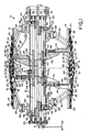
- a rotatable belt folding drum 10 having a cylindrical main shaft 12 mounted on a drive shaft 14 rotatably supported in a housing (not shown).
- the belt folding drum 10 has a plurality of circumferentially spaced drum segments 16 positioned around the main shaft 12 and expandable from the diameter shown in the upper part of Fig 1 to the diameter shown in the lower part of Fig 1.
- a bladder support bracket 18, shown more clearly in Figs 5 and 6, is slidably mounted on each of the segments 16 at each side of a centerplane A-A of the drum 10.
- the bladder support bracket 18 has a groove 20 for seating a nose portion 22 of a turnup bladder 24 positioned around the drum segments 16.
- a turnup bladder 24 is positioned at each side of the centerplane A-A and has a cavity 26 for inflation.
- the turnup bladder 24 may be of a resilient material such as rubber reinforced with plies of fabric in such a manner that upon inflation the end of the bladder will turn up an edge 28 of a radial tire belt 30 on the drum 10 about a fold line 32 of the bladder.
- Each bladder support bracket 18 is connected to a slider bar 34 extending through slots 35 in the segments 16.
- the slider bar 34 has ribs 36 in sliding engagement with radially extending grooves 38 in plates 40 mounted on central hub assemblies which include central outer hubs 42 and central inner hubs 44.
- the central outer hubs 42 are annular and have a cylindrical inner surface slidably mounted on the outer surface of the main shaft 12.
- the central outer hubs 42 are connected to the central inner hubs 44 by fasteners such as bolts 46 extending through slots in the main shaft 12.
- the distance between the bladders 24 on one side of the centerplane A-A and the bladder on the other side is controlled by spacing screws 48 extending from an outboard end 50 to an inboard end 52 of the main shaft 12.
- the spacing screws 48 have threaded portions 54 in threaded engagement with the central inner hubs 44.
- the threaded portions 54 have threads of opposite hand at positions on opposite sides of the centerplane A-A for moving the central inner hubs 44 in opposite directions upon rotation of the spacing screws 48 to lengthen or shorten the distance between the bladder support bracket 18 connected to the slider bar 34 at one side of the centerplane A-A and the bladder support bracket connected to the slider bar on the other side of the centerplane for each of the segments 16.
- the spacing screws 48 have sprockets 56 at the outboard end 50 which are engaged by a chain 58.
- a crank 60 may be mounted on the outboard end of one of the spacing screws 48 for turning the screw and the sprockets 56 causing the central inner hubs 44 to move in opposite directions depending upon the direction of rotation of the screws. In this way, the space between the bladder support bracket 18 connected to one of the central outer hubs 42 and the bladder support bracket connected to the other of the central outer hubs can be lengthened or shortened as desired.
- each bladder support bracket 18 and central filler block 62 has a matching surface 69 for engagement with a supporting surface of each of the segments 16. In this way, each bladder support bracket 18 and central filler block 62 will be stressed in compression in operation and need not be of a material having strength in tension.
- a stetchable cylindrical sleeve 70 of resilient material having a cylindrical inner surface 72 for seating on the central filler block of each of the drum segments 16.
- the cylindrical sleeve 70 may also have a contoured radially outer surface 74 for shaping the belt 30 and the other belts of the belt package.
- the inflatable turnup bladder 24 mounted on the bladder support bracket 18 at each side of each of the drum segments 16 is designed to fold over at the fold line 32; however, the axial position of the fold line at different circumferential sections of the bladder may vary.
- An adjustable connection between each slider bar 34 and each bladder support bracket 18 includes an adjusting screw 76 rotatably mounted in a hole 78 and threaded in a threaded hole 80 in the slider bar 34.
- the adjusting screw 76 is prevented from moving axially in the hole 78 by a collar in a slot 81 in the bladder support bracket 18, shown in Fig 5, so that upon rotation of the adjusting screw relative axial movement of the bladder support bracket on the drum segment 16 is provided to position the fold line 32 in a single plane perpendicular to the axis of the main shaft 12.
- This adjustment for each of the drum segments 16 can be made by projecting a lighted line on the drum surface at the fold line 32 prior to applying the belt 30.
- the bladder 24 may then be inflated to determine the actual position of the fold line 32.
- the adjusting screw 76 for each of the segments 16 may be rotated where the fold line 32 does not match with the projected lighted line until the fold line coincides with the lighted guide line on the drum surface.
- each of the drum segments 16 is connected by a pair of links 84 to drum expanding hub assemblies 86 and 88 at positions on opposite sides of the centerplane A-A and spaced outside the central hub assemblies.
- the links 84 may be pivotally connected to the segments 16 by pins extending through holes 89 in the segments, as shown in Fig 4.
- Each of the drum expanding hub assemblies 86 and 88 has an outer drum expanding hub 90 slidably mounted on the main shaft 12 and connected to an inner drum expanding hub 92 by suitable fasteners such as bolts 94.
- the inner drum expanding hub 92 of each of the drum expanding hub assemblies 86 and 88 is threaded for threaded engagement with a drum diameter control screw 96 rotatably mounted at the inboard end 52 and outboard end 50 of the main shaft 12.
- the threads of the drum diameter control screw 96 in engagement with the inner drum expanding hub 92 of the drum expanding hub assembly 88 are of opposite hand to the threads in engagement with the inner drum expanding hub of the drum expanding hub assembly 86 so that upon rotation of the drum diameter control screw in one direction, the drum expanding hub assembly 86 will be moved away from the drum expanding hub assembly 88 to decrease the diameter of the drum 10.
- the drum diameter control screw 96 may be connected to a suitable drive means and controls set and calibrated so that the desired diameter of the drum 10 can be provided by selected positioning of the drum expanding hub assemblies 86 and 88 through rotation of the drum diameter control screw.
- Initial expansion of the drum 10 to stretch the belt 30 after application on the drum may also be provided by rotating the drum diameter control screw 96 so as to expand the segments 16 a desired amount.
- drum 10 can be adjusted to build radial tire belt packages over a wide range of widths and diameters. No assembly or disassembly is required when the diameter of the drum 10 is adjusted; however, in some instances, the cylindrical sleeve 70 may be replaced with a sleeve having a different diameter.
- the cylindrical sleeve 70 is preferably of a stretchable, resilient polyurethane composition having a hardness of about 80 Shore A with a controlled modulus of elasticity in the range of about 300 to about 450 psi at 20 percent elongation, and in the range of about 475 to about 600 psi at 50 percent elongation.
- the cylindrical sleeve 70 also has an ultimate tensile strength in the range of about 2,000 to about 3,000 psi and a trouser (split) tear resistance of at least 100 lbs/inch.
- the sleeve 70 is elongated not more than 50 percent.
- the cylindrical sleeve 70 may be stretched to 50 percent elongation over 100 cycles with the permanent set being less than one percent insuring the return of the sleeve to its original position upon contraction of the drum 10. This is important so that a centering rib 98 on a cylindrical inner surface 72 of the sleeve 70 remains in engagement with a center slot 100 in the central filler block 62.
- the resistance to expansion of the segments 16 must be less than the forces available for expanding the segments.
- each central filler block 62 and each bladder support bracket 18 may be made of a rigid, foamed polyurethane composition having a Young's modulus of about 90,000 psi with a yield module of about 130,000 psi, an ultimate elongation of less than 10 percent, a Gardner impact of over 140 inch pounds, a Shore D hardness of at least 50 and a density of from about 30 to 40 lbs/cubic foot and preferably about 31 to 33.
- the parts can be molded to the desired dimensions without requiring extensive machining. The parts have dimensional stability and will not change shape after being used for a period of time.
- the parts are relatively light in weight and resist denting or other damage during handling and in operation.
- the central filler block 62 may be molded at one length and then cut-to-length by a band saw at the factory.
- the belt folding drum 10 is set to provide the desired spacing between the bladder support bracket 18 on one side of each of the segments 16 and the bladder support bracket on the other side of each of the segments by turning the crank 60 in the desired direction which causes the spacing screws 48 to turn and move the central inner hubs 44 and central outer hubs 42 apart or together the desired amount.
- Fine tuning is provided by turning the adjusting screw 76 in the bladder support bracket 18 for each of the segments 16 until the fold line 32 of each bladder 24 is in a single plane perpendicular to an axis B-B of the main shaft 12.
- a central filler block 62 of the appropriate length is fastened to each of the segments 16 and a cylindrical sleeve 70 of desired diameter is resiliently stretched over the central filler blocks.
- the desired diameter of the drum 10 may then be provided by turning the drum diameter control screw 96 a predetermined amount causing the drum expanding hub assembly 86 to move closer or farther apart from the drum expanding hub assembly 88.
- the drum 10 is then rotated on the drive shaft 14 and the initial belt 30 wrapped around the drum.
- the segments 16 may be expanded an additional amount by rotating the drum diameter control screw 96 and thereby place the initial belt 30 in tension. This is important for providing a tight fold without trapped air.
- Additional belts may then be wrapped around the initial belt 30 and finally each edge 28 of the initial belt folded around the other belts by inflating the turnup bladder 24 on each side of the drum 10. This is accomplished by communicating air through the conduits 83 to the passages 82 in a slider bar 34 on each side of the centerplane A-A. After each edge 28 is folded over the belt package, the bladder 24 on each side of each of the drum segments 16 is deflated and the drum segments retracted by turning the drum diameter control screw 96 to retract the segments so that the finished belt package may be removed from the drum 10.
Landscapes
- Engineering & Computer Science (AREA)
- Mechanical Engineering (AREA)
- Manufacturing & Machinery (AREA)
- Tyre Moulding (AREA)
Applications Claiming Priority (2)
| Application Number | Priority Date | Filing Date | Title |
|---|---|---|---|
| US210391 | 1988-06-22 | ||
| US07/210,391 US4859272A (en) | 1988-06-22 | 1988-06-22 | Radial tire belt folding drum |
Publications (3)
| Publication Number | Publication Date |
|---|---|
| EP0348336A2 true EP0348336A2 (de) | 1989-12-27 |
| EP0348336A3 EP0348336A3 (de) | 1991-10-02 |
| EP0348336B1 EP0348336B1 (de) | 1993-12-29 |
Family
ID=22782723
Family Applications (1)
| Application Number | Title | Priority Date | Filing Date |
|---|---|---|---|
| EP89630105A Expired - Lifetime EP0348336B1 (de) | 1988-06-22 | 1989-06-14 | Trommel zum Falten von Gürtellagen eines Radialreifens |
Country Status (9)
| Country | Link |
|---|---|
| US (1) | US4859272A (de) |
| EP (1) | EP0348336B1 (de) |
| JP (1) | JP2672368B2 (de) |
| KR (1) | KR960012434B1 (de) |
| AU (1) | AU610000B2 (de) |
| BR (1) | BR8902671A (de) |
| CA (1) | CA1305031C (de) |
| DE (1) | DE68911765T2 (de) |
| MX (1) | MX167388B (de) |
Cited By (2)
| Publication number | Priority date | Publication date | Assignee | Title |
|---|---|---|---|---|
| WO2006003054A1 (de) * | 2004-07-06 | 2006-01-12 | Continental Aktiengesellschaft | Verfahren und vorrichtung zum aufbau eines radialreifens |
| CN103465488A (zh) * | 2013-06-18 | 2013-12-25 | 软控股份有限公司 | 一种轮胎胎胚成型鼓及成型方法 |
Families Citing this family (9)
| Publication number | Priority date | Publication date | Assignee | Title |
|---|---|---|---|---|
| KR950007656B1 (ko) * | 1990-10-31 | 1995-07-14 | 스미토오 라버 인더스트리스주식회사 | 밴드부재 성형장치 |
| US6193599B1 (en) * | 1998-10-20 | 2001-02-27 | Asahi Seiko Co., Ltd. | Coin hopper device |
| JP2002536208A (ja) * | 1999-02-03 | 2002-10-29 | ザ・グッドイヤー・タイヤ・アンド・ラバー・カンパニー | 調整可能なタイヤ製造用輪郭ドラムとドラム上でのタイヤ製造方法 |
| US6723195B1 (en) | 1999-02-03 | 2004-04-20 | The Goodyear Tire & Rubber Company | Adjustable tire building contour drum and method of building tire thereon |
| US6488797B1 (en) | 2000-05-12 | 2002-12-03 | Bridgestone/Firestone North American Tire, Llc | First stage run flat tire building drum and method of using same |
| KR100963503B1 (ko) * | 2008-08-18 | 2010-06-15 | (주)세화아이엠씨 | 그린타이어 성형드럼장치 |
| CN102300700B (zh) * | 2008-12-17 | 2015-09-02 | 倍耐力轮胎股份公司 | 用于构造车轮的生轮胎的处理和设备 |
| DE102012014987B4 (de) * | 2012-07-27 | 2020-10-15 | Harburg-Freudenberger Maschinenbau Gmbh | Hochschlagvorrichtung für Reifenseitenwände |
| CN110696400B (zh) * | 2019-11-15 | 2024-12-31 | 软控股份有限公司 | 三角胶成型鼓装置 |
Family Cites Families (18)
| Publication number | Priority date | Publication date | Assignee | Title |
|---|---|---|---|---|
| US2603580A (en) * | 1949-07-07 | 1952-07-15 | Us Rubber Co | Tire building drum |
| US2603581A (en) * | 1949-12-13 | 1952-07-15 | Us Rubber Co | Tire building drum |
| GB872038A (en) * | 1956-11-17 | 1961-07-05 | Dunlop Rubber Co | Improvements in or relating to tyre building apparatus |
| GB1158771A (en) * | 1966-01-01 | 1969-07-16 | Dunlop Co Ltd | Method for Reducing Adhesion |
| BR6794587D0 (pt) * | 1966-12-22 | 1973-06-12 | Pirelli | Tambor para a confeccao de carcacas de pneumaticos |
| US3644162A (en) * | 1970-07-06 | 1972-02-22 | Goodyear Tire & Rubber | Tire-building drum |
| US3687756A (en) * | 1970-07-06 | 1972-08-29 | Goodyear Tire & Rubber | Method and apparatus for stripping flexible article from a building drum |
| US3787262A (en) * | 1971-09-24 | 1974-01-22 | Goodyear Tire & Rubber | Tire building drum |
| US3833445A (en) * | 1972-01-14 | 1974-09-03 | Nat Standard Co | Tire building apparatus for building tires |
| US3813271A (en) * | 1972-06-28 | 1974-05-28 | Goodyear Tire & Rubber | Belt building drum |
| CA1062594A (en) * | 1974-05-22 | 1979-09-18 | Frank R. Jellison | Building machine having an infinite number of drum settings |
| JPS5463184A (en) * | 1977-10-28 | 1979-05-21 | Bridgestone Tire Co Ltd | Tire forming drum |
| US4290472A (en) * | 1978-09-21 | 1981-09-22 | National-Standard Company | Tire building apparatus |
| US4427473A (en) * | 1979-02-22 | 1984-01-24 | Nrm Corporation | Belt folding machine and method |
| JPS55114556A (en) * | 1979-02-22 | 1980-09-03 | Nrm Corp | Belt folding machine and its belt folding method |
| JPS57208233A (en) * | 1981-06-18 | 1982-12-21 | Mitsubishi Heavy Ind Ltd | Method and apparatus for manufacturing radial tire |
| JPS5833444A (ja) * | 1981-08-24 | 1983-02-26 | Bridgestone Corp | ラジアルタイヤ用ブレ−カ−層の折り返し方法および折り返し装置 |
| JPS59202837A (ja) * | 1983-05-02 | 1984-11-16 | Bridgestone Corp | タイヤ成形装置 |
-
1988
- 1988-06-22 US US07/210,391 patent/US4859272A/en not_active Expired - Lifetime
-
1989
- 1989-06-07 BR BR898902671A patent/BR8902671A/pt not_active IP Right Cessation
- 1989-06-14 DE DE68911765T patent/DE68911765T2/de not_active Expired - Fee Related
- 1989-06-14 EP EP89630105A patent/EP0348336B1/de not_active Expired - Lifetime
- 1989-06-21 MX MX016551A patent/MX167388B/es unknown
- 1989-06-21 CA CA000603518A patent/CA1305031C/en not_active Expired - Fee Related
- 1989-06-21 JP JP1156909A patent/JP2672368B2/ja not_active Expired - Fee Related
- 1989-06-21 KR KR1019890008556A patent/KR960012434B1/ko not_active Expired - Fee Related
- 1989-06-22 AU AU36698/89A patent/AU610000B2/en not_active Ceased
Cited By (3)
| Publication number | Priority date | Publication date | Assignee | Title |
|---|---|---|---|---|
| WO2006003054A1 (de) * | 2004-07-06 | 2006-01-12 | Continental Aktiengesellschaft | Verfahren und vorrichtung zum aufbau eines radialreifens |
| US7837816B2 (en) | 2004-07-06 | 2010-11-23 | Continental Aktiengesellschaft | Method and device for the construction of a radial tire |
| CN103465488A (zh) * | 2013-06-18 | 2013-12-25 | 软控股份有限公司 | 一种轮胎胎胚成型鼓及成型方法 |
Also Published As
| Publication number | Publication date |
|---|---|
| CA1305031C (en) | 1992-07-14 |
| JPH0245132A (ja) | 1990-02-15 |
| JP2672368B2 (ja) | 1997-11-05 |
| KR900000225A (ko) | 1990-01-30 |
| MX167388B (es) | 1993-03-19 |
| AU610000B2 (en) | 1991-05-09 |
| DE68911765T2 (de) | 1994-06-09 |
| EP0348336B1 (de) | 1993-12-29 |
| BR8902671A (pt) | 1990-01-23 |
| AU3669889A (en) | 1990-01-04 |
| US4859272A (en) | 1989-08-22 |
| DE68911765D1 (de) | 1994-02-10 |
| KR960012434B1 (ko) | 1996-09-20 |
| EP0348336A3 (de) | 1991-10-02 |
Similar Documents
| Publication | Publication Date | Title |
|---|---|---|
| US3475254A (en) | Tire building machine | |
| AU2002301010B2 (en) | Tire Building Drum Having Expandable Center Section and Independently Expandable Bead Lock Assemblies in the End Sections | |
| EP0348336B1 (de) | Trommel zum Falten von Gürtellagen eines Radialreifens | |
| US3833444A (en) | Tire building apparatus of building tires | |
| US6585022B1 (en) | Tire building method and apparatus | |
| KR100894782B1 (ko) | 타이어 조립 드럼 | |
| CA2006988C (en) | Expandable tire building drum | |
| US4427473A (en) | Belt folding machine and method | |
| EP1286827A4 (de) | Süeizbarer dorn mit einstellbarer breite | |
| EP1771295B1 (de) | Reifentrommelanordnung mit umschlagmechanismen zum bau eines unvulkanisierten reifens | |
| JP3364280B2 (ja) | タイヤ成形ドラム及び生タイヤ製造方法 | |
| US5116449A (en) | Grooved drum for tire building machine | |
| JP3650843B2 (ja) | タイヤの製造方法および機械 | |
| US6673183B2 (en) | Method and apparatus for tire carcass positioning on a drum | |
| US4402782A (en) | Tire building machine | |
| CA1149273A (en) | Tire building machine | |
| EP0015113B1 (de) | Reifen Aufbaumaschine und Verfahren | |
| US4001070A (en) | Tire building apparatus | |
| EP0692368B1 (de) | Reifenaufbautrommel und Verfahren zum Herstellen eines Rohreifens | |
| CN101143493A (zh) | 用于制造车轮轮胎的成型方法和转鼓 | |
| WO2000012297A1 (en) | Tire building method and apparatus | |
| JPH11157306A (ja) | 車両の車輪用タイヤ及びそのリム並びにその車輪 |
Legal Events
| Date | Code | Title | Description |
|---|---|---|---|
| PUAI | Public reference made under article 153(3) epc to a published international application that has entered the european phase |
Free format text: ORIGINAL CODE: 0009012 |
|
| 17P | Request for examination filed |
Effective date: 19890701 |
|
| AK | Designated contracting states |
Kind code of ref document: A2 Designated state(s): DE FR GB IT LU |
|
| PUAL | Search report despatched |
Free format text: ORIGINAL CODE: 0009013 |
|
| AK | Designated contracting states |
Kind code of ref document: A3 Designated state(s): DE FR GB IT LU |
|
| RHK1 | Main classification (correction) |
Ipc: B29D 30/70 |
|
| 17Q | First examination report despatched |
Effective date: 19930315 |
|
| GRAA | (expected) grant |
Free format text: ORIGINAL CODE: 0009210 |
|
| AK | Designated contracting states |
Kind code of ref document: B1 Designated state(s): DE FR GB IT LU |
|
| REF | Corresponds to: |
Ref document number: 68911765 Country of ref document: DE Date of ref document: 19940210 |
|
| ET | Fr: translation filed | ||
| ITF | It: translation for a ep patent filed | ||
| EPTA | Lu: last paid annual fee | ||
| PLBE | No opposition filed within time limit |
Free format text: ORIGINAL CODE: 0009261 |
|
| STAA | Information on the status of an ep patent application or granted ep patent |
Free format text: STATUS: NO OPPOSITION FILED WITHIN TIME LIMIT |
|
| 26N | No opposition filed | ||
| PGFP | Annual fee paid to national office [announced via postgrant information from national office to epo] |
Ref country code: LU Payment date: 20000324 Year of fee payment: 12 |
|
| PG25 | Lapsed in a contracting state [announced via postgrant information from national office to epo] |
Ref country code: LU Free format text: LAPSE BECAUSE OF NON-PAYMENT OF DUE FEES Effective date: 20010614 |
|
| REG | Reference to a national code |
Ref country code: GB Ref legal event code: IF02 |
|
| PGFP | Annual fee paid to national office [announced via postgrant information from national office to epo] |
Ref country code: GB Payment date: 20050506 Year of fee payment: 17 |
|
| PGFP | Annual fee paid to national office [announced via postgrant information from national office to epo] |
Ref country code: FR Payment date: 20050602 Year of fee payment: 17 |
|
| PGFP | Annual fee paid to national office [announced via postgrant information from national office to epo] |
Ref country code: DE Payment date: 20050630 Year of fee payment: 17 |
|
| PG25 | Lapsed in a contracting state [announced via postgrant information from national office to epo] |
Ref country code: GB Free format text: LAPSE BECAUSE OF NON-PAYMENT OF DUE FEES Effective date: 20060614 |
|
| PGFP | Annual fee paid to national office [announced via postgrant information from national office to epo] |
Ref country code: IT Payment date: 20060630 Year of fee payment: 18 |
|
| PG25 | Lapsed in a contracting state [announced via postgrant information from national office to epo] |
Ref country code: DE Free format text: LAPSE BECAUSE OF NON-PAYMENT OF DUE FEES Effective date: 20070103 |
|
| GBPC | Gb: european patent ceased through non-payment of renewal fee |
Effective date: 20060614 |
|
| REG | Reference to a national code |
Ref country code: FR Ref legal event code: ST Effective date: 20070228 |
|
| PG25 | Lapsed in a contracting state [announced via postgrant information from national office to epo] |
Ref country code: FR Free format text: LAPSE BECAUSE OF NON-PAYMENT OF DUE FEES Effective date: 20060630 |
|
| PG25 | Lapsed in a contracting state [announced via postgrant information from national office to epo] |
Ref country code: IT Free format text: LAPSE BECAUSE OF NON-PAYMENT OF DUE FEES Effective date: 20070614 |