EP0348022B1 - Fastener for releasably securing together a plurality of sheet or plate members e.g. printing plates - Google Patents
Fastener for releasably securing together a plurality of sheet or plate members e.g. printing plates Download PDFInfo
- Publication number
- EP0348022B1 EP0348022B1 EP89303067A EP89303067A EP0348022B1 EP 0348022 B1 EP0348022 B1 EP 0348022B1 EP 89303067 A EP89303067 A EP 89303067A EP 89303067 A EP89303067 A EP 89303067A EP 0348022 B1 EP0348022 B1 EP 0348022B1
- Authority
- EP
- European Patent Office
- Prior art keywords
- fastening
- spigot
- apertures
- stack
- plates
- Prior art date
- Legal status (The legal status is an assumption and is not a legal conclusion. Google has not performed a legal analysis and makes no representation as to the accuracy of the status listed.)
- Expired - Lifetime
Links
- 238000000034 method Methods 0.000 claims abstract description 19
- 230000002093 peripheral effect Effects 0.000 claims description 6
- 238000005452 bending Methods 0.000 claims description 2
- 238000003780 insertion Methods 0.000 claims description 2
- 230000037431 insertion Effects 0.000 claims description 2
- 239000002390 adhesive tape Substances 0.000 description 3
- 239000004743 Polypropylene Substances 0.000 description 1
- 239000002131 composite material Substances 0.000 description 1
- 238000010276 construction Methods 0.000 description 1
- 230000005764 inhibitory process Effects 0.000 description 1
- 238000002347 injection Methods 0.000 description 1
- 239000007924 injection Substances 0.000 description 1
- 239000000463 material Substances 0.000 description 1
- 239000004033 plastic Substances 0.000 description 1
- 229920003023 plastic Polymers 0.000 description 1
- -1 polypropylene Polymers 0.000 description 1
- 229920001155 polypropylene Polymers 0.000 description 1
- 230000000452 restraining effect Effects 0.000 description 1
- 238000000926 separation method Methods 0.000 description 1
Images


Classifications
-
- F—MECHANICAL ENGINEERING; LIGHTING; HEATING; WEAPONS; BLASTING
- F16—ENGINEERING ELEMENTS AND UNITS; GENERAL MEASURES FOR PRODUCING AND MAINTAINING EFFECTIVE FUNCTIONING OF MACHINES OR INSTALLATIONS; THERMAL INSULATION IN GENERAL
- F16B—DEVICES FOR FASTENING OR SECURING CONSTRUCTIONAL ELEMENTS OR MACHINE PARTS TOGETHER, e.g. NAILS, BOLTS, CIRCLIPS, CLAMPS, CLIPS OR WEDGES; JOINTS OR JOINTING
- F16B21/00—Means for preventing relative axial movement of a pin, spigot, shaft or the like and a member surrounding it; Stud-and-socket releasable fastenings
- F16B21/06—Releasable fastening devices with snap-action
- F16B21/07—Releasable fastening devices with snap-action in which the socket has a resilient part
- F16B21/071—Releasable fastening devices with snap-action in which the socket has a resilient part the socket being integrally formed with a component to be fasted, e.g. a sheet, plate or strip
-
- B—PERFORMING OPERATIONS; TRANSPORTING
- B42—BOOKBINDING; ALBUMS; FILES; SPECIAL PRINTED MATTER
- B42F—SHEETS TEMPORARILY ATTACHED TOGETHER; FILING APPLIANCES; FILE CARDS; INDEXING
- B42F15/00—Suspended filing appliances
- B42F15/0011—Suspended filing appliances for sheets, stacks of temporarily bound sheets
- B42F15/0052—Suspended filing appliances for sheets, stacks of temporarily bound sheets for suspending stacks of temporarily bound sheets
- B42F15/0064—Suspended filing appliances for sheets, stacks of temporarily bound sheets for suspending stacks of temporarily bound sheets with movable suspension means
-
- B—PERFORMING OPERATIONS; TRANSPORTING
- B42—BOOKBINDING; ALBUMS; FILES; SPECIAL PRINTED MATTER
- B42F—SHEETS TEMPORARILY ATTACHED TOGETHER; FILING APPLIANCES; FILE CARDS; INDEXING
- B42F3/00—Sheets temporarily attached together involving perforations; Means therefor; Sheet details therefor
- B42F3/04—Attachment means of ring, finger or claw form
-
- F—MECHANICAL ENGINEERING; LIGHTING; HEATING; WEAPONS; BLASTING
- F16—ENGINEERING ELEMENTS AND UNITS; GENERAL MEASURES FOR PRODUCING AND MAINTAINING EFFECTIVE FUNCTIONING OF MACHINES OR INSTALLATIONS; THERMAL INSULATION IN GENERAL
- F16B—DEVICES FOR FASTENING OR SECURING CONSTRUCTIONAL ELEMENTS OR MACHINE PARTS TOGETHER, e.g. NAILS, BOLTS, CIRCLIPS, CLAMPS, CLIPS OR WEDGES; JOINTS OR JOINTING
- F16B19/00—Bolts without screw-thread; Pins, including deformable elements; Rivets
-
- F—MECHANICAL ENGINEERING; LIGHTING; HEATING; WEAPONS; BLASTING
- F16—ENGINEERING ELEMENTS AND UNITS; GENERAL MEASURES FOR PRODUCING AND MAINTAINING EFFECTIVE FUNCTIONING OF MACHINES OR INSTALLATIONS; THERMAL INSULATION IN GENERAL
- F16B—DEVICES FOR FASTENING OR SECURING CONSTRUCTIONAL ELEMENTS OR MACHINE PARTS TOGETHER, e.g. NAILS, BOLTS, CIRCLIPS, CLAMPS, CLIPS OR WEDGES; JOINTS OR JOINTING
- F16B21/00—Means for preventing relative axial movement of a pin, spigot, shaft or the like and a member surrounding it; Stud-and-socket releasable fastenings
- F16B21/06—Releasable fastening devices with snap-action
- F16B21/07—Releasable fastening devices with snap-action in which the socket has a resilient part
- F16B21/073—Releasable fastening devices with snap-action in which the socket has a resilient part the socket having a resilient part on its inside
-
- F—MECHANICAL ENGINEERING; LIGHTING; HEATING; WEAPONS; BLASTING
- F16—ENGINEERING ELEMENTS AND UNITS; GENERAL MEASURES FOR PRODUCING AND MAINTAINING EFFECTIVE FUNCTIONING OF MACHINES OR INSTALLATIONS; THERMAL INSULATION IN GENERAL
- F16B—DEVICES FOR FASTENING OR SECURING CONSTRUCTIONAL ELEMENTS OR MACHINE PARTS TOGETHER, e.g. NAILS, BOLTS, CIRCLIPS, CLAMPS, CLIPS OR WEDGES; JOINTS OR JOINTING
- F16B21/00—Means for preventing relative axial movement of a pin, spigot, shaft or the like and a member surrounding it; Stud-and-socket releasable fastenings
- F16B21/10—Means for preventing relative axial movement of a pin, spigot, shaft or the like and a member surrounding it; Stud-and-socket releasable fastenings by separate parts
- F16B21/16—Means for preventing relative axial movement of a pin, spigot, shaft or the like and a member surrounding it; Stud-and-socket releasable fastenings by separate parts with grooves or notches in the pin or shaft
-
- G—PHYSICS
- G03—PHOTOGRAPHY; CINEMATOGRAPHY; ANALOGOUS TECHNIQUES USING WAVES OTHER THAN OPTICAL WAVES; ELECTROGRAPHY; HOLOGRAPHY
- G03F—PHOTOMECHANICAL PRODUCTION OF TEXTURED OR PATTERNED SURFACES, e.g. FOR PRINTING, FOR PROCESSING OF SEMICONDUCTOR DEVICES; MATERIALS THEREFOR; ORIGINALS THEREFOR; APPARATUS SPECIALLY ADAPTED THEREFOR
- G03F9/00—Registration or positioning of originals, masks, frames, photographic sheets or textured or patterned surfaces, e.g. automatically
Definitions
- This invention relates to releasable fasteners for securing together a plurality of sheet or plate members.
- the fastener of the invention is particularly, but not exclusively, suitable for securing together two or more colourlithographic printing plates or the sheets of photographic film used in the photolithographic process for making the plates.
- the invention also concerns a method for releasably securing together a plurality of such lithographic printing plates or sheets of film.
- a colourlithographic printing process involves the transfer onto an image receptor sheet of a plurality of different colour components of the required image.
- the ink for each successive image component is transferred by an offset process, the initial ink pattern being formed on the surface of a specially prepared lithographic plate in the form of a thin metallic sheet secured onto the surface of a carrier roller.
- the printing machine With means to locate the printing plates correctly on their respective support rollers.
- Such locating means normally comprises projections which engage in preformed registration apertures in the printing plates.
- the equipment used by the printing plate maker is suitably adapted to punch these registration holes in an accepted standard format according to the type of printing machine for which the plates are intended, and also to form the respective colour component print patterns in correct positional relationship with these punched registration holes.
- each set of plates is assembled as a stack and secured together.
- This is normally done using pieces of adhesive tape secured at the corners of the stack, but this somewhat crude technique has certain drawbacks.
- the tape must be very carefully applied otherwise the plate may not be sufficiently firmly secured together to prevent face-to-face sliding of the plates which causes damage to the image patterns carried on the faces of the plates. Accordingly, this adhesive tape method is time-consuming and awkward to perform.
- the tape often splits during transport, allowing such sliding to occur, with the above-noted undesirable results.
- the tape must be completely removed by the printer otherwise printing errors may occur; this tape removal is again a time-consuming and awkward job to perform.
- the printer will normally store the printing plates, and once again each set of plates may for convenience of storage be secured together, for which purpose the above-mentioned troublesome adhesive tape method is normally employed.
- the process used by the plate maker for making the printing plates is a photographic process involving the use of sheets of photographic film. These sheets, or transparent carrier sheets on which they are mounted, are also punched with registration holes, to ensure correct relative positioning of the plates and films during the process, and the above-noted problems of securing the sets of films together for transport and storage are commonly encountered.
- the present invention aims to alleviate these problems and to that end provides in one aspect a method of releasably and nonslidably securing together a stack of printing plates each of which is provided adjacent an edge thereof with first and second registration apertures for location of the plate in a printing apparatus, the method comprising the steps of assembling the stack of printing plates with their corresponding edges registered and their corresponding first and second apertures aligned in sets, and attaching respective first and second fastening devices to the stack at the respective sets of said first and second aligned apertures, each fastening device comprising an integrally formed, one-piece element which includes first and second fastening portions spaced apart along an elongate flexible connector element, one of said fastening portions having a substantially flat base from which a generally cylindrical spigot element projects, and the other of said fastening portions having an attachment aperture adapted to receive and to form a releasable, snap-action fastening with said spigot element, the attachment step including, in respect of each set of aligned aperture
- the invention also provides a fastening device for releasably securing together a plurality of sheet or plate members assembled in face-to-face or back-to-back contact.
- AU-B-518608 discloses a one-piece fastener, composed of interfitting parts interconnected by a flexible strip, for grouping together a pile of superimposed perforated sheets. Each part has a head which in use contacts an outer sheet of the pile and a stalk extending substantially at right angles from the head passing through the perforations of the or each sheet. The stalks are mutually connectable by a push fit, one stalk fitting coaxially into the other, and separable by pulling to disconnect the stalks.
- the fastener is quite satisfactory for many applications, it may cause problems when used as a fastening device in a method according to the first aspect of the invention. More particularly, the construction of the fastener could allow a slight degree of relative sliding movement of the top plates if used to fasten together a stack of printing plates, leading to the undesirable damage to the images on the plates, as mentioned earlier.
- a fastening device for releasably securing together a plurality of printing plates assembled in face-to-face or back-to-back contact, said plates being provided with correspondingly positioned, shaped and dimensioned registration apertures
- the fastening device comprising an integrally formed, one-piece element which includes first and second fastening portions spaced apart along an elongate flexible connector element, said fastening portions being positionable from opposite sides of the assembly of plates with said connector element extending over an edge of the assembly, said fastening portions being releasably interconnectable, with a generally cylindrical spigot element of one of them projecting through the aligned apertures, wherein said one of the fastening portions is formed with a substantially flat base from which the spigot element projects, said spigot element having a peripheral surface for engaging with inside edges of said apertures, said peripheral surface being capable, throughout a portion of the spigot's length, of so engaging said inside edges as to inhibit relative sliding
- the spigot includes an attachment pin which is generally coaxial with, and lies radially inwardly of said peripheral surface, and has in the upper spigot part an outer surface which is formed with a plurality of circumferentially spaced recesses, or undercuts, and wherein the edge of said attachment aperture is formed with a corresponding plurality of circumferentially spaced flexible lips, said lips being adapted to be flexed by insertion of the attachment pin into the attachment aperture and to engage by snap action into the corresponding recesses or undercuts.
- the lower spigot part has a circumferentially continuous wall for engaging in the aligned apertures of the plates
- said upper spigot part comprises a plurality of radially disposed circumferentially spaced elements extending axially away from the lower spigot part in a direction transverse to the plane of the base and having radially outer edges or surfaces which are contiguous with and continue in said direction from said wall, said attachment aperture in said other fastening portion having circumferentially spaced radially disposed aperture portions for receiving said elements of the upper spigot part, the arrangement thereby being such as to be devoid of any circumferentially extending gap between the spigot element and the other fastening portion into which one or more aperture edges of a said plate could slip when the two are mutually attached.
- a fastener comprises a one-piece element injection moulded from plastics material, e.g. polypropylene, and comprises first and second fastening portions in the form of head members 2 and 3 respectively, interconnected by a connector member in the form of an elongate flexible connecting strip 4.
- Each head member is generally circular, and is formed with a respective end tag 5, 6, the purpose of which will become clear as the description proceeds.
- the first head member 2 comprises a base 9 integrally formed with a spigot 7 including a cylindrical wall 8 projecting with its axis perpendicular to that of the base 9.
- the spigot 7 includes an attachment peg or pin 10 projecting perpendicularly from the base 9 beyond a chamfered rim 8a of the cylindrical wall 8, as can be best seen in Figure 2.
- This pin 10 is disposed radially inwardly of the wall 8 and is formed with a tapered head portion 11.
- the spigot 7 also includes three radially disposed, equally circumferentially spaced restraining web elements 12 which project from the base 9 and are integrally joined at their radially inner portions to the central pin 10 and at their radially outer portions to the cylindrical wall 8.
- the radially outer edges 13 of these elements 12 are, as can be seen from Figure 2, continuous with the sectional profile of the wall 8.
- Each of the three circumferential portions of the pin 10 between adjacent web elements 12 has an undercut 14.
- the second head member 3 is formed with an aperture 15 having a generally circular central portion 16 and three radially disposed, equally circumferentially spaced arms 17.
- an aperture 15 having a generally circular central portion 16 and three radially disposed, equally circumferentially spaced arms 17.
- a device described above with reference to Figures 1 to 3 is employed to secure together a stack of lithographic printing plates or photographic films 20 assembled with their registration holes 21 aligned.
- the spigot 7 of the first head member is pushed into the aligned holes 21 from one side of the stack until the base 9 comes into engagement with the outer face of the plate on that side;
- the height H of the cylindrical wall 7 is preferably slightly greater than the combined thickness of five standard printing plates this being the number in a standard colour lithographic plate set so that it will just project from the other side of the stack, as shown in Figure 5.
- this dimension H is approximately 3.3mm.
- a device with this magnitude of dimension H would accommodate a stack of up to seven such plates.
- the flexible connector 4 is then bent round the edge 22 of the stack of plates or films and the head member 3 is pushed onto the projecting head 11 of the pin 10 and portions 12 of the spigot.
- the arms 17 of the aperture 16 are correspondingly positioned with the retaining members 12 so as to accommodate them when the two head members are thus pushed together.
- Each pair of circumferentially adjacent arms 17 defines between them a respective flexible lip 23 which flexes outwardly as it rides down the surface of the conical head 11 during this attachment process, and eventually snaps back into the corresponding undercut 14.
- the diameter of the circular central portion 16 of the aperture 15 is smaller than the overall outer diameter of the pin 10 and accordingly the lips 23 engage tightly in the undercuts 14 to retain the fastener in the securing position shown in Figure 5.
- the tags 5 and 6 facilitate manual separation of the second head member 3 from the pin 10, and subsequent removal of the first head member 2 from the aligned apertures 21 of the printing plates.
- the fastener not only holds the printing plates together, but also inhibits any face-to-face sliding between them, which sliding could otherwise damage the component image patterns on their surfaces.
- This inhibition of sliding is accomplished by making the outer diameter of the spigot substantially the same as the diameter of the apertures 21.
- their outer edges 24 are contiguous with the sectional profile of the wall 8 as can be seen in Figure 5. Since these members 24 project right through the second head member 3 there is no possibility of the aperture edge portion of the plate 20a sliding between the chamfered upper rim 8a of the cylindrical wall 8 and the underface of the head member 3.
- Figure 7 shows a modified form of fastener having a form of spigot 7′ specially adapted to pass through a well-known form of non-circular registration aperture commonly used in lithographic printing techniques as a variant to the circular aperture.
- the shape of the spigot can be adapted for any shape of registration aperture.
- the above-described fastener is quick and easy to use and provides a secure and efficient means for releasably fixing printing plates together using an existing characteristic feature of such plates, namely the registration apertures.
Landscapes
- Engineering & Computer Science (AREA)
- General Engineering & Computer Science (AREA)
- Mechanical Engineering (AREA)
- Physics & Mathematics (AREA)
- General Physics & Mathematics (AREA)
- Printing Plates And Materials Therefor (AREA)
- Adhesive Tapes (AREA)
- Manufacture Or Reproduction Of Printing Formes (AREA)
- Photographic Processing Devices Using Wet Methods (AREA)
- Clamps And Clips (AREA)
- Connection Of Plates (AREA)
Abstract
Description
- This invention relates to releasable fasteners for securing together a plurality of sheet or plate members. The fastener of the invention is particularly, but not exclusively, suitable for securing together two or more colourlithographic printing plates or the sheets of photographic film used in the photolithographic process for making the plates. The invention also concerns a method for releasably securing together a plurality of such lithographic printing plates or sheets of film.
- A colourlithographic printing process involves the transfer onto an image receptor sheet of a plurality of different colour components of the required image. The ink for each successive image component is transferred by an offset process, the initial ink pattern being formed on the surface of a specially prepared lithographic plate in the form of a thin metallic sheet secured onto the surface of a carrier roller. To ensure that the successive image components are transferred with exact positional accuracy to provide a sharp composite image, it is known to provide the printing machine with means to locate the printing plates correctly on their respective support rollers. Such locating means normally comprises projections which engage in preformed registration apertures in the printing plates. The equipment used by the printing plate maker is suitably adapted to punch these registration holes in an accepted standard format according to the type of printing machine for which the plates are intended, and also to form the respective colour component print patterns in correct positional relationship with these punched registration holes.
- For transport from the plate maker to the printer, each set of plates is assembled as a stack and secured together. This is normally done using pieces of adhesive tape secured at the corners of the stack, but this somewhat crude technique has certain drawbacks. Firstly, the tape must be very carefully applied otherwise the plate may not be sufficiently firmly secured together to prevent face-to-face sliding of the plates which causes damage to the image patterns carried on the faces of the plates. Accordingly, this adhesive tape method is time-consuming and awkward to perform. Secondly, the tape often splits during transport, allowing such sliding to occur, with the above-noted undesirable results. Thirdly, the tape must be completely removed by the printer otherwise printing errors may occur; this tape removal is again a time-consuming and awkward job to perform.
- After printing, the printer will normally store the printing plates, and once again each set of plates may for convenience of storage be secured together, for which purpose the above-mentioned troublesome adhesive tape method is normally employed.
- The process used by the plate maker for making the printing plates is a photographic process involving the use of sheets of photographic film. These sheets, or transparent carrier sheets on which they are mounted, are also punched with registration holes, to ensure correct relative positioning of the plates and films during the process, and the above-noted problems of securing the sets of films together for transport and storage are commonly encountered.
- The present invention aims to alleviate these problems and to that end provides in one aspect a method of releasably and nonslidably securing together a stack of printing plates each of which is provided adjacent an edge thereof with first and second registration apertures for location of the plate in a printing apparatus, the method comprising the steps of assembling the stack of printing plates with their corresponding edges registered and their corresponding first and second apertures aligned in sets, and attaching respective first and second fastening devices to the stack at the respective sets of said first and second aligned apertures, each fastening device comprising an integrally formed, one-piece element which includes first and second fastening portions spaced apart along an elongate flexible connector element, one of said fastening portions having a substantially flat base from which a generally cylindrical spigot element projects, and the other of said fastening portions having an attachment aperture adapted to receive and to form a releasable, snap-action fastening with said spigot element, the attachment step including, in respect of each set of aligned apertures, passing the spigot element of a respective fastening device through that set of aligned apertures from one side of the stack, the spigot element engaging the inside edges of said apertures so as to be substantially immovable laterally with respect to said apertures, then bending the flexible connector element around the registered plate edges of the stack, and fastening said other fastening portion from the other side of the stack by way of said snap-action fastening to the part of the spigot element projecting through to said other side of the stack, whereby said fastening devices substantially prevent relative sliding movement of said printing plates.
- The invention also provides a fastening device for releasably securing together a plurality of sheet or plate members assembled in face-to-face or back-to-back contact. AU-B-518608 discloses a one-piece fastener, composed of interfitting parts interconnected by a flexible strip, for grouping together a pile of superimposed perforated sheets. Each part has a head which in use contacts an outer sheet of the pile and a stalk extending substantially at right angles from the head passing through the perforations of the or each sheet. The stalks are mutually connectable by a push fit, one stalk fitting coaxially into the other, and separable by pulling to disconnect the stalks.
- While this fastener is quite satisfactory for many applications, it may cause problems when used as a fastening device in a method according to the first aspect of the invention. More particularly, the construction of the fastener could allow a slight degree of relative sliding movement of the top plates if used to fasten together a stack of printing plates, leading to the undesirable damage to the images on the plates, as mentioned earlier.
- According to the second aspect of the invention, there is provided a fastening device for releasably securing together a plurality of printing plates assembled in face-to-face or back-to-back contact, said plates being provided with correspondingly positioned, shaped and dimensioned registration apertures, the fastening device comprising an integrally formed, one-piece element which includes first and second fastening portions spaced apart along an elongate flexible connector element, said fastening portions being positionable from opposite sides of the assembly of plates with said connector element extending over an edge of the assembly, said fastening portions being releasably interconnectable, with a generally cylindrical spigot element of one of them projecting through the aligned apertures, wherein said one of the fastening portions is formed with a substantially flat base from which the spigot element projects, said spigot element having a peripheral surface for engaging with inside edges of said apertures, said peripheral surface being capable, throughout a portion of the spigot's length, of so engaging said inside edges as to inhibit relative sliding movement of the plates, characterised in that said portion comprises a lower spigot part adjacent to the base and an upper spigot part contiguous with and projecting upwardly from said lower spigot part, and in that the other fastening portion is formed with an attachment aperture adapted to receive, and to form a releasable, snap-action fastening with, said upper spigot part.
- In the disclosed embodiments, the spigot includes an attachment pin which is generally coaxial with, and lies radially inwardly of said peripheral surface, and has in the upper spigot part an outer surface which is formed with a plurality of circumferentially spaced recesses, or undercuts, and wherein the edge of said attachment aperture is formed with a corresponding plurality of circumferentially spaced flexible lips, said lips being adapted to be flexed by insertion of the attachment pin into the attachment aperture and to engage by snap action into the corresponding recesses or undercuts.
- In the embodiments, the lower spigot part has a circumferentially continuous wall for engaging in the aligned apertures of the plates, and said upper spigot part comprises a plurality of radially disposed circumferentially spaced elements extending axially away from the lower spigot part in a direction transverse to the plane of the base and having radially outer edges or surfaces which are contiguous with and continue in said direction from said wall, said attachment aperture in said other fastening portion having circumferentially spaced radially disposed aperture portions for receiving said elements of the upper spigot part, the arrangement thereby being such as to be devoid of any circumferentially extending gap between the spigot element and the other fastening portion into which one or more aperture edges of a said plate could slip when the two are mutually attached.
- Preferred embodiments of the invention will now be described by way of example with reference to the accompanying drawings, in which:-
- Figure 1 is a plan view of a fastening device according to the present invention;
- Figure 2 is a side view of the fastening device shown in Figure 1;
- Figure 3 is a longitudinal sectional view of the fastening device of Figure 1, taken on line III-III;
- Figure 4 is a perspective view of a set of printing plates secured together with two fastening devices of the kind illustrated in Figures 1 to 3;
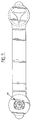
- Figure 5 is a sectional view through a fastening device of Figures 1 to 3 as used to secure together a set of printing plates; and
- Figure 6 illustrates schematically a different way of suspending a set of printing plates or films secured together by a pair of such fastening devices; and
- Figure 7 is a plan view of a modified form of fastening device.
- With reference to Figures 1 to 3, a fastener according to the invention comprises a one-piece element injection moulded from plastics material, e.g. polypropylene, and comprises first and second fastening portions in the form of
head members 2 and 3 respectively, interconnected by a connector member in the form of an elongateflexible connecting strip 4. Each head member is generally circular, and is formed with arespective end tag - The first head member 2 comprises a
base 9 integrally formed with a spigot 7 including acylindrical wall 8 projecting with its axis perpendicular to that of thebase 9. The spigot 7 includes an attachment peg or pin 10 projecting perpendicularly from thebase 9 beyond achamfered rim 8a of thecylindrical wall 8, as can be best seen in Figure 2. This pin 10 is disposed radially inwardly of thewall 8 and is formed with atapered head portion 11. - The spigot 7 also includes three radially disposed, equally circumferentially spaced restraining
web elements 12 which project from thebase 9 and are integrally joined at their radially inner portions to the central pin 10 and at their radially outer portions to thecylindrical wall 8. The radiallyouter edges 13 of theseelements 12 are, as can be seen from Figure 2, continuous with the sectional profile of thewall 8. - Each of the three circumferential portions of the pin 10 between
adjacent web elements 12 has an undercut 14. - The
second head member 3 is formed with anaperture 15 having a generally circularcentral portion 16 and three radially disposed, equally circumferentially spacedarms 17. On the side of thehead member 3 which, in the flat condition of the device shown in Figures 1 and 2, is on the side opposite to that of the spigot 7, there is formed acylindrical wall 18 encircling theaperture 15. - With reference to Figure 4 of the drawings, a device described above with reference to Figures 1 to 3 is employed to secure together a stack of lithographic printing plates or
photographic films 20 assembled with theirregistration holes 21 aligned. To secure the fastener, the spigot 7 of the first head member is pushed into the alignedholes 21 from one side of the stack until thebase 9 comes into engagement with the outer face of the plate on that side; the height H of the cylindrical wall 7 is preferably slightly greater than the combined thickness of five standard printing plates this being the number in a standard colour lithographic plate set so that it will just project from the other side of the stack, as shown in Figure 5. In one preferred embodiment for use with plates of 0.5mm thickness this dimension H is approximately 3.3mm. In fact, a device with this magnitude of dimension H would accommodate a stack of up to seven such plates. Theflexible connector 4 is then bent round theedge 22 of the stack of plates or films and thehead member 3 is pushed onto the projectinghead 11 of the pin 10 andportions 12 of the spigot. Thearms 17 of theaperture 16 are correspondingly positioned with the retainingmembers 12 so as to accommodate them when the two head members are thus pushed together. Each pair of circumferentiallyadjacent arms 17 defines between them a respectiveflexible lip 23 which flexes outwardly as it rides down the surface of theconical head 11 during this attachment process, and eventually snaps back into thecorresponding undercut 14. The diameter of the circularcentral portion 16 of theaperture 15 is smaller than the overall outer diameter of the pin 10 and accordingly thelips 23 engage tightly in theundercuts 14 to retain the fastener in the securing position shown in Figure 5. - The
tags second head member 3 from the pin 10, and subsequent removal of the first head member 2 from the alignedapertures 21 of the printing plates. - It will be seen that the fastener not only holds the printing plates together, but also inhibits any face-to-face sliding between them, which sliding could otherwise damage the component image patterns on their surfaces. This inhibition of sliding is accomplished by making the outer diameter of the spigot substantially the same as the diameter of the
apertures 21. Furthermore, since the radial projection of the threeretaining webs 12 corresponds with the radius of thecylindrical wall 8, theirouter edges 24 are contiguous with the sectional profile of thewall 8 as can be seen in Figure 5. Since thesemembers 24 project right through thesecond head member 3 there is no possibility of the aperture edge portion of theplate 20a sliding between the chamferedupper rim 8a of thecylindrical wall 8 and the underface of thehead member 3. - In the fastened position shown in Figure 4, the two fasteners 1 provide a pair of loops by which the printing plate stack may be suspended from a
storage hanging bar 26, as illustrated in Figure 6. Figure 7 shows a modified form of fastener having a form of spigot 7′ specially adapted to pass through a well-known form of non-circular registration aperture commonly used in lithographic printing techniques as a variant to the circular aperture.. - Clearly, the shape of the spigot can be adapted for any shape of registration aperture.
- It will be appreciated that the above-described fastener is quick and easy to use and provides a secure and efficient means for releasably fixing printing plates together using an existing characteristic feature of such plates, namely the registration apertures.
- Although the present invention has been described in terms of a fastener device for printing plates, it will be appreciated that the disclosed device, or modified forms thereof may be used for securing other kinds of perforated sheet or plate members, e.g. paper sheets.
Claims (5)
- A method of releasably and nonslidably securing together a stack of printing plates (20) each of which is provided adjacent an edge thereof with first and second registration apertures (21) for location of the plate in a printing apparatus, the method comprising the steps of assembling the stack of printing plates with their corresponding edges registered and their corresponding first and second apertures aligned in sets, and attaching respective first and second fastening devices (1) to the stack at the respective sets of said first and second aligned apertures, each fastening device comprising an integrally formed, one-piece element which includes first and second fastening portions (2,3) spaced apart along an elongate flexible connector element (4), one of said fastening portions having a substantially flat base from which a generally cylindrical spigot element (7) projects, and the other of said fastening portions having an attachment aperture adapted to receive and to form a releasable, snap-action fastening with said spigot element, the attachment step including, in respect of each set of aligned apertures, passing the spigot element of a respective fastening device through that set of aligned apertures from one side of the stack, the spigot element engaging the inside edges of said apertures so as to be substantially immovable laterally with respect to said apertures, then bending the flexible connector element around the registered plate edges of the stack, and fastening said other fastening portion from the other side of the stack by way of said snap-action fastening to the part of the spigot element projecting through to said other side of the stack, whereby said fastening devices substantially prevent relative sliding movement of said printing plates.
- A fastening device (1) for releasably securing together a plurality of printing plates (20) assembled in face-to-face or back-to-back contact, said plates being provided with correspondingly positioned, shaped and dimensioned registration apertures (21), the fastening device comprising an integrally formed, one-piece element which includes first and second fastening portions (2,3) spaced apart along an elongate flexible connector element (4), said fastening portions being positionable from opposite sides of the assembly of plates with said connector element extending over an edge of the assembly, said fastening portions being releasably interconnectable, with a generally cylindrical spigot element (7) of one of them projecting through the aligned apertures, wherein said one of the fastening portions (2) is formed with a substantially flat base (9) from which the spigot element (7) projects, said spigot element having a peripheral surface for engaging with inside edges of said apertures, said peripheral surface being capable, throughout a portion of the spigot's length, of so engaging said inside edges as to inhibit relative sliding movement of the plates, characterised in that said portion comprises a lower spigot part (8) adjacent to the base and an upper spigot part (12) contiguous with and projecting upwardly from said lower spigot part, and in that the other fastening portion (3) is formed with an attachment aperture (15) adapted to receive, and to form a releasable, snap-action fastening with, said upper spigot part.
- A fastening device according to claim 2 wherein said spigot includes an attachment pin (10) which is generally coaxial with, and lies radially inwardly of said peripheral surface, and has in the upper spigot part an outer surface which is formed with a plurality of circumferentially spaced recesses, or undercuts (14) and wherein the edge of said attachment aperture is formed with a corresponding plurality of circumferentially spaced flexible lips (23), said lips being adapted to be flexed by insertion of the attachment pin into the attachment aperture and to engage by snap action into the corresponding recesses or undercuts.
- A fastening device according to claim 2 or claim 3 wherein said lower spigot part has a circumferentially continuous wall (8) for engaging in the aligned apertures of the plates, and wherein said upper spigot part comprises a plurality of radially disposed circumferentially spaced elements (12) extending axially away from the lower spigot part in a direction transverse to the plane of the base and having radially outer edges or surfaces (13) which are contiguous with and continue in said direction from said wall (8), said attachment apertures (15) in said other fastening portion having circumferentially spaced radially disposed aperture portions (17) for receiving said elements (12) of the upper spigot part, the arrangement thereby being such as to be devoid of any circumferentially extending gap between the spigot element and the other fastening portion into which one or more aperture edges of a said plate could slip when the two are mutually attached.
- A method according to claim 1, wherein each fastening device is in accordance with any of claims 2 to 4.
Applications Claiming Priority (3)
| Application Number | Priority Date | Filing Date | Title |
|---|---|---|---|
| GB888807156A GB8807156D0 (en) | 1988-03-25 | 1988-03-25 | Releasable fastener |
| GB8807156 | 1988-03-25 | ||
| CA000606601A CA1326948C (en) | 1988-03-25 | 1989-07-25 | Releasable fastener |
Publications (2)
| Publication Number | Publication Date |
|---|---|
| EP0348022A1 EP0348022A1 (en) | 1989-12-27 |
| EP0348022B1 true EP0348022B1 (en) | 1994-05-18 |
Family
ID=25672906
Family Applications (1)
| Application Number | Title | Priority Date | Filing Date |
|---|---|---|---|
| EP89303067A Expired - Lifetime EP0348022B1 (en) | 1988-03-25 | 1989-03-28 | Fastener for releasably securing together a plurality of sheet or plate members e.g. printing plates |
Country Status (6)
| Country | Link |
|---|---|
| US (1) | US4981385A (en) |
| EP (1) | EP0348022B1 (en) |
| AT (1) | ATE105785T1 (en) |
| DE (1) | DE68915342T2 (en) |
| ES (1) | ES2056209T3 (en) |
| GB (1) | GB2216947B (en) |
Families Citing this family (8)
| Publication number | Priority date | Publication date | Assignee | Title |
|---|---|---|---|---|
| USD338040S (en) | 1990-06-11 | 1993-08-03 | Hutchinson T Gordon | Paper fastener |
| GB2273312B (en) * | 1992-12-09 | 1996-03-13 | Douglas Boyd Buchanan | Body Armour |
| GB2314370A (en) * | 1996-06-19 | 1997-12-24 | Stanley Alfred & Sons Ltd | Device for fastening straps on footwear |
| GB2323118A (en) * | 1997-02-19 | 1998-09-16 | Alxander Goulden | Paper tag with spring locking mechanism |
| AU2603501A (en) | 2000-01-06 | 2001-07-16 | Case Logic, Inc. | Binding device for holding sheet materials or sleeves for compact discs |
| US20040240930A1 (en) * | 2003-01-08 | 2004-12-02 | Smith Braden Lindley | Binding device for holding sheet materials or sleeves for compact discs |
| DE102014101292A1 (en) | 2014-02-03 | 2015-08-06 | Maximilian R. Seidl | Bindeclip for pile-like mounting of perforated leaves |
| EP3920166A1 (en) * | 2019-02-01 | 2021-12-08 | Zip BCN Solutions, S. L. | Tag fastener |
Family Cites Families (13)
| Publication number | Priority date | Publication date | Assignee | Title |
|---|---|---|---|---|
| US1358265A (en) * | 1919-11-25 | 1920-11-09 | Umanoff David | Loose-leaf binder |
| US2543144A (en) * | 1946-03-23 | 1951-02-27 | Thomas F Wold | Paper fastener |
| GB948465A (en) * | 1960-09-28 | 1964-02-05 | Bensons Tool Works Ltd | Improvements in loose leaf binders |
| GB1076254A (en) * | 1962-12-24 | 1967-07-19 | Robinson E S & A Ltd | Handles for carrier bags |
| US3276450A (en) * | 1965-02-15 | 1966-10-04 | Joseph A Pelezzare | Binding means |
| US3757389A (en) * | 1972-09-25 | 1973-09-11 | L Wiland | Sheet interconnecting device |
| AU518608B2 (en) * | 1979-03-23 | 1981-10-08 | George Edward Barnard | Paper filing fastener |
| US4307972A (en) * | 1979-08-06 | 1981-12-29 | Errichiello D | Looseleaf books with plastic posts |
| DE3135442A1 (en) * | 1980-09-09 | 1982-06-16 | Protocol Engineering Ltd., Berkhamsted, Hertfordshire | METHOD FOR FIXING AT LEAST ONE FLEXIBLE PRINT PLATE IN A ROTARY PRESS PRESS OR THE LIKE |
| EP0085547A1 (en) * | 1982-02-02 | 1983-08-10 | Richard Randolph | Fasteners |
| GB2122678B (en) * | 1982-06-18 | 1986-03-12 | Tungum Hydraulics Ltd | Improvements in or relating to releasable fasteners |
| US4533240A (en) * | 1982-07-30 | 1985-08-06 | Lowell A. Rodgers | Film to panel registration device |
| DE3425827C1 (en) * | 1984-07-13 | 1986-01-23 | Helmut 7733 Mönchweiler Moosmüller | Stapling mechanism for filing perforated documents |
-
1989
- 1989-03-28 EP EP89303067A patent/EP0348022B1/en not_active Expired - Lifetime
- 1989-03-28 GB GB8906932A patent/GB2216947B/en not_active Expired - Lifetime
- 1989-03-28 DE DE68915342T patent/DE68915342T2/en not_active Expired - Fee Related
- 1989-03-28 AT AT89303067T patent/ATE105785T1/en active
- 1989-03-28 ES ES89303067T patent/ES2056209T3/en not_active Expired - Lifetime
- 1989-07-31 US US07/386,657 patent/US4981385A/en not_active Expired - Fee Related
Also Published As
| Publication number | Publication date |
|---|---|
| GB8906932D0 (en) | 1989-05-10 |
| EP0348022A1 (en) | 1989-12-27 |
| DE68915342T2 (en) | 1995-01-19 |
| GB2216947A (en) | 1989-10-18 |
| DE68915342D1 (en) | 1994-06-23 |
| ATE105785T1 (en) | 1994-06-15 |
| ES2056209T3 (en) | 1994-10-01 |
| GB2216947B (en) | 1992-08-12 |
| US4981385A (en) | 1991-01-01 |
Similar Documents
| Publication | Publication Date | Title |
|---|---|---|
| EP0348022B1 (en) | Fastener for releasably securing together a plurality of sheet or plate members e.g. printing plates | |
| US4425724A (en) | Paper holding and displaying device | |
| US5344693A (en) | Component with spacing means | |
| EP0399784B1 (en) | Non nesting component carrier tape | |
| CN87106517A (en) | reusable conveyor belt | |
| EP0761436A1 (en) | A method for mounting a flexible printing plate onto a printing cylinder | |
| EP3133698B1 (en) | Terminal block marker | |
| US4738909A (en) | Accurate registration of printing screens to a platen | |
| US4938130A (en) | Screen printing registration device and registration method | |
| EP2019754A2 (en) | Fixture for anti-marking coverings for printing presses | |
| US20020029444A1 (en) | Snap fastener | |
| US20020088098A1 (en) | Quick fastener | |
| US5094160A (en) | Accurate registration of printing screens to a platen | |
| EP3941749B1 (en) | Arrangements for securing cylinder jackets | |
| CA1326948C (en) | Releasable fastener | |
| GB2173851A (en) | Flex-action rivet for securing sheets together | |
| EP0301684A1 (en) | Perforating device for manifold forms | |
| EP1470775A1 (en) | Size indicator for clothing hangers | |
| EP1271454B1 (en) | Multiple tags of double thickness, printable with a thermal transfer printer for marking of electrotechnical and/or electronic elements | |
| US3537395A (en) | Saddles for flexible thin printing plates | |
| JP3658903B2 (en) | Photographic film | |
| JP3471759B2 (en) | Feeder support | |
| EP0317538A1 (en) | Hose clamp | |
| US5701823A (en) | Self aligning tool for registering rotary printing plates and method of registering plates | |
| JPH0345822Y2 (en) |
Legal Events
| Date | Code | Title | Description |
|---|---|---|---|
| PUAI | Public reference made under article 153(3) epc to a published international application that has entered the european phase |
Free format text: ORIGINAL CODE: 0009012 |
|
| AK | Designated contracting states |
Kind code of ref document: A1 Designated state(s): AT BE CH DE ES FR GR IT LI LU NL SE |
|
| 17P | Request for examination filed |
Effective date: 19900627 |
|
| 17Q | First examination report despatched |
Effective date: 19920130 |
|
| GRAA | (expected) grant |
Free format text: ORIGINAL CODE: 0009210 |
|
| AK | Designated contracting states |
Kind code of ref document: B1 Designated state(s): AT BE CH DE ES FR GR IT LI LU NL SE |
|
| REF | Corresponds to: |
Ref document number: 105785 Country of ref document: AT Date of ref document: 19940615 Kind code of ref document: T |
|
| REF | Corresponds to: |
Ref document number: 68915342 Country of ref document: DE Date of ref document: 19940623 |
|
| ITF | It: translation for a ep patent filed | ||
| ET | Fr: translation filed | ||
| REG | Reference to a national code |
Ref country code: ES Ref legal event code: FG2A Ref document number: 2056209 Country of ref document: ES Kind code of ref document: T3 |
|
| REG | Reference to a national code |
Ref country code: GR Ref legal event code: FG4A Free format text: 3012873 |
|
| EAL | Se: european patent in force in sweden |
Ref document number: 89303067.6 |
|
| PLBE | No opposition filed within time limit |
Free format text: ORIGINAL CODE: 0009261 |
|
| STAA | Information on the status of an ep patent application or granted ep patent |
Free format text: STATUS: NO OPPOSITION FILED WITHIN TIME LIMIT |
|
| 26N | No opposition filed | ||
| PGFP | Annual fee paid to national office [announced via postgrant information from national office to epo] |
Ref country code: GR Payment date: 19961230 Year of fee payment: 9 |
|
| PGFP | Annual fee paid to national office [announced via postgrant information from national office to epo] |
Ref country code: AT Payment date: 19970313 Year of fee payment: 9 |
|
| PGFP | Annual fee paid to national office [announced via postgrant information from national office to epo] |
Ref country code: SE Payment date: 19970319 Year of fee payment: 9 |
|
| PGFP | Annual fee paid to national office [announced via postgrant information from national office to epo] |
Ref country code: ES Payment date: 19970324 Year of fee payment: 9 |
|
| PGFP | Annual fee paid to national office [announced via postgrant information from national office to epo] |
Ref country code: NL Payment date: 19970327 Year of fee payment: 9 |
|
| PGFP | Annual fee paid to national office [announced via postgrant information from national office to epo] |
Ref country code: CH Payment date: 19970408 Year of fee payment: 9 |
|
| PGFP | Annual fee paid to national office [announced via postgrant information from national office to epo] |
Ref country code: LU Payment date: 19970425 Year of fee payment: 9 |
|
| PGFP | Annual fee paid to national office [announced via postgrant information from national office to epo] |
Ref country code: BE Payment date: 19970521 Year of fee payment: 9 |
|
| PG25 | Lapsed in a contracting state [announced via postgrant information from national office to epo] |
Ref country code: LU Free format text: LAPSE BECAUSE OF NON-PAYMENT OF DUE FEES Effective date: 19980328 Ref country code: AT Free format text: LAPSE BECAUSE OF NON-PAYMENT OF DUE FEES Effective date: 19980328 |
|
| PG25 | Lapsed in a contracting state [announced via postgrant information from national office to epo] |
Ref country code: SE Free format text: LAPSE BECAUSE OF NON-PAYMENT OF DUE FEES Effective date: 19980329 |
|
| PG25 | Lapsed in a contracting state [announced via postgrant information from national office to epo] |
Ref country code: ES Free format text: LAPSE BECAUSE OF EXPIRATION OF PROTECTION Effective date: 19980330 |
|
| PG25 | Lapsed in a contracting state [announced via postgrant information from national office to epo] |
Ref country code: LI Free format text: LAPSE BECAUSE OF NON-PAYMENT OF DUE FEES Effective date: 19980331 Ref country code: GR Free format text: LAPSE BECAUSE OF NON-PAYMENT OF DUE FEES Effective date: 19980331 Ref country code: CH Free format text: LAPSE BECAUSE OF NON-PAYMENT OF DUE FEES Effective date: 19980331 Ref country code: BE Free format text: LAPSE BECAUSE OF NON-PAYMENT OF DUE FEES Effective date: 19980331 |
|
| BERE | Be: lapsed |
Owner name: POPPAPIN LTD Effective date: 19980331 |
|
| PG25 | Lapsed in a contracting state [announced via postgrant information from national office to epo] |
Ref country code: NL Free format text: LAPSE BECAUSE OF NON-PAYMENT OF DUE FEES Effective date: 19981001 |
|
| REG | Reference to a national code |
Ref country code: CH Ref legal event code: PL |
|
| NLV4 | Nl: lapsed or anulled due to non-payment of the annual fee |
Effective date: 19981001 |
|
| EUG | Se: european patent has lapsed |
Ref document number: 89303067.6 |
|
| PGFP | Annual fee paid to national office [announced via postgrant information from national office to epo] |
Ref country code: FR Payment date: 19990309 Year of fee payment: 11 |
|
| PGFP | Annual fee paid to national office [announced via postgrant information from national office to epo] |
Ref country code: DE Payment date: 19990406 Year of fee payment: 11 |
|
| REG | Reference to a national code |
Ref country code: ES Ref legal event code: FD2A Effective date: 20000601 |
|
| PG25 | Lapsed in a contracting state [announced via postgrant information from national office to epo] |
Ref country code: FR Free format text: LAPSE BECAUSE OF NON-PAYMENT OF DUE FEES Effective date: 20001130 |
|
| REG | Reference to a national code |
Ref country code: FR Ref legal event code: ST |
|
| PG25 | Lapsed in a contracting state [announced via postgrant information from national office to epo] |
Ref country code: DE Free format text: LAPSE BECAUSE OF NON-PAYMENT OF DUE FEES Effective date: 20010103 |
|
| PG25 | Lapsed in a contracting state [announced via postgrant information from national office to epo] |
Ref country code: IT Free format text: LAPSE BECAUSE OF NON-PAYMENT OF DUE FEES;WARNING: LAPSES OF ITALIAN PATENTS WITH EFFECTIVE DATE BEFORE 2007 MAY HAVE OCCURRED AT ANY TIME BEFORE 2007. THE CORRECT EFFECTIVE DATE MAY BE DIFFERENT FROM THE ONE RECORDED. Effective date: 20050328 |