EP0347973B1 - Sammelbrett für blattförmiges Material, insbesondere für aus einem Kopiergerät kommendes Material - Google Patents
Sammelbrett für blattförmiges Material, insbesondere für aus einem Kopiergerät kommendes Material Download PDFInfo
- Publication number
- EP0347973B1 EP0347973B1 EP89201516A EP89201516A EP0347973B1 EP 0347973 B1 EP0347973 B1 EP 0347973B1 EP 89201516 A EP89201516 A EP 89201516A EP 89201516 A EP89201516 A EP 89201516A EP 0347973 B1 EP0347973 B1 EP 0347973B1
- Authority
- EP
- European Patent Office
- Prior art keywords
- receiving tray
- support
- guide element
- pivot axis
- support surface
- Prior art date
- Legal status (The legal status is an assumption and is not a legal conclusion. Google has not performed a legal analysis and makes no representation as to the accuracy of the status listed.)
- Expired - Lifetime
Links
- 230000008021 deposition Effects 0.000 description 2
- 230000005484 gravity Effects 0.000 description 1
- 230000000284 resting effect Effects 0.000 description 1
Images

Classifications
-
- G—PHYSICS
- G03—PHOTOGRAPHY; CINEMATOGRAPHY; ANALOGOUS TECHNIQUES USING WAVES OTHER THAN OPTICAL WAVES; ELECTROGRAPHY; HOLOGRAPHY
- G03G—ELECTROGRAPHY; ELECTROPHOTOGRAPHY; MAGNETOGRAPHY
- G03G15/00—Apparatus for electrographic processes using a charge pattern
- G03G15/04—Apparatus for electrographic processes using a charge pattern for exposing, i.e. imagewise exposure by optically projecting the original image on a photoconductive recording material
-
- G—PHYSICS
- G03—PHOTOGRAPHY; CINEMATOGRAPHY; ANALOGOUS TECHNIQUES USING WAVES OTHER THAN OPTICAL WAVES; ELECTROGRAPHY; HOLOGRAPHY
- G03G—ELECTROGRAPHY; ELECTROPHOTOGRAPHY; MAGNETOGRAPHY
- G03G15/00—Apparatus for electrographic processes using a charge pattern
- G03G15/65—Apparatus which relate to the handling of copy material
- G03G15/6552—Means for discharging uncollated sheet copy material, e.g. discharging rollers, exit trays
-
- B—PERFORMING OPERATIONS; TRANSPORTING
- B65—CONVEYING; PACKING; STORING; HANDLING THIN OR FILAMENTARY MATERIAL
- B65H—HANDLING THIN OR FILAMENTARY MATERIAL, e.g. SHEETS, WEBS, CABLES
- B65H45/00—Folding thin material
- B65H45/02—Folding limp material without application of pressure to define or form crease lines
- B65H45/06—Folding webs
- B65H45/10—Folding webs transversely
- B65H45/101—Folding webs transversely in combination with laying, i.e. forming a zig-zag pile
- B65H45/1015—Folding webs provided with predefined fold lines; Refolding prefolded webs, e.g. fanfolded continuous forms
-
- G—PHYSICS
- G03—PHOTOGRAPHY; CINEMATOGRAPHY; ANALOGOUS TECHNIQUES USING WAVES OTHER THAN OPTICAL WAVES; ELECTROGRAPHY; HOLOGRAPHY
- G03G—ELECTROGRAPHY; ELECTROPHOTOGRAPHY; MAGNETOGRAPHY
- G03G15/00—Apparatus for electrographic processes using a charge pattern
- G03G15/60—Apparatus which relate to the handling of originals
-
- B—PERFORMING OPERATIONS; TRANSPORTING
- B65—CONVEYING; PACKING; STORING; HANDLING THIN OR FILAMENTARY MATERIAL
- B65H—HANDLING THIN OR FILAMENTARY MATERIAL, e.g. SHEETS, WEBS, CABLES
- B65H2301/00—Handling processes for sheets or webs
- B65H2301/10—Selective handling processes
- B65H2301/16—Selective handling processes of discharge in bins, stacking, collating or gathering
-
- G—PHYSICS
- G03—PHOTOGRAPHY; CINEMATOGRAPHY; ANALOGOUS TECHNIQUES USING WAVES OTHER THAN OPTICAL WAVES; ELECTROGRAPHY; HOLOGRAPHY
- G03G—ELECTROGRAPHY; ELECTROPHOTOGRAPHY; MAGNETOGRAPHY
- G03G2215/00—Apparatus for electrophotographic processes
- G03G2215/00172—Apparatus for electrophotographic processes relative to the original handling
- G03G2215/00177—Apparatus for electrophotographic processes relative to the original handling for scanning
- G03G2215/00181—Apparatus for electrophotographic processes relative to the original handling for scanning concerning the original's state of motion
- G03G2215/00185—Apparatus for electrophotographic processes relative to the original handling for scanning concerning the original's state of motion original at rest
Definitions
- the invention relates to a receiving tray for material in sheet form, more particularly material coming from a copying machine, comprising a support which is rotatable about a pivot axis and which has two oppositely situated support surfaces parallel to the pivot axis, the said support being capable of occupying two positions, a first position in which one of the support surfaces can receive material in sheet form, and a second position in which the other support surface can receive material in sheet form.
- a receiving tray of this kind is known from US Patent 4 191 467, which describes a copying machine provided with a receiving tray which in one of the positions can receive in zig-zag folded form only long originals having fold lines, hereinafter referred to as computer forms, while in the other position it can receive only loose copy sheets.
- the receiving tray clears the exit where copy sheets are discharged from the copying machine to guide long copy sheets having fold lines into a receiving tray for zig-zag folded copy sheets, such tray being situated beneath the rotatable receiving tray; in the other position the rotatable receiving tray can receive copy sheets but cannot receive originals.
- the object of this invention is to provide a receiving tray for use in a copying machine, which tray in the first position can receive a small stack of loose originals and, in the second position, a large stack of zig-zag folded originals.
- This object is achieved in that in a receiving tray according to the invention, the shortest distances between each of the support surfaces and the pivot axis are different. Consequently, the effective support surface of the receiving tray in the first position is at a higher level than in the second position, so that in the first position loose originals can be satisfactorily deposited while in the second position a long original having fold lines can be deposited in zig-zag folded form.
- the shortest distance between the pivot axis and one edge of a support surface is less than the shortest distance between the pivot axis and the opposite edge of the same support surface. Consequently, in the first position the support surface operative in that position can directly adjoin the exit place where originals are discharged from the copying machine so that loose originals can be fed directly from the exit place to the operative support surface, while in the second position the support surface operative in that position is situated at a distance from the exit place so that a long original having fold lines and discharged from the copying machine at the same exit place can be folded zig-zag along the fold lines in the area between the exit place and the support surface operative in the second position.
- the support at the support surface edge closest to the pivot axis is provided with a sheet stop. Consequently, in the second position of the support the sheet stop can extend in an area occupied by the support when the latter is in the first position, so that the capacity of the receiving tray can be large in the second position in comparison with the capacity of the receiving tray in the first position.
- a bent guide element is provided and is connected by a hinge to the end of the sheet stop situated opposite the edge of the sheet stop connected to the support, which guide element can rotate about the hinge from a first position in which the guide element is situated in the space defined by the sheet stop and the adjoining support surface, to a second position in which the guide element is flush with the sheet stop. Consequently, the receiving tray is compact in the first position, while in the second position it forms a good guide for zig-zag folding of an original having fold lines.
- the guide element By providing the guide element with a plate having a profiled edge which can rest on a rod and which ensures that, on rotation of the support from the first position to the second position, the guide element moves substantially parallel to itself from the first position in which it is situated beneath the support surfaces to the second position, the receiving tray can be moved from the first position to the second position and vice versa by simple manual movement.
- the copying machine 1 represented in the drawings has at the top an exposure window 2 on which an original for copying can be placed.
- the exposure window 2 is covered by a hinge-up cover 3.
- a conveyor belt 6 trained about rollers 4 and 5 is contained in the cover 3.
- Conveyor belt 6 rests on the exposure window 2 for conveying an original from feed point 7 to an exposure position on the exposure window 2 and for, after exposure, conveying said original from the exposure position to a receiving tray 8 situated opposite feed point 7.
- the receiving tray 8 is fixed rotatably about pivot 9 between two frame plates 10 which project from the copying part of the copying machine 1.
- the receiving tray 8 comprises an L-shaped body 12 with a long leg 12a and a short leg 12b, the long leg 12a forming the carrier for originals to be collected and the short leg 12b forming a sheet stop.
- Brackets 14 are disposed in the angle between the legs 12a and 12b and to them are secured pins 15 whose axes coincide with the pivot axis 9.
- the pins 15 fit rotatably in holes 11 formed in the frame plates 10 near the edge remote from the copying part.
- a projection 16 is secured to each pin 15 and can co-operate with a lug 17 on a frame plate to limit the rotation of the receiving tray 8 in one direction.
- An abutment 20 is disposed on the copying machine and consists of a part 21 extending slantingly downwards from the exposure window 2 for some distance, followed by a part 22 which extends straight down, and a part 23 which extends horizontally from part 22 to the side wall 24 of the copying part of the copying machine.
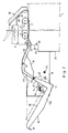
- the carrier 12a In the position of the receiving tray 8 represented in Fig. 1, the carrier 12a is situated above the pivot 9 and the receiving tray rests by an end 25 of the carrier 12a on part 23 of abutment 20. That side of the L-shaped body 12 which faces the pivot 9 is formed by a support surface 30 on the long leg 12a and an abutment surface 31 on the short leg 12b, the said abutment surface 31 forming an angle of 90° with support surface 30.
- a support surface 26 is situated opposite support surface 30 on the long leg 12a.
- a bent guide element 33 is connected at one end by a hinge 34 to the end of the short leg 12b. In the position of the receiving tray represented in Fig. 1, guide element 33 rests on a rod 35 secured between the frame plates 10.
- Guide element 33 has a profiled plate 36 at the underside, which plate on rotation of the receiving tray from the position represented in Fig. 1 co-operates with rod 35 as will be explained hereinafter.
- auxiliary member 38 which is used when processing computer forms.
- auxiliary member 38 is provided with a pin 39 which fits in a hole 40 in guide element 33 for detachably securing the auxiliary member 38 on guide element 33.
- the copying machine is arranged as follows for processing computer forms: by pressing on the receiving tray at place indicated by arrow 41 body 12 rotates about pivot 9.
- hinge 34 describes a circular path indicated by reference 42.
- the profiled plate 36 slides over rod 35, the end 43 of guide element 33 describing a path denoted by line 44 and the end 43 coming to rest on abutment part 21.
- the profiled plate 36 is free of rod 35 and guide element 33 rotates about the end 43 resting on abutment part 21.
- conveyor belt 6 feeds the computer form from the stock over the exposure window 2.
- the computer form then moves over guide element 33 into receiving tray 8, the leading edge of the computer form arriving at the angle between the support surface 30 and the abutment surface 31 and the computer form then being placed in the receiving tray in zig-zag folded form.
- the front edge and the following even folding edges must be able to move freely downwards over a distance of 65 mm minimum along the side abutment formed by surfaces 31 and 45.
- the receiving tray should have a depth of 165 mm.
- the latter can readily be reset to the original position, by first placing the inlet guide 38 on the sheet guide 33 and then pressing on the receiving tray at the place denoted by arrow 49 until the position represented in Fig. 1 again is obtained.
Landscapes
- Physics & Mathematics (AREA)
- General Physics & Mathematics (AREA)
- Pile Receivers (AREA)
- Manual Feeding Of Sheets (AREA)
Claims (5)
- Sammelbrett für blattförmiges Material, Insbesondere für aus einem Kopiergerät kommendes Material, mit einer Stütze (12), die um eine Gelenkachse (9) drehbar ist und zwei entgegengesetzt angeordnete, zu der Gelenkachse (9) parallele Stützflächen aufweist und in der Lage ist, zwei Positionen einzunehmen, nämlich eine erste Position, in der eine der Stützflächen blattförmiges Material aufnehmen kann, und eine zweite Position, in der die andere Stützfläche blattförmiges Material aufnehmen kann, dadurch gekennzeichnet, daß die kürzesten Abstände zwischen jeder der Stützflächen (26,30) und der Gelenkachse (9) verschieden sind.
- Sammelbrett nach Anspruch 1, dadurch gekennzeichnet, daß der kürzeste Abstand zwischen der Gelenkachse (9) und einem Rand einer Stützfläche kleiner ist als der kürzeste Abstand zwischen der Gelenkachse und dem entgegengesetzten Rand derselben Stützfläche (30).
- Sammelbrett nach Anspruch 2, dadurch gekennzeichnet, daß die Stütze (12) an der Stützfläche, die der Gelenkachse (9) am nächsten liegt, mit einem Blatt-Anschlag (12b,31) versehen ist.
- Sammelbrett nach Anspruch 3, dadurch gekennzeichnet, daß ein gekrümmtes Führungselement (33) vorgesehen ist, das durch ein Scharnier (34) mit dem Ende des Blatt-Anschlags (12b,31) verbunden ist, der dem mit der Stütze (12) verbundenen Rand des Blatt-Anschlags (12b,31) entgegengesetzt ist, welches Führungselement (33) um das Scharnier (34) aus einer ersten Position, in der das Führungselement (33) sich in dem durch den Blatt-Anschlag (31) und die angrenzende Stützfläche (30) begrenzten Raum befindet, in eine zweite Position schwenken kann, in der das Führungselement (33) mit dem Blatt-Anschlag (12b,31) fluchtet.
- Sammelbrett nach Anspruch 4, dadurch gekennzeichnet, daß das Führungselement (33) mit einer Platte mit einem profilierten Rand (36) versehen ist, der sich auf einer Stange (35) abstützen kann und sicherstellt, daß bei der Drehung der Stutze (12) aus ihrer ersten Position in ihre zweite Position das Führungselement (33) im wesentlichen parallel zu sich selbst aus seiner ersten Position, in der es sich unterhalb der Stützfläche (26,30) befindet, in seine zweite Position bewegt wird.
Applications Claiming Priority (2)
| Application Number | Priority Date | Filing Date | Title |
|---|---|---|---|
| NL8801610A NL8801610A (nl) | 1988-06-24 | 1988-06-24 | Opvangbak voor bladvormig materiaal, in het bijzonder uit een kopieerapparaat komend materiaal. |
| NL8801610 | 1988-06-24 |
Publications (2)
| Publication Number | Publication Date |
|---|---|
| EP0347973A1 EP0347973A1 (de) | 1989-12-27 |
| EP0347973B1 true EP0347973B1 (de) | 1994-01-26 |
Family
ID=19852517
Family Applications (1)
| Application Number | Title | Priority Date | Filing Date |
|---|---|---|---|
| EP89201516A Expired - Lifetime EP0347973B1 (de) | 1988-06-24 | 1989-06-12 | Sammelbrett für blattförmiges Material, insbesondere für aus einem Kopiergerät kommendes Material |
Country Status (6)
| Country | Link |
|---|---|
| US (1) | US4993701A (de) |
| EP (1) | EP0347973B1 (de) |
| JP (1) | JP2740267B2 (de) |
| KR (1) | KR0133925B1 (de) |
| DE (1) | DE68912658T2 (de) |
| NL (1) | NL8801610A (de) |
Families Citing this family (6)
| Publication number | Priority date | Publication date | Assignee | Title |
|---|---|---|---|---|
| US5110111A (en) * | 1990-02-28 | 1992-05-05 | Hewlett-Packard Company | Apparatus including a u-shaped bin having a bar grid network for uniformly stacking cut sheets of printed media |
| US5081487A (en) * | 1991-01-25 | 1992-01-14 | Xerox Corporation | Cut sheet and computer form document output tray unit |
| JPH06324540A (ja) * | 1993-05-12 | 1994-11-25 | Konica Corp | 自動原稿送り装置を備えた複写機 |
| DE10043392A1 (de) * | 2000-09-04 | 2002-03-14 | Heidelberger Druckmasch Ag | Vorrichtung zum stapelweisen Ablegen und Ausrichten von Blattgut |
| NL1027387C2 (nl) * | 2004-11-01 | 2006-05-03 | Oce Tech Bv | Vellenopvanginrichting. |
| US7237969B2 (en) * | 2005-10-05 | 2007-07-03 | Xerox Corporation | Dual output tray |
Family Cites Families (5)
| Publication number | Priority date | Publication date | Assignee | Title |
|---|---|---|---|---|
| US4191467A (en) * | 1979-04-04 | 1980-03-04 | Xerox Corporation | Dual mode catch tray |
| JPS5917452A (ja) * | 1982-07-19 | 1984-01-28 | Nippon Telegr & Teleph Corp <Ntt> | フアクシミリ装置用スタツカ |
| GB8515939D0 (en) * | 1985-06-24 | 1985-07-24 | Xerox Corp | Restacking apparatus |
| US4635916A (en) * | 1985-10-15 | 1987-01-13 | Xerox Corporation | Dual-mode copier document feeder and computer forms web restacker |
| JPS6317766A (ja) * | 1986-07-09 | 1988-01-25 | Canon Inc | シ−ト排出トレ−装置 |
-
1988
- 1988-06-24 NL NL8801610A patent/NL8801610A/nl not_active Application Discontinuation
-
1989
- 1989-05-24 KR KR1019890006917A patent/KR0133925B1/ko not_active Expired - Fee Related
- 1989-06-12 DE DE68912658T patent/DE68912658T2/de not_active Expired - Fee Related
- 1989-06-12 EP EP89201516A patent/EP0347973B1/de not_active Expired - Lifetime
- 1989-06-16 JP JP1154371A patent/JP2740267B2/ja not_active Expired - Fee Related
- 1989-06-19 US US07/367,974 patent/US4993701A/en not_active Expired - Lifetime
Also Published As
| Publication number | Publication date |
|---|---|
| US4993701A (en) | 1991-02-19 |
| JPH0233051A (ja) | 1990-02-02 |
| EP0347973A1 (de) | 1989-12-27 |
| DE68912658T2 (de) | 1994-06-23 |
| KR900000737A (ko) | 1990-01-31 |
| NL8801610A (nl) | 1990-01-16 |
| KR0133925B1 (ko) | 1998-04-25 |
| JP2740267B2 (ja) | 1998-04-15 |
| DE68912658D1 (de) | 1994-03-10 |
Similar Documents
| Publication | Publication Date | Title |
|---|---|---|
| US4372547A (en) | Sheet feed apparatus | |
| EP0574008B1 (de) | Automatisches Dokumentenfördergerät | |
| EP0347973B1 (de) | Sammelbrett für blattförmiges Material, insbesondere für aus einem Kopiergerät kommendes Material | |
| US4406448A (en) | Paper cassette | |
| US4395034A (en) | Sheet feeding device | |
| JP3050635B2 (ja) | 画像形成装置 | |
| KR19980029961A (ko) | 사무자동화기기에 있어서 용지급지대의 절환장치 | |
| US3630515A (en) | Document-handling apparatus | |
| US7862015B2 (en) | Sheet folding device, and paper post-processing device and image forming system provided therewith | |
| US5144386A (en) | Image-forming apparatus having a manual paper supply port located above a paper discharging port | |
| JPH05294471A (ja) | シート積載装置 | |
| US5228671A (en) | Sheet feeder with single sheet bypass | |
| EP0572221B1 (de) | Stapelvorrichtung mit hoher Kapazität für Umschläge | |
| US4354672A (en) | Sheet stacking and aligning apparatus | |
| JPH03272923A (ja) | 給紙装置 | |
| US5363998A (en) | Restacking tray for fan fold paper feeder | |
| US4265442A (en) | Cassette locking and alignment assembly | |
| US5074543A (en) | Hopper assembly for selectively restacking both individual originals and fan-folded originals received from a document reproduction machine | |
| JPH0544346Y2 (de) | ||
| JPH07115789B2 (ja) | 原稿案内装置 | |
| EP0371409B1 (de) | Gerät zur manuellen Betätigung der Zufuhr eines Blattes | |
| JPS6312107Y2 (de) | ||
| JPH0752118Y2 (ja) | 給紙装置 | |
| JPH0748062A (ja) | シート処理装置 | |
| JPH0242679Y2 (de) |
Legal Events
| Date | Code | Title | Description |
|---|---|---|---|
| PUAI | Public reference made under article 153(3) epc to a published international application that has entered the european phase |
Free format text: ORIGINAL CODE: 0009012 |
|
| AK | Designated contracting states |
Kind code of ref document: A1 Designated state(s): DE FR GB IT NL SE |
|
| 17P | Request for examination filed |
Effective date: 19900525 |
|
| 17Q | First examination report despatched |
Effective date: 19920701 |
|
| GRAA | (expected) grant |
Free format text: ORIGINAL CODE: 0009210 |
|
| AK | Designated contracting states |
Kind code of ref document: B1 Designated state(s): DE FR GB IT NL SE |
|
| REF | Corresponds to: |
Ref document number: 68912658 Country of ref document: DE Date of ref document: 19940310 |
|
| ET | Fr: translation filed | ||
| ITF | It: translation for a ep patent filed | ||
| ET1 | Fr: translation filed ** revision of the translation of the patent or the claims | ||
| PLBE | No opposition filed within time limit |
Free format text: ORIGINAL CODE: 0009261 |
|
| STAA | Information on the status of an ep patent application or granted ep patent |
Free format text: STATUS: NO OPPOSITION FILED WITHIN TIME LIMIT |
|
| 26N | No opposition filed | ||
| EAL | Se: european patent in force in sweden |
Ref document number: 89201516.5 |
|
| NLT1 | Nl: modifications of names registered in virtue of documents presented to the patent office pursuant to art. 16 a, paragraph 1 |
Owner name: OCE-TECHNOLOGIES B.V. |
|
| REG | Reference to a national code |
Ref country code: GB Ref legal event code: IF02 |
|
| PGFP | Annual fee paid to national office [announced via postgrant information from national office to epo] |
Ref country code: FR Payment date: 20030512 Year of fee payment: 15 |
|
| PGFP | Annual fee paid to national office [announced via postgrant information from national office to epo] |
Ref country code: GB Payment date: 20030516 Year of fee payment: 15 |
|
| PGFP | Annual fee paid to national office [announced via postgrant information from national office to epo] |
Ref country code: SE Payment date: 20030527 Year of fee payment: 15 Ref country code: DE Payment date: 20030527 Year of fee payment: 15 |
|
| PG25 | Lapsed in a contracting state [announced via postgrant information from national office to epo] |
Ref country code: GB Free format text: LAPSE BECAUSE OF NON-PAYMENT OF DUE FEES Effective date: 20040612 |
|
| PG25 | Lapsed in a contracting state [announced via postgrant information from national office to epo] |
Ref country code: SE Free format text: LAPSE BECAUSE OF NON-PAYMENT OF DUE FEES Effective date: 20040613 |
|
| PGFP | Annual fee paid to national office [announced via postgrant information from national office to epo] |
Ref country code: NL Payment date: 20040623 Year of fee payment: 16 |
|
| PG25 | Lapsed in a contracting state [announced via postgrant information from national office to epo] |
Ref country code: DE Free format text: LAPSE BECAUSE OF NON-PAYMENT OF DUE FEES Effective date: 20050101 |
|
| EUG | Se: european patent has lapsed | ||
| GBPC | Gb: european patent ceased through non-payment of renewal fee |
Effective date: 20040612 |
|
| EUG | Se: european patent has lapsed | ||
| PG25 | Lapsed in a contracting state [announced via postgrant information from national office to epo] |
Ref country code: FR Free format text: LAPSE BECAUSE OF NON-PAYMENT OF DUE FEES Effective date: 20050228 |
|
| REG | Reference to a national code |
Ref country code: FR Ref legal event code: ST |
|
| PG25 | Lapsed in a contracting state [announced via postgrant information from national office to epo] |
Ref country code: IT Free format text: LAPSE BECAUSE OF NON-PAYMENT OF DUE FEES Effective date: 20050612 |
|
| PG25 | Lapsed in a contracting state [announced via postgrant information from national office to epo] |
Ref country code: NL Free format text: LAPSE BECAUSE OF NON-PAYMENT OF DUE FEES Effective date: 20060101 |
|
| NLV4 | Nl: lapsed or anulled due to non-payment of the annual fee |
Effective date: 20060101 |