EP0347594B1 - Drive system for a vehicle - Google Patents
Drive system for a vehicle Download PDFInfo
- Publication number
- EP0347594B1 EP0347594B1 EP89109188A EP89109188A EP0347594B1 EP 0347594 B1 EP0347594 B1 EP 0347594B1 EP 89109188 A EP89109188 A EP 89109188A EP 89109188 A EP89109188 A EP 89109188A EP 0347594 B1 EP0347594 B1 EP 0347594B1
- Authority
- EP
- European Patent Office
- Prior art keywords
- operating range
- main shaft
- output
- hydroconverter
- gear unit
- Prior art date
- Legal status (The legal status is an assumption and is not a legal conclusion. Google has not performed a legal analysis and makes no representation as to the accuracy of the status listed.)
- Expired - Lifetime
Links
Images
Classifications
-
- F—MECHANICAL ENGINEERING; LIGHTING; HEATING; WEAPONS; BLASTING
- F16—ENGINEERING ELEMENTS AND UNITS; GENERAL MEASURES FOR PRODUCING AND MAINTAINING EFFECTIVE FUNCTIONING OF MACHINES OR INSTALLATIONS; THERMAL INSULATION IN GENERAL
- F16H—GEARING
- F16H47/00—Combinations of mechanical gearing with fluid clutches or fluid gearing
- F16H47/02—Combinations of mechanical gearing with fluid clutches or fluid gearing the fluid gearing being of the volumetric type
- F16H47/04—Combinations of mechanical gearing with fluid clutches or fluid gearing the fluid gearing being of the volumetric type the mechanical gearing being of the type with members having orbital motion
-
- F—MECHANICAL ENGINEERING; LIGHTING; HEATING; WEAPONS; BLASTING
- F16—ENGINEERING ELEMENTS AND UNITS; GENERAL MEASURES FOR PRODUCING AND MAINTAINING EFFECTIVE FUNCTIONING OF MACHINES OR INSTALLATIONS; THERMAL INSULATION IN GENERAL
- F16H—GEARING
- F16H37/00—Combinations of mechanical gearings, not provided for in groups F16H1/00 - F16H35/00
- F16H37/02—Combinations of mechanical gearings, not provided for in groups F16H1/00 - F16H35/00 comprising essentially only toothed or friction gearings
- F16H37/06—Combinations of mechanical gearings, not provided for in groups F16H1/00 - F16H35/00 comprising essentially only toothed or friction gearings with a plurality of driving or driven shafts; with arrangements for dividing torque between two or more intermediate shafts
- F16H37/08—Combinations of mechanical gearings, not provided for in groups F16H1/00 - F16H35/00 comprising essentially only toothed or friction gearings with a plurality of driving or driven shafts; with arrangements for dividing torque between two or more intermediate shafts with differential gearing
- F16H37/0833—Combinations of mechanical gearings, not provided for in groups F16H1/00 - F16H35/00 comprising essentially only toothed or friction gearings with a plurality of driving or driven shafts; with arrangements for dividing torque between two or more intermediate shafts with differential gearing with arrangements for dividing torque between two or more intermediate shafts, i.e. with two or more internal power paths
- F16H37/084—Combinations of mechanical gearings, not provided for in groups F16H1/00 - F16H35/00 comprising essentially only toothed or friction gearings with a plurality of driving or driven shafts; with arrangements for dividing torque between two or more intermediate shafts with differential gearing with arrangements for dividing torque between two or more intermediate shafts, i.e. with two or more internal power paths at least one power path being a continuously variable transmission, i.e. CVT
- F16H2037/0866—Power split variators with distributing differentials, with the output of the CVT connected or connectable to the output shaft
-
- F—MECHANICAL ENGINEERING; LIGHTING; HEATING; WEAPONS; BLASTING
- F16—ENGINEERING ELEMENTS AND UNITS; GENERAL MEASURES FOR PRODUCING AND MAINTAINING EFFECTIVE FUNCTIONING OF MACHINES OR INSTALLATIONS; THERMAL INSULATION IN GENERAL
- F16H—GEARING
- F16H37/00—Combinations of mechanical gearings, not provided for in groups F16H1/00 - F16H35/00
- F16H37/02—Combinations of mechanical gearings, not provided for in groups F16H1/00 - F16H35/00 comprising essentially only toothed or friction gearings
- F16H37/06—Combinations of mechanical gearings, not provided for in groups F16H1/00 - F16H35/00 comprising essentially only toothed or friction gearings with a plurality of driving or driven shafts; with arrangements for dividing torque between two or more intermediate shafts
- F16H37/08—Combinations of mechanical gearings, not provided for in groups F16H1/00 - F16H35/00 comprising essentially only toothed or friction gearings with a plurality of driving or driven shafts; with arrangements for dividing torque between two or more intermediate shafts with differential gearing
- F16H37/0833—Combinations of mechanical gearings, not provided for in groups F16H1/00 - F16H35/00 comprising essentially only toothed or friction gearings with a plurality of driving or driven shafts; with arrangements for dividing torque between two or more intermediate shafts with differential gearing with arrangements for dividing torque between two or more intermediate shafts, i.e. with two or more internal power paths
- F16H37/084—Combinations of mechanical gearings, not provided for in groups F16H1/00 - F16H35/00 comprising essentially only toothed or friction gearings with a plurality of driving or driven shafts; with arrangements for dividing torque between two or more intermediate shafts with differential gearing with arrangements for dividing torque between two or more intermediate shafts, i.e. with two or more internal power paths at least one power path being a continuously variable transmission, i.e. CVT
- F16H2037/088—Power split variators with summing differentials, with the input of the CVT connected or connectable to the input shaft
-
- F—MECHANICAL ENGINEERING; LIGHTING; HEATING; WEAPONS; BLASTING
- F16—ENGINEERING ELEMENTS AND UNITS; GENERAL MEASURES FOR PRODUCING AND MAINTAINING EFFECTIVE FUNCTIONING OF MACHINES OR INSTALLATIONS; THERMAL INSULATION IN GENERAL
- F16H—GEARING
- F16H37/00—Combinations of mechanical gearings, not provided for in groups F16H1/00 - F16H35/00
- F16H37/02—Combinations of mechanical gearings, not provided for in groups F16H1/00 - F16H35/00 comprising essentially only toothed or friction gearings
- F16H37/06—Combinations of mechanical gearings, not provided for in groups F16H1/00 - F16H35/00 comprising essentially only toothed or friction gearings with a plurality of driving or driven shafts; with arrangements for dividing torque between two or more intermediate shafts
- F16H37/08—Combinations of mechanical gearings, not provided for in groups F16H1/00 - F16H35/00 comprising essentially only toothed or friction gearings with a plurality of driving or driven shafts; with arrangements for dividing torque between two or more intermediate shafts with differential gearing
- F16H37/10—Combinations of mechanical gearings, not provided for in groups F16H1/00 - F16H35/00 comprising essentially only toothed or friction gearings with a plurality of driving or driven shafts; with arrangements for dividing torque between two or more intermediate shafts with differential gearing at both ends of intermediate shafts
- F16H2037/103—Power split variators with each end of the CVT connected or connectable to a Ravigneaux set
-
- Y—GENERAL TAGGING OF NEW TECHNOLOGICAL DEVELOPMENTS; GENERAL TAGGING OF CROSS-SECTIONAL TECHNOLOGIES SPANNING OVER SEVERAL SECTIONS OF THE IPC; TECHNICAL SUBJECTS COVERED BY FORMER USPC CROSS-REFERENCE ART COLLECTIONS [XRACs] AND DIGESTS
- Y10—TECHNICAL SUBJECTS COVERED BY FORMER USPC
- Y10T—TECHNICAL SUBJECTS COVERED BY FORMER US CLASSIFICATION
- Y10T74/00—Machine element or mechanism
- Y10T74/19—Gearing
- Y10T74/19023—Plural power paths to and/or from gearing
- Y10T74/19037—One path includes fluid drive
Definitions
- the invention relates to a drive device of a vehicle with a hydrostatic-mechanical power split transmission with features of the type specified in the preamble of claim 1.
- a drive device with such features is known for example from DE-PS 2904572.
- vehicle drives realized according to this, a hydromechanical power split transmission with two hydraulic converters in the form of adjustable hydraulic machines that can be operated as a motor or pumps was used, each of which can transmit a corner power in the order of magnitude of the power of the drive motor.
- This drive constellation enables a torque increase of approx. Factor 5 to be achieved between the drive motor and the axle drive train.
- the aforementioned increase in torque is not sufficient to get a sufficient overall range of conversion.
- a sufficient total range of conversion would be, for example, only with an increase in torque in heavy chain or wheeled vehicles given by factor 10 at full engine power.
- This problem could be remedied, for example, by using more powerful hydraulic converters.
- Such larger hydraulic converters would not only increase the overall size of the power split transmission, but rather the hydraulic system parts such as lines, control elements, valves and the like would also have to be designed for the larger fluid throughput with increased power, which would obviously make the power split gear much more expensive.
- the necessary installation space is generally not available for these measures.
- the power split transmission is designed by adding simple gear trains and switchable clutches to the known structure of the same for extreme overdrive operation with a speed ratio between the output-side and the input-side main shaft of up to approx. 2.
- this power split transmission is designed in such a way that that of the two hydraulic converters, which is connected in the first and second operating range to the ring gear of the planetary differential via the switchable clutch SK3, during the transition from the second operating range to at least one further one in overdrive mode leading operating area by actuating switchable clutches SK3, SK4, SK5 separated from its current drive connection and at synchronous speed connected to one of the two main shafts, i.e. either the input side or the output side main shaft.
- the operating area going into overdrive mode is preferably divided into two defined partial areas such that a third operating area with n output : n input between approximately 0.8 and approximately 1.4 and a fourth operating area with n output : n input between about 1.5 and about 2.
- the drive device according to the invention is used in a very heavy chain or wheeled vehicle, then it proves to be expedient to drive the said hydraulic converter from the ring gear of the planetary differential gear in the transition from the second to the third operating range disconnect and connect to the input side main shaft of the power split transmission. If the maximum speed of the drive motor remains constant and the speed of the hydraulic converter connected to the main shaft on the input side remains constant and the speed of the other hydraulic converter acting as a pump decreases, the speed of the main shaft on the output side of the power split transmission can increase in the overdrive range.
- the drive device according to the invention is used in a passenger car, in contrast to very heavy vehicles, it is more expedient in this case to drive the said hydraulic converter from the ring gear of the Separate planetary differential gear and connect to the output side main shaft of the power split transmission.
- This has the advantage that there is no reactive power in the third operating range and the hydrostatic part of the total power only increases to less than 50%.
- a drive motor for example a diesel engine
- 2 a hydrostatic-mechanical power split transmission
- 3 a distributor and / or steering gear
- 3/1 or 3/2 the axle shafts outgoing on both sides of the latter and with 3/3 or 3/4 the drive wheels connected to the latter.
- These drive wheels are the chain wheels driving the chains in the case of a tracked vehicle and the driven wheels thereof in the case of wheeled vehicles.
- the power split transmission 2 has a planetary differential 4 and at least two hydraulic converters 5, 6.
- the latter are adjustable hydraulic machines that can be operated in both directions as a motor or pump and are connected to one another via hydraulic lines 7, 8.
- the main shaft 9 on the input side can either be directly coupled to the crankshaft 1/1 or, as shown in the figures, be connected to the crankshaft 1/1 of the drive motor 1 via a reduction gear 1/2.
- the connecting shaft 11 leading to the distributor and / or steering gear 3 is connected to the main shaft 10 on the output side.
- the reduction gear 1/2 serves to avoid excessive speeds in the power split transmission 2.
- the planetary differential 4 in the illustrated embodiment includes a large sun gear 12 fixedly connected to the input-side main shaft 9, a small sun gear 13, several each rotatably mounted on a web 14 fixedly connected to the output-side main shaft 10 Double planetary gears 15, 16, a hollow shaft 17 fixedly coaxially connected to the web 14, and a ring gear 18.
- the latter has an internal toothing 19 with which the toothing of the planet gears 16 mesh.
- the small sun gear is non-rotatably connected to a hollow shaft 20 which is mounted on the main shaft 9 on the input side, and also carries a gear wheel 21 and supports the hollow shaft 17.
- a switchable coupling is designated, via the shift sleeve 39 a connection between the ring gear 18 and a gear 22 can be made or released.
- This gear 22 forms, together with a gear 41 fixedly arranged on a secondary shaft 40 and a gear 23, which is firmly seated on the shaft 24, the drive connection to the hydraulic converter 5.
- the speed of the main shaft 10 on the output side adds up from the speeds of the large sun gear 12 and the ring gear 18, which determine the rotational speed of the planet gears 15 and the web 14.
- the hydraulic converter 5 effects its speed and direction of rotation through its speed and direction of rotation via the gears 23, 41, 22 and the ring gear 18.
- the gear 21 seated on the hollow shaft 20 meshes with a gear 26 which is rotatably but axially secured on a further auxiliary shaft 25.
- the latter carries a driving disk 26 and is a switchable sleeve 28 of a switchable sleeve 28 which is axially displaceable on a driver 38 arranged on the auxiliary shaft 25
- Coupling SK1 with the auxiliary shaft 25 can be brought into or out of the drive connection.
- the auxiliary shaft 25 can directly establish the mechanical connection between the planetary differential 4 and the hydraulic converter 6, in which case the latter would then be connected directly to the auxiliary shaft with its shaft.
- auxiliary shaft 25 rotatably carries a gear 29 which meshes as part of a gear ratio to the hydraulic converter 6 with a gear 30 which is non-rotatably seated on a shaft 31 which produces the mechanical connection to the hydraulic converter 6.
- the hydraulic converter 6 can optionally be connected to the output-side main shaft 10 or the small sun gear 13 via two different gear ratios.
- the other of the two gear ratios is realized in that a drive wheel 32 is arranged in a rotationally fixed manner with the hollow shaft 17, which is fixedly connected to the web 14, which carries a shift sleeve 33 which can be displaced axially between a non-driven O position and the drive transmission position as part of a switchable clutch SK2.
- the driving wheel 32 is operatively connected via the gearshift sleeve 33 of the clutch SK2 to a driving wheel 34, which is fixedly connected to a gear 36 via a hub 35 mounted on the hollow shaft 17, which in turn is connected to a gear 37 arranged in a rotationally fixed manner on the auxiliary shaft 25 combs.
- the gear ratio 37 / gear 36 carries, for example, 1: 4.5 and is greater than the gear ratio of gear 26 / gear 21, for example 1: 1.5.
- the aforementioned first gear ratio between the output-side main shaft 10 and the hydraulic converter 6 is effective in a first operating range of the vehicle, in which a speed ratio between the output-side main shaft 10 and the input-side main shaft 9 with n output : n input ⁇ is approximately 50%.
- the shift sleeve 33 of the clutch SK2 is in operative connection with the drive plate 34, ie SK2 is closed.
- the hydraulic converter 6 is connected via the shaft 31, the gears 30, 29, the auxiliary shaft 25 and the gears 37, 36 to the hollow shaft 17 and thus to the carrier 14 of the planetary differential gear 4.
- the hydraulic converter 5 works in this case with a direction of rotation of the ring gear 18 in reverse to the direction of rotation of the large sun gear 12 driven on the motor side as a pump and supplies the converted power to the hydraulic converter 6.
- the latter works as a motor and drives the shaft 31, thereby providing power via the aforementioned transmission path is transmitted to the main shaft 10 on the output side.
- the power split transmission 2 is also designed for extreme overdrive operation with a speed ratio between the output-side main shaft 10 and the input-side main shaft 9 with n output : n input > approximately 1.5 to approximately 2.
- This operating area which goes into overdrive mode, is preferably subdivided into two sections, such that a third operating area with n output : n input ranges from approx. 80% to approx. 140% and a fourth operating area with n output : n input of approx 140% to 200% is enough.
- Overdrive operation can also be divided into three areas.
- Said overdrive operation can be implemented by adding relatively simple gear trains and switchable clutches to the structure of the power split transmission described above.
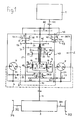
- FIG. 1 it can be a gear 42 which is firmly seated on the input-side main shaft 9 and a gear 43 which meshes with it and which is loosely rotatable but axially secured on the first auxiliary shaft 40 and a drive plate 44 carries, via which it can be coupled to the auxiliary shaft 40 through the shift sleeve 45 of a switchable clutch SK4.
- the shift sleeve 45 is axially displaceable on a drive plate 46 arranged fixedly on the auxiliary shaft 40 from a drive-free zero position in coupling connection with the drive plate 44 and back.
- Such a drive device is well suited for use in very heavy vehicles, such as tracked vehicles or heavy-duty vehicles.
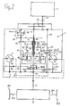
- the additional organs that enable overdrive operation can also be a toothing 47 that rotates with the output-side main shaft 10 and a meshing gear 48 with a larger diameter that meshes loosely but axially secured the first auxiliary shaft 40 is mounted and carries a drive plate 49, via which it can be coupled to the auxiliary shaft 40 through the shift sleeve 50 of a switchable clutch SK5.
- the toothing 47 can be part of a gear wheel which is fixedly arranged either on the hollow shaft 17, the web 14 or the main shaft 10 on the output side.
- the shift sleeve 50 of the clutch SK5 is axial on a drive plate 51 fixedly arranged on the auxiliary shaft 40 Slidable from a zero drive position in coupling connection with the drive plate 49 and back.
- This drive device is well suited for use in passenger cars.
- This variant according to FIG. 2 is therefore particularly suitable for vehicles which are operated a lot in the third operating range, that is to say the lower overdrive range, and little or rarely in the upper overdrive range.
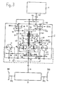
- the drive device according to FIG. 3 can thus be used in general and with particular advantage in all those vehicles which are operated a lot and in the entire overdrive range.
Description
Die Erfindung betrifft eine Antriebseinrichtung eines Fahrzeuges mit einem hydrostatisch-mechanischen Leistungsverzweigungsgetriebe mit Merkmalen der im Oberbegriff des Anspruches 1 angegebenen Art.The invention relates to a drive device of a vehicle with a hydrostatic-mechanical power split transmission with features of the type specified in the preamble of
Eine Antriebseinrichtung mit solchen Merkmalen ist beispielsweise aus der DE-PS 2904572 bekannt. Bei hiernach realisierten Fahrzeug-Antrieben kam ein hydromechanisches Leistungsverzweigungsgetriebe mit zwei Hydrowandlern in Form von verstellbaren, als Motor oder Pumpen betreibbaren Hydromaschinen zur Anwendung, von denen jeder eine Eckleistung in der Größenordnung der Leistung des Antriebsmotors übertragen kann. Durch diese Antriebskonstellation ist zwischen Antriebsmotor und Achsantriebsstrang eine Momentenerhöhung um ca. Faktor 5 erzielbar.A drive device with such features is known for example from DE-PS 2904572. In the vehicle drives realized according to this, a hydromechanical power split transmission with two hydraulic converters in the form of adjustable hydraulic machines that can be operated as a motor or pumps was used, each of which can transmit a corner power in the order of magnitude of the power of the drive motor. This drive constellation enables a torque increase of approx.
Diese bekannte Lösung läßt einen Betrieb in einem breiten Overdrive-Bereich zu, allerdings bei abnehmender Motor drehzahl und fallender Getriebeabtriebsdrehzahl sowie unter Inkaufnahme einer ab einem Drehzahlverhältnis von nAusgang: nEingang > ca. 1,5 auftretenden und zunehmenden Blindleistung, das heißt sinkendem Wirkungsgrad. Letzteres wirkt sich insbesondere bei Verwendung der Antriebseinrichtung als Pkw-Antrieb aufgrund der großen Drehzahlspanne des dort verwendeten Antriebsmotors negativ aus.This known solution allows operation in a wide overdrive range, but with a decreasing engine speed and falling transmission output speed and with the acceptance of an increasing and occurring reactive power from a speed ratio of n output : n input > approx.1.5, i.e. decreasing efficiency . The latter has a negative effect in particular when the drive device is used as a car drive due to the large speed range of the drive motor used there.
Bei verschiedenen Einsatzfällen reicht die vorgenannte Momentenerhöhung (um Faktor 5) nicht aus, um einen ausreichenden Gesamtwandlungsbereich zu bekommen. Ein ausreichender Gesamtwandlungsbereich wäre bei Schwerst-Ketten- oder -Radfahrzeugen beispielsweise erst durch eine Momentenerhöhung um Faktor 10 bei voller Motorleistung gegeben. Diesem Problem könnte beispielsweise durch die Verwendung leistungsstärkerer Hydrowandler abgeholfen werden. Solche größeren Hydrowandler würden aber nicht nur das Leistungsverzweigungsgetriebe insgesamt räumlich vergrößern, vielmehr müßten auch die hydraulischen Anlagenteile wie Leitungen, Steuerorgane, Ventile und dergleichen auf den größeren Fluiddurchsatz mit erhöhter Leistung ausgelegt sein, was ersichtlicherweise das Leistungsverzweigungsgetriebe in erheblichem Maß verteuern würde. Außerdem steht für diese Maßnahmen in der Regel nicht der notwendige Bauraum zur Verfügung.In various applications, the aforementioned increase in torque (by a factor of 5) is not sufficient to get a sufficient overall range of conversion. A sufficient total range of conversion would be, for example, only with an increase in torque in heavy chain or wheeled vehicles given by
Es ist daher Aufgabe der Erfindung, eine Antriebseinrichtung der eingangs genannten Art so umzugestalten, daß trotz Verwendung leistungsgleicher Hydrowandler und des gleichen vierwelligen Planetendifferentialgetriebes wie bisher eine Erweiterung des effektiv verfügbaren Overdrive-Bereiches zumindest ohne Zwangsreduzierung der Abtriebsdrehzahl des hydrostatisch-mechanischen Leistungsverzweigungsgetriebes bei steigendem Drehzahlverhältnis nAusgang: nEingang und eine Vermeidung bzw. zumindest Reduzierung der hydrostatischen Blindleistung am Ende des Overdrive-Bereiches erzielbar ist.It is therefore an object of the invention to convert a drive device of the type mentioned in such a way that, despite the use of hydraulic converters of the same power and the same four-shaft planetary differential gear as before, an expansion of the effectively available overdrive range, at least without forced reduction of the output speed of the hydrostatic-mechanical power split transmission, with an increasing speed ratio n Output : n input and avoidance or at least reduction of the hydrostatic reactive power at the end of the overdrive range can be achieved.
Diese Aufgabe ist bei einer Antriebseinrichtung der gattungsgemäßen Art erfindungsgemäß durch deren weitere Ausgestaltung entsprechend den kennzeichnenden Merkmalen des Anspruches 1 gelöst.This object is achieved according to the invention in a drive device of the generic type by its further configuration in accordance with the characterizing features of
Grundsätzlich ist dabei das Leistungsverzweigungsgetriebe durch Hinzufügen einfacher Getriebezüge und schaltbarer Kupplungen zu dem bekannten Aufbau desselben für einen extremen Overdrive-Betrieb mit einem Drehzahlverhältnis zwischen ausgangsseitiger und eingangsseitiger Hauptwelle von bis zu ca. 2 ausgelegt. Regelungstechnisch wird dabei derart auf dieses so gestaltete Leistungsverzweigungsgetriebe eingewirkt, daß jener der beiden Hydrowandler, der im ersten und zweiten Betriebsbereich mit dem Hohlrad des Planetendifferentiales über die schaltbare Kupplung SK3 verbunden ist, beim Übergang vom zweiten Betriebsbereich in wenigstens einen weiteren in den Overdrive-Betrieb führenden Betriebsbereich durch Betätigung schaltbarer Kupplungen SK3, SK4, SK5 von seiner momentanen Antriebsverbindung getrennt und bei Synchrondrehzahl getrieblich mit einer der beiden Hauptwellen, also entweder der eingangsseitigen oder ausgangsseitigen Hauptwelle verbunden wird.Basically, the power split transmission is designed by adding simple gear trains and switchable clutches to the known structure of the same for extreme overdrive operation with a speed ratio between the output-side and the input-side main shaft of up to approx. 2. In terms of control technology, this power split transmission is designed in such a way that that of the two hydraulic converters, which is connected in the first and second operating range to the ring gear of the planetary differential via the switchable clutch SK3, during the transition from the second operating range to at least one further one in overdrive mode leading operating area by actuating switchable clutches SK3, SK4, SK5 separated from its current drive connection and at synchronous speed connected to one of the two main shafts, i.e. either the input side or the output side main shaft.
Vorzugsweise ist der in den Overdrive-Betrieb gehende Betriebsbereich in zwei definierte Teilbereiche untergliedert, dergestalt, daß ein dritter Betriebsbereich mit nAusgang: nEingang zwischen ca. 0,8 und ca. 1,4 und ein vierter Betriebsbereich mit nAusgang: nEingang zwischen ca. 1,5 und ca. 2 gegeben ist.The operating area going into overdrive mode is preferably divided into two defined partial areas such that a third operating area with n output : n input between approximately 0.8 and approximately 1.4 and a fourth operating area with n output : n input between about 1.5 and about 2.
Wird die erfindungsgemäße Antriebseinrichtung in einem Schwerst-Ketten-oder -Radfahrzeug verwendet, dann erweist es sich als zweckmäßig, beim Übergang vom zweiten in den dritten Betriebsbereich den besagten Hydrowandler antriebsmäßig vom Hohlrad des Planetendifferentialgetriebes zu trennen und mit der eingangsseitigen Hauptwelle des Leistungsverzweigungsgetriebes zu verbinden. Bei konstant bleibender Maximaldrehzahl des Antriebsmotors und konstant bleibender Drehzahl des an die eingangsseitige Hauptwelle angeschlossenen Hydrowandlers und bei sinkender Drehzahl des anderen als Pumpe wirkenden Hydrowandlers kann sich somit die Drehzahl der ausgangsseitigen Hauptwelle des Leistungsverzweigungsgetriebes in den Overdrive-Bereich erhöhen. Diese Ausgangsdrehzahlerhöhung setzt sich bis zum gewünschten Faktor 2 fort nach Wechsel vom dritten in den vierten Betriebsbereich, wobei die vorher gegebene Arbeitsweise der beiden Hydrowandler beim übergang vom dritten in den vierten Betriebsbereich umgewechselt, d.h. von Motor auf Pumpenfunktion bzw. von Pumpen- auf Motorfunktion umgeschaltet wird. Im Augenblick der Zuschaltung des besagten anderen Hydrowandlers an die eingangsseitige Hauptwelle ergibt sich eine Erhöhung des hydrostatischen Leistungsanteiles von vorher ca. 30% auf dann ca. 60%. Diese Blindleistung fällt jedoch nicht ins Gewicht, weil sie nur äußerst kurzzeitig anfällt, denn es ist nach dieser Schaltung schnell ein anderer Grenzpunkt erreicht, nämlich dann, wenn der an die eingangsseitige Hauptwelle angeschlossene Hydrowandler eine Schwenkwinkeleinstellung "Null" erreicht hat und der andere Hydrowandler auf vollen Schwenkwinkel verstellt ist.If the drive device according to the invention is used in a very heavy chain or wheeled vehicle, then it proves to be expedient to drive the said hydraulic converter from the ring gear of the planetary differential gear in the transition from the second to the third operating range disconnect and connect to the input side main shaft of the power split transmission. If the maximum speed of the drive motor remains constant and the speed of the hydraulic converter connected to the main shaft on the input side remains constant and the speed of the other hydraulic converter acting as a pump decreases, the speed of the main shaft on the output side of the power split transmission can increase in the overdrive range. This increase in output speed continues up to the desired
Wird die erfindungsgemäße Antriebseinrichtung in einem Personenkraftwagen verwendet, so ist es im Gegensatz zu Schwerstfahrzeugen in diesem Fall zweckmäßiger, den besagten Hydrowandler antriebsmäßig vom Hohlrad des Planetendifferentialgetriebes zu trennen und mit der ausgangsseitigen Hauptwelle des Leistungsverzweigungsgetriebes zu verbinden. Dies hat den Vorteil, daß keine Blindleistung im dritten Betriebsbereich anfällt und der hydrostatische Anteil an der Gesamtleistung sich nur auf weniger als 50% erhöht.If the drive device according to the invention is used in a passenger car, in contrast to very heavy vehicles, it is more expedient in this case to drive the said hydraulic converter from the ring gear of the Separate planetary differential gear and connect to the output side main shaft of the power split transmission. This has the advantage that there is no reactive power in the third operating range and the hydrostatic part of the total power only increases to less than 50%.
Dies ändert sich erst beim Übergang vom dritten in den vierten Betriebsbereich, in dem der hydrostatische Anteil an der Gesamtleistung höher wird und damit als Blindleistung anfallen würde. Bei Personenkraftwagen ist in der Regel ein Fahrbetrieb in diesem extrem hohen Overdrive-Bereich äußerst selten, so daß sich die möglichen Nachteile in diesem Betriebsbereich in der Praxis kaum einstellen werden.This only changes during the transition from the third to the fourth operating range, in which the hydrostatic part of the total power becomes higher and would therefore arise as reactive power. In passenger cars, driving in this extremely high overdrive area is generally extremely rare, so that the possible disadvantages in this operating area will hardly occur in practice.
Der Idealzustand ist an sich mit einem Leistungsverzweigungsgetriebe erreichbar, das die Vorteile der Schaltung bei Pkw-Anwendung im dritten Betriebsbereich und die Vorteile der Schaltung bei Schwerstfahrzeug-Anwendung im vierten Betriebsbereich in sich vereinigt, damit die jeweils nachteiligen Blindleistungsbereiche total eliminiert. Solche Lösungen sind in den Ansprüchen 7 und 8 angegeben. Die Lösung gemäß Anspruch 7 besteht darin, daß der besagte Hydrowandler
- a) beim Übergang vom zweiten in den dritten Betriebsbereich mittels einer schaltbaren Kupplung SK3 getrieblich vom Hohlrad des Planetendifferentialgetriebes getrennt und mittels einer schaltbaren Kupplung SK5 getrieblich mit der ausgangsseitigen Hauptwelle des Leistungsverzweigungsgetriebes verbunden wird und dieser Schaltzustand bis zum Ende des dritten Betriebsbereiches erhalten bleibt, und
- b) beim Übergang vom dritten auf den vierten Betriebsbereich über die Kupplung SK5 wieder von der ausgangsseitigen Hauptwelle getrennt und über eine schaltbare Kupplung SK4 getrieblich mit der eingangsseitigen Hauptwelle verbunden wird, welcher Schaltzustand dann bis zum Ende des vierten Betriebsbereiches erhalten bleibt.
- a) during the transition from the second to the third operating range, the gearbox is separated from the ring gear of the planetary differential gear by means of a switchable clutch SK3 and is connected to the output main shaft of the power split transmission by means of a switchable clutch SK5 and this switching state is maintained until the end of the third operating range, and
- b) during the transition from the third to the fourth operating range via the clutch SK5 again separated from the main shaft on the output side and connected via a switchable clutch SK4 to the main shaft on the input side, which switching state is then maintained until the end of the fourth operating range.
Im Fall gemäß Anspruch 8 besteht die optimale Lösung darin, daß der besagte Hydrowandler
- a) beim Übergang vom zweiten in den dritten Betriebsbereich mittels einer schaltbaren Kupplung SK3 getrieblich vom Hohlrad des Planetendifferentialgetriebes getrennt und mittels einer schaltbaren Kupplung SK5 getrieblich mit der ausgangsseitigen Hauptwelle des Leistungsverzweigungsgetriebes verbunden wird,
- b) vor der Drehrichtungsumkehr des zweiten Hydrowandlers über die Kupplung SK5 wieder von der ausgangsseitigen Hauptwelle getrennt und über die schaltbare Kupplung SK4 mit der eingangsseitigen Hauptwelle verbunden wird, in welchem Stadium ein Betrieb in einem vierten Betriebsbereich erfolgt, und
- c) nach Umkehr der Drehrichtung des zweiten Hydrowandlers in einem anschließenden letzten, fünften Betriebsbereich über die Kupplung SK4 mit der eingangsseitigen Hauptwelle bis zum Ende des Gesamtwandlungsbereiches verbunden bleibt.
- a) during the transition from the second to the third operating range, the gearbox is separated from the ring gear of the planetary differential gear by means of a switchable clutch SK3 and is geared to the output-side main shaft of the power split transmission by means of a switchable clutch SK5,
- b) before the direction of rotation of the second hydraulic converter is reversed via the coupling SK5 again separated from the main shaft on the output side and connected via the switchable coupling SK4 to the main shaft on the input side, at which stage an operation takes place in a fourth operating range, and
- c) after reversing the direction of rotation of the second hydraulic converter in a subsequent last, fifth operating range remains connected via the clutch SK4 with the input-side main shaft until the end of the overall conversion range.
Diese beiden Lösungen sind funktionsseitig und wirkungsseitig optimal, haben jedoch den Nachteil, daß ihnen das wegen der fünf Kupplungen und zusätzlicher Getriebezüge den meisten Platz beanspruchendste und teuerste Leistungsverzweigungsgetriebe zugrunde liegt. Im Zuge einer Serienfertigung lassen sich diese Nachteile jedoch minimieren und werden dann von den Wirkungsgradvorteilen erheblich überwogen.These two solutions are optimal in terms of function and effectiveness, but have the disadvantage that they are based on the five most clutches and additional gear trains, the most space-consuming and expensive power split transmission. In the course of series production, however, these disadvantages can be minimized and the efficiency advantages then outweigh them.
Nachstehend ist die erfindungsgemäße Antriebseinrichtung beispielhaft anhand der Zeichnung noch näher erläutert. In der Zeichnung zeigen:
- Fig. 1
- eine Ausführungsform der erfindungsgemäßen Antriebseinrichtung, insbesondere geeignet für Schwerst-Ketten- oder -Radfahrzeuge,
- Fig. 2
- eine Ausführungsform der erfindungsgemäßen Antfiebseinrichtung, insbesondere geeignet für Personenkraftwagen,
- Fig. 3
- eine best-mode Ausführungsform der erfindungsgemäßen Antriebseinrichtung.
The drive device according to the invention is explained in more detail below using the drawing as an example. The drawing shows:
- Fig. 1
- one embodiment of the drive device according to the invention, particularly suitable for heavy-duty tracked or wheeled vehicles,
- Fig. 2
- one embodiment of the drive device according to the invention, particularly suitable for passenger cars,
- Fig. 3
- a best-mode embodiment of the drive device according to the invention.
In den Figuren sind gleiche bzw. einander entsprechende Teile mit gleichem Bezugszeichen angezogen.In the figures, the same or corresponding parts are drawn with the same reference numerals.
Von der Antriebseinrichtung des Fahrzeuges sind in den Figuren mit 1 ein Antriebsmotor, beispielsweise Dieselmotor, mit 2 ein hydrostatisch-mechanisches Leistungsverzweigungsgetriebe, mit 3 ein Verteiler- und/oder Lenkgetriebe, mit 3/1 bzw. 3/2 die beiderseits des letzteren abgehenden Achswellen und mit 3/3 bzw. 3/4 die mit letzteren in Verbindung stehenden Antriebsräder bezeichnet. Bei diesen Antriebsrädern handelt es sich im Fall eines Kettenfahrzeuges um die die Ketten antreibenden Kettenräder und im Fall von Radfahrzeugen um die angetriebenen Räder derselben.Of the drive device of the vehicle in the figures are 1 a drive motor, for example a diesel engine, 2 a hydrostatic-mechanical power split transmission, 3 a distributor and / or steering gear, 3/1 or 3/2 the axle shafts outgoing on both sides of the latter and with 3/3 or 3/4 the drive wheels connected to the latter. These drive wheels are the chain wheels driving the chains in the case of a tracked vehicle and the driven wheels thereof in the case of wheeled vehicles.
Das Leistungsverzweigungsgetriebe 2 weist ein Planetendifferentialgetriebe 4 und wenigstens zwei Hydrowandler 5, 6 auf. Bei letzteren handelt es sich um verstellbare Hydromaschinen, die jeweils in beiden Richtungen als Motor oder Pumpe betrieben werden können und über hydraulische Leitungen 7, 8 miteinander in Verbindung stehen.The
Mit 9 ist die eingangsseitige Hauptwelle und mit 10 die ausgangsseitige Hauptwelle des Leistungsverzweigungsgetriebes 2 bezeichnet. Die eingangsseitige Hauptwelle 9 kann entweder direkt mit der Kurbelwelle 1/1 gekuppelt oder, wie in den Figuren dargestellt, über ein Untersetzungsgetriebe 1/2 getrieblich an die Kurbelwelle 1/1 des Antriebsmotors 1 angeschlossen sein. An der ausgangsseitigen Hauptwelle 10 ist die zum Verteiler- und/oder Lenkgetriebe 3 hinführende Verbindungswelle 11 angeschlossen. Das Untersetzungsgetriebe 1/2 dient zur Vermeidung zu hoher Drehzahlen im Leistungsverzweigungsgetriebe 2.With 9 the input side main shaft and with 10 the output side main shaft of the
Das Planetendifferentialgetriebe 4 umfaßt im dargestellten Ausführungsbeipiel ein fest mit der eingangseitigen Hauptwelle 9 verbundenes großes Sonnenrad 12, ein kleines Sonnenrad 13, mehrere jeweils auf einem fest mit der ausgangsseitigen Hauptwelle 10 verbundenen Steg 14 drehbar gelagerte Doppelplanetenräder 15, 16, eine mit dem Steg 14 fest koaxial verbundene Hohlwelle 17 sowie ein Hohlrad 18. Letzteres besitzt eine Innenverzahnung 19, mit der die Verzahnungen der Planetenräder 16 kämmen. Das kleine Sonnenrad ist drehfest mit einer Hohlwelle 20 verbunden, die auf der eingangsseitigen Hauptwelle 9 gelagert ist, außerdem ein Zahnrad 21 fest trägt und die Hohlwelle 17 lagert.The
Mit SK3 ist eine schaltbare Kupplung bezeichnet, über deren Schaltmuffe 39 eine Verbindung zwischen dem Hohlrad 18 und einem Zahnrad 22 herstellbar bzw. lösbar ist. Dieses Zahnrad 22 bildet zusammen mit einem auf einer Nebenwelle 40 fest angeordneten Zahnrad 41 und einem Zahnrad 23, das fest auf der Welle 24 sitzt, die Antriebsverbindung zum Hydrowandler 5. Die Drehzahl der ausgangsseitigen Hauptwelle 10 summiert sich aus den Drehzahlen des großen Sonnenrades 12 und des Hohlrades 18, welche die Umlaufgeschwindigkeit der Planetenräder 15 bzw. des Steges 14 festlegen. Der Hydrowandler 5 bewirkt bei geschlossener Kupplung SK3 durch seine Drehzahl und Drehrichtung über die Zahnräder 23, 41, 22 und das Hohlrad 18 dessen Drehzahl und Drehrichtung.With SK3 a switchable coupling is designated, via the shift sleeve 39 a connection between the
Das auf der Hohlwelle 20 sitzende Zahnrad 21 kämmt mit einem drehbar, aber axial gesichert auf einer weiteren Nebenwelle 25 gelagerten Zahnrad 26. Letzteres trägt eine Mitnehmerscheibe 26 und ist über die auf einer fest an der Nebenwelle 25 angeordneten Mitnehmer 38 axial verschiebbare Schaltmuffe 28 einer schaltbaren Kupplung SK1 mit der Nebenwelle 25 in bzw. außer Antriebsverbindung bringbar. Die Nebenwelle 25 kann direkt die mechanische Verbindung zwischen Planetendifferentialgetriebe 4 und Hydrowandler 6 herstellen, in welchem Fall letzterer dann mit seiner Welle direkt mit der Nebenwelle verbunden wäre. Im dargestellten Beispiel ist eine indirekte Verbindung gegeben, bei der die Nebenwelle 25 ein Zahnrad 29 drehfest trägt, das als Teil einer Getriebeübersetzung zum Hydrowandler 6 mit einem Zahnrad 30 kämmt, das drehfest auf einer die mechanische Verbindung zum Hydrowandler 6 herstellenden Welle 31 sitzt.The
Der Hydrowandler 6 ist über zwei unterschiedliche Getriebeübersetzungen wahlweise mit der ausgangsseitigen Hauptwelle 10 oder dem kleinen Sonnenrad 13 verbindbar. Die eine erfolgt, wie bereits erwähnt, von der Hohlwelle 20 her mit dem Zahnrad 21 über das Zahnrad 26 und die Kupplung SK1 auf die Nebenwelle 25 und von dieser über den Getriebezug 29, 30. Die andere der beiden Getriebeübersetzungen ist dadurch realisiert, daß an der mit dem Steg 14 fest verbundenen Hohlwelle 17 drehfest ein Mitnehmerrad 32 angeordnet ist, die eine axial zwischen einer antriebslosen O-Stellung und Antriebsübertragungsstellung verschiebbare Schaltmuffe 33 als Teil einer schaltbaren Kupplung SK2 trägt. In Antriebsübertragungsstellung steht das Mitnehmerrad 32 über die Schaltmuffe 33 der Kupplung SK2 mit einem Mitnehmerrad 34 in Wirkverbindung, das über eine auf der Hohlwelle 17 gelagerte Nabe 35 fest mit einem Zahnrad 36 verbunden ist, welches wiederum mit einem drehfest auf der Nebenwelle 25 angeordneten Zahnrad 37 kämmt. Die Übersetzung Zahnrad 37/Zahnrad 36 trägt beispielsweise 1: 4,5 und ist größer als das beispielsweise 1: 1,5 betragende Übersetzungsverhältnis von Zahnrad 26/Zahnrad 21.The
Die genannte erste Getriebeübersetzung zwischen ausgangsseitiger Hauptwelle 10 und Hydrowandler 6 ist in einem ersten Betriebsbereich des Fahrzeuges wirksam, bei dem ein Drehzahlverhältnis zwischen ausgangsseitiger Hauptwelle 10 und eingangsseitiger Hauptwelle 9 mit nAusgang: nEingang ≦ ca. 50% gegeben ist. Dabei befindet sich die Schaltmuffe 33 der Kupplung SK2 in Wirkverbindung mit der Mitnehmerscheibe 34, d.h. SK2 ist geschlossen. Hierdurch ist der Hydrowandler 6 über die Welle 31, die Zahnräder 30, 29, die Nebenwelle 25 und die Zahnräder 37, 36 mit der Hohlwelle 17 und damit mit dem Steg 14 des Planetendifferentialgetriebes 4 verbunden. Der Hydrowandler 5 arbeitet in diesem Fall bei einer Drehrichtung des Hohlrades 18 umgekehrt zur Drehrichtung des motorseitig angetriebenen großen Sonnenrades 12 als Pumpe und liefert die umgesetzte Leistung an den Hydrowandler 6. Dieser arbeitet als Motor und treibt die Welle 31 an, wodurch Leistung über vorgenannten Getriebeweg an die ausgangsseitige Hauptwelle 10 übertragen wird.The aforementioned first gear ratio between the output-side
Am Ende dieses ersten Betriebsbereiches hat die Drehzahl des Hydrowandlers 5 soweit abgenommen, daß dieser ganz bzw. nahezu stillsteht. In diesem Fall wird praktisch die gesamte Leistung des Antriebsmotors 1 vom Planetendifferentialgetriebe 4 allein mechanisch auf die ausgangsseitige Hauptwelle 10 des Leistungsverzweigungsgetriebes 2 übertragen. In dieser Situation erfolgt, sofern das Fahrzeug weiter beschleunigt werden soll, der Übergang in den zweiten Betriebsbereich, bei dem ein Drehzahlverhältnis zwischen ausgangsseitiger Hauptwelle 10 und eingangsseitger Hauptwelle 9 mit nAusgang: nEingang ≧ ca. 50% ≦ ca. 80% gegeben ist. Dieser Übergang erfolgt schaltungsmäßig durch Öffnen der Kupplung SK2, das heißt, Verschieben der Schaltmuffe 33 in neutrale antriebslose O-Stellung, und Schließen der Kupplung SK1, so daß dann die Getriebeübersetzung zwischen kleinem Sonnenrad 13 und Hydrowandler 6 wirksam ist, wobei das Zahnrad 26 dann an die Nebenwelle 25 angekuppelt ist. Die Antriebsleistung für den nun als Pumpe arbeitenden Hydrowandler 6 wird damit vom kleinen Sonnenrad 13 her über die Hohlwelle 20, die Zahnräder 21, 26, die Nebenwelle 25, die Zahnräder 29, 30 und die Welle 31 übertragen. In diesem zweiten Betriebsbereich arbeitet mithin der Hydrowandler 5, bei gleicher Drehrichtung des Hohlrades 18 und großen Sonnenrades 12 wie vorher, als Motor, der seine Antriebsleistung vom als Pumpe arbeitenden Hydrowandler 6 über die hydraulischen Verbindungsleitungen 7, 8 erhält.At the end of this first operating range, the speed of the
Erfindungsgemäß ist das Leistungsverzweigungsgetriebe 2 auch für einen extremen Overdrive-Betrieb mit einem Drehzahlverhältnis zwischen ausgangsseitiger Hauptwelle 10 und eingangsseitiger Hauptwelle 9 mit nAusgang: nEingang > ca. 1,5 bis ca. 2 ausgelegt.According to the invention, the
Vorzugsweise wird dieser in den Overdrive-Betrieb gehende Betriebsbereich in zwei Teilbereiche untergliedert, dergestalt, daß ein dritter Betriebsbereich mit nAusgang: nEingang von ca. 80% bis ca. 140% reicht und ein vierter Betriebsbereich mit nAusgang: nEingang von ca. 140% bis 200% reicht. Der Overdrive-Betrieb kann aber auch in drei Bereiche untergliedert sein.This operating area, which goes into overdrive mode, is preferably subdivided into two sections, such that a third operating area with n output : n input ranges from approx. 80% to approx. 140% and a fourth operating area with n output : n input of approx 140% to 200% is enough. Overdrive operation can also be divided into three areas.
Der besagte Overdrive-Betrieb ist durch Hinzufügung relativ einfacher Getriebezüge und schaltbarer Kupplungen zum vorhergehend beschriebenen Aufbau des Leistungsverzweigungsgetriebes realisierbar.Said overdrive operation can be implemented by adding relatively simple gear trains and switchable clutches to the structure of the power split transmission described above.
Wie aus Fig. 1 ersichtlich, kann es sich dabei um ein fest auf der eingangsseitigen Hauptwelle 9 sitzendes Zahnrad 42 und ein mit diesem kämmendes durchmessergrößeres Zahnrad 43 handeln, das lose drehbar, aber axial gesichert auf der ersten Nebenwelle 40 gelagert ist und eine Mitnehmerscheibe 44 trägt, über welche es durch die Schaltmuffe 45 einer schaltbaren Kupplung SK4 an die Nebenwelle 40 ankuppelbar ist. Die Schaltmuffe 45 ist auf einer fest an der Nebenwelle 40 angeordneten Mitnehmerscheibe 46 axial aus einer antriebslosen Nullstellung in Kupplungsverbindung mit der Mitnehmerscheibe 44 und zurück verschiebbar. Eine solche Antriebseinrichtung eignet sich gut für Einsatz bei Schwerstfahrzeugen, wie Kettenfahrzeugen oder Schwernutzfahrzeugen.As can be seen from FIG. 1, it can be a
Wie demgegenüber aus Fig. 2 ersichtlich, kann es sich bei den den Overdrive-Betrieb ermöglichenden zusätzlichen Organen auch um eine mit der ausgangsseitigen Hauptwelle 10 mitrotierende Verzahnung 47 und ein mit dieser kämmendes durchmessergrößeres Zahnrad 48 handeln, das lose drehbar, aber axial gesichert, auf der ersten Nebenwelle 40 gelagert ist und eine Mitnehmerscheibe 49 trägt, über welche es durch die Schaltmuffe 50 einer schaltbaren Kupplung SK5 an die Nebenwelle 40 ankuppelbar ist. Die Verzahnung 47 kann Teil eines Zahnrades sein, das fest entweder an der Hohlwelle 17, dem Steg 14 oder der ausgangsseitigen Hauptwelle 10 angeordnet ist. Die Schaltmuffe 50 der Kupplung SK5 ist auf einer fest an der Nebenwelle 40 angeordneten Mitnehmerscheibe 51 axial aus einer antriebslosen Nullstellung in Kupplungsverbindung mit der Mitnehmerscheibe 49 und zurück verschiebbar. Diese Antriebseinrichtung eignet sich gut für den Einsatz in Personenkraftwagen.As can be seen from FIG. 2, the additional organs that enable overdrive operation can also be a
Wie demgegenüber wiederum aus Fig. 3 ersichtlich, kann es sich bei den den Overdrive-Betrieb ermöglichenden zusätzlichen Organen auch um eine Kombination der in Fig. 1 und Fig. 2 vorgesehenen Lösungen handeln. Diese insgesamt fünf schaltbare Kupplungen SK1, SK2, SK3, SK4 und SK5 und die zugehörigen Getriebezüge aufweisende Antriebseinrichtung ist die günstigste und ermöglicht eine wahlweise Antriebsverbindung des Hydrowandlers 5
- a) mit der eingangsseitigen Hauptwelle 9
über den Getriebezug - b) mit der ausgangsseitigen Hauptwelle 10
über den Getriebezug
- a) with the input-side
main shaft 9 via thegear train - b) with the
main shaft 10 on the output side via thegear train
Nachstehend ist im einzelnen auf die Vorgänge beim Übergang vom zweiten Betriebsbereich in den Overdrive-Betriebsbereich eingegangen.The processes involved in the transition from the second operating range to the overdrive operating range are described in detail below.
Soll am Ende des zweiten Betriebsbereiches das Fahrzeug weiter beschleunigt werden, dann wird bei weiterhin geschlossen gehaltener Kupplung SK1 und offen gehaltener Kupplung SK2 generell die im ersten und zweiten Betriebsbereich geschlossene Kupplung SK3 geöffnet und damit der Hydrowandler 5 antriebsmäßig vom Hohlrad 18 getrennt. Gleichzeitig oder geringfügig zeitlich versetzt wird der Hydrowandler 5 dann
- ― im Fall gemäß Fig. 1 durch Schließen der Kupplung SK4 bei Synchrondrehzahl getrieblich mit der eingangsseitigen Hauptwelle 9,
- ― im Fall gemäß Fig. 2 und 3 durch Schließen der Kupplung SK5 bei Synchrondrehzahl getrieblich mit der ausgangsseitigen Hauptwelle 10
verbunden. Im Moment der Schließung der Kupplung SK4 bzw. SK5 sind beide Hydrowandler 5, 6 voll ausgeschwenkt, die Drehzahl des Hydrowandlers 6
- 1 in the case of FIG. 1 by closing the clutch SK4 at synchronous speed with the
main shaft 9 on the input side, - - In the case of FIGS. 2 and 3, by closing the clutch SK5 at synchronous speed, geared with the
main shaft 10 on the output side
connected. At the moment the clutch SK4 or SK5 is closed, both
Im Fall von Fig. 1 ergibt sich durch den Anschluß des Hydrowandlers 5 an die eingangsseitige Hauptwelle 9 und damit dessen direkte Anbindung an den Antriebsmotor 1 (unter Umgehung des Planetendifferentialgetriebes 4) eine kurzfristige Erhöhung des hydrostatischen Leistungsanteiles von vorher 30 auf ca. 60% der Gesamtleistung. Diese Blindleistung fällt jedoch kaum ins Gewicht, weil in relativ kurzer Zeit ein neuer Grenzpunkt am Ende des dritten Betriebsbereiches erreicht ist. Beim Übergang vom dritten in den vierten Betriebsbereich (nAusgang: nEingang ca. 140% bis ca. 200%) wird nämlich die Arbeitsweise der beiden Hydrowandler 5, 6 durch hydrostatische Umschaltung geändert, das heißt, im vierten Bereich arbeitet der Hydrowandler 6 dann als Motor und der Hydrowandler 5 arbeitet dann als Pumpe. Der Umschaltpunkt, welcher den Übergang vom dritten in den vierten Betriebsbereich bestimmt, ist gekennzeichnet durch den Stillstand des kleinen Sonnenrades 13, weil in diesem Fall keine hydrostatische Leistung mehr vom Hydrowandler 5 auf den Hydrowandler 6 übertragen werden kann. Durch die Ausschwenkung des Hydrowandlers 5 erhöht sich im folgenden die Drehzahl des Hydrowandlers 6, was wiederum eine entsprechende Erhöhung der Drehzahl der ausgangsseitigen Hauptwelle 10 zur Folge hat. Am Ende dieses vierten Betriebsbereiches sind somit folgende Drehzahlen gegeben; nämlich
- ― das ohne
Last leerdrehende Hohlrad 18 dreht mit der dreifachen Drehzahl der eingangsseitigen Hauptwelle, - ―
der Steg 14 und damit auch die ausgangsseitige Hauptwelle 10 drehen mit doppelter Drehzahl der eingangsseitigen Hauptwelle 9.
- The
ring gear 18 which rotates at no load without load rotates at three times the speed of the main shaft on the input side, - - The
web 14 and thus also the output-sidemain shaft 10 rotate at twice the speed of the input-sidemain shaft 9.
In diesem vierten Betriebsbereich tritt keine hydrostatische Blindleistung auf, denn der Anteil der hydrostatischen Leistung an der Gesamtleistung des Leistungsverzweigungsgetriebes 2 ist verhältnismäßig gering und beträgt am Ende des vierten Betriebsbereiches ca. 33%.No hydrostatic reactive power occurs in this fourth operating range because the proportion of hydrostatic power in the total power of the
Im Fall von Fig. 2 ergibt sich durch den Anschluß des Hydrowandlers 5 an die ausgangsseitige Hauptwelle 10 im Gegensatz zur Lösung gemäß Fig. 1 beim Betrieb innerhalb des dritten Betriebsbereiches keine hydrostatische Blindleistung, denn der Anteil der hydrostatischen Leistung an der Gesamtleistung des Leistungsverzweigungsgetriebes 2 bleibt trotz Erhöhung bis zum Ende des dritten Betriebsbereiches generell unter 50%. Dies ändert sich jedoch nach dem Übergang vom dritten in den vierten Betriebsbereich (nAusgang: nEingang ca. 140% bis ca. 200%), weil dabei nach Erreichen des Umschaltpunktes, welcher auch hier wie im Fall von Fig. 1 durch den Stillstand des kleinen Sonnenrades 13 gekennzeichnet ist und den Zustand betrifft, bei dem vom Hydrowandler 5 keine hydrostatische Leistung mehr auf den Hydrowandler 6 übertragen werden kann, sich die Drehrichtung des Hydrowandlers 6 umkehrt, dieser dann als Motor arbeitet und seine Leistung von dem nun als Pumpe arbeitenden Hydrowandler 5 erhält. Hierdurch erhöht sich zwangsläufig der hydrostatische Leistungsanteil an der Gesamtleistung des Leistungsverzweigungsgetriebes 2 auf einen Wert von ca. 60% am Ende des vierten Betriebsbereiches.In the case of FIG. 2, the connection of the
Diese Variante gemäß Fig. 2 eignet sich demnach besonders für Fahrzeuge, die viel im dritten Betriebsbereich, also dem unteren Overdrive-Bereich, und wenig bzw. selten im oberen Overdrive-Bereich betrieben werden.This variant according to FIG. 2 is therefore particularly suitable for vehicles which are operated a lot in the third operating range, that is to say the lower overdrive range, and little or rarely in the upper overdrive range.
Die best-mode-Lösung, mit der praktisch das Anfallen hydrostatischer Blindleistung vermeidbar ist, ist demnach jene gemäß Fig. 3, die die zusätzlichen Getriebe- und Kupplungsmittel der beiden Lösungen von Fig. 1 und 2 in sich vereinigt. Das Auftreten von Blindleistung läßt sich dabei gemäß einer ersten Methode durch folgende steuerungsseitige Einflußnahme auf das Getriebe gemäß Fig. 3 vermeiden, nämlich
- a) beim Übergang vom zweiten in den dritten Betriebsbereich (nAusgang: nEingang ca. 80% bis ca. 140%) wird nach Öffnen der Kupplung SK3 der
Hydrowandler 5 durch Schließen der Kupplung SK5 getrieblich mit der ausgangsseitigen Hauptwelle 10 verbunden, welcher Schaltzustand bis zum Ende des dritten Betriebsbereiches erhalten bleibt und entsprechende Verhältnisse wie im Fall von Fig. 2 hervorruft, und - b) beim Übergang vom dritten in den vierten Betriebsbereich (nAusgang: nEingang ca. 140% bis ca. 200%) wird die Kupplung SK5 wieder geöffnet und die Kupplung SK4 geschlossen und damit der Hydrowandler 5 von der ausgangsseitigen Hauptwelle 10 abgeschaltet und in Antriebsverbindung mit der eingangsseitigen Hauptwelle 9 gebracht, welcher Schaltzustand bis zum Ende des vierten Beriebsbereiches erhalten bleibt und entsprechende Verhältnisse wie im Fall von Fig. 1 hervorruft.
- a) during the transition from the second to the third operating range (n output : n input approx. 80% to approx. 140%), after opening the clutch SK3, the
hydraulic converter 5 is connected to themain shaft 10 on the output side by closing the clutch SK5, which switching state is maintained until the end of the third operating range and causes corresponding conditions as in the case of FIG. 2, and - b) during the transition from the third to the fourth operating range (n output : n input approx. 140% to approx. 200%), the clutch SK5 is opened again and the clutch SK4 is closed and thus the
hydraulic converter 5 is switched off from themain shaft 10 on the output side and in Drive connection brought to the input-sidemain shaft 9, which switching state is maintained until the end of the fourth operating range and causes corresponding conditions as in the case of FIG. 1.
Das Auftreten von hydrostatischer Blindleistung läßt sich gemäß einer zweiten Methode jedoch auch durch folgende alternative Einflußnahme auf das Getriebe gemäß Fig. 3 vermeiden, nämlich
- a) beim Übergang vom zweiten in den dritten Betriebsbereich (nAusgang: nEingang zwischen ca. 80% und ca. 140%) wird nach Öffnen der Kupplung SK3 der
Hydrowandler 5 durch Schließen der Kupplung SK5 getrieblich mit der ausgangsseitigen Hauptwelle 10 verbunden, welcher Schaltzustand bis zu einem bestimmten Bereich vor der Drehrichtungsumkehr desHydrowandlers 6 erhalten bleibt und entsprechende Verhältnisse wie im Fall von Fig. 2 hervorruft, - b) in einem gewissen Bereich vor der Drehrichtungsumkehr des
Hydrowandlers 6 der andere Hydrowandler 5 durch Öffnen der Kupplung SK5 wieder von der ausgangsseitigen Hauptwelle 10 getrennt und durch Schließen der Kupplung SK4 mit der eingangsseitigen Hauptwelle 9 verbunden wird, in welchem Stadium ein Betrieb in einem vierten Betriebsbereich (nAusgang: nEingang zwischen ca. 110% und ca. 140%) erfolgt, und - c) nach Umkehr der Drehrichtung des
Hydrowandlers 6 der andere Hydrowandler 5 in einem anschließenden letzten, fünften Betriebsbereich (nAusgang: nEingang zwischen ca. 140% und ca. 200%) bis zum Ende des Gesamtwandlungsbereiches über die geschlossen gehaltene Kupplung SK4 mit der eingangsseitigen Hauptwelle 9 verbunden bleibt, was in diesem Betriebsbereich Verhältnisse wie im Fall von Fig. 1 hervorruft.
- a) at the transition from the second to the third operating range (n output : n input between approx. 80% and approx. 140%), after opening the clutch SK3, the
hydraulic converter 5 is connected to themain shaft 10 on the output side by closing the clutch SK5, which Switching state is maintained up to a certain range before the direction of rotation of thehydraulic converter 6 is reversed and causes the corresponding conditions as in the case of FIG. 2, - b) in a certain area before the direction of rotation of the
hydraulic converter 6, the otherhydraulic converter 5 is again separated from themain shaft 10 on the output side by opening the clutch SK5 and connected to themain shaft 9 on the input side by closing the clutch SK4, at which stage operation in a fourth Operating range (n output : n input between approx. 110% and approx. 140%), and - c) after reversing the direction of rotation of the
hydraulic converter 6, the otherhydraulic converter 5 in a subsequent last, fifth operating range (n output : n input between approx. 140% and approx. 200%) until the end of the overall conversion range via the clutch SK4 kept closed with the input-sidemain shaft 9 remains connected, which causes conditions in this operating range as in the case of FIG. 1.
Die Antriebseinrichtung gemäß Fig. 3 ist somit generell und mit besonderem Vorteil bei all jenen Fahrzeugen anwendbar, die viel und im gesamten Overdrive-Bereich betrieben werden.The drive device according to FIG. 3 can thus be used in general and with particular advantage in all those vehicles which are operated a lot and in the entire overdrive range.
Claims (10)
Applications Claiming Priority (2)
| Application Number | Priority Date | Filing Date | Title |
|---|---|---|---|
| DE3821290A DE3821290A1 (en) | 1988-06-24 | 1988-06-24 | DRIVE DEVICE OF A VEHICLE |
| DE3821290 | 1988-06-24 |
Publications (2)
| Publication Number | Publication Date |
|---|---|
| EP0347594A1 EP0347594A1 (en) | 1989-12-27 |
| EP0347594B1 true EP0347594B1 (en) | 1991-09-25 |
Family
ID=6357132
Family Applications (1)
| Application Number | Title | Priority Date | Filing Date |
|---|---|---|---|
| EP89109188A Expired - Lifetime EP0347594B1 (en) | 1988-06-24 | 1989-05-22 | Drive system for a vehicle |
Country Status (5)
| Country | Link |
|---|---|
| US (1) | US4976665A (en) |
| EP (1) | EP0347594B1 (en) |
| JP (1) | JPH0257754A (en) |
| DE (2) | DE3821290A1 (en) |
| RU (1) | RU1836238C (en) |
Families Citing this family (16)
| Publication number | Priority date | Publication date | Assignee | Title |
|---|---|---|---|---|
| EP0564003A1 (en) * | 1987-05-12 | 1993-10-06 | Jarchow, Friedrich, Prof. Dr.-Ing. | Continuously variable hydromechanical power transmission |
| US5052987A (en) * | 1989-04-14 | 1991-10-01 | Man Nutzfahrzeuge Ag | Stepless hydrostatic-mechanical transmission |
| DE4010919A1 (en) * | 1990-04-04 | 1991-10-10 | Man Nutzfahrzeuge Ag | DRIVE DEVICE OF A VEHICLE |
| DE4323358C1 (en) * | 1993-05-28 | 1994-05-26 | Jarchow Friedrich | Five-shaft gearwheel planetary gear - has parallel arranged steplessly adjustable hydrostatic gear, with gearwheel switch stages and switch couplings |
| DE4343401C2 (en) * | 1993-12-18 | 1995-06-01 | Voith Gmbh J M | Stepless hydrostatic power split transmission |
| DE4343402A1 (en) * | 1993-12-18 | 1994-04-28 | Voith Gmbh J M | Infinite hydrostatic load distribution gear - has planetary differential gearing and adjustable hydro units set inside gearbox housing with oppositely directed drive and driven shafts |
| US6565471B2 (en) * | 2000-12-19 | 2003-05-20 | Case Corporation | Continuously variable hydro-mechanical transmission |
| JP4284024B2 (en) * | 2001-01-18 | 2009-06-24 | サウアー ダンフォス インコーポレイテッド | Small engine transmission |
| PL1802896T3 (en) * | 2004-10-20 | 2008-09-30 | Mali Markus Liebherr Int Ag | Power-branched transmission and method for the operation of such a transmission |
| DE102008009447B4 (en) * | 2008-02-15 | 2015-11-19 | Deere & Company | Self-propelled agricultural harvester with two internal combustion engines |
| CN102422056B (en) * | 2009-05-13 | 2015-06-17 | 洋马株式会社 | Transmission device for work vehicles |
| DE102010040744A1 (en) * | 2010-09-14 | 2012-03-15 | Zf Friedrichshafen Ag | Transmission device with at least one variator |
| US8452500B1 (en) | 2012-02-28 | 2013-05-28 | Caterpillar Inc. | Multi-range hydro-mechanical transmission |
| US8808131B2 (en) | 2012-02-28 | 2014-08-19 | Caterpillar Inc. | Multi-range hydro-mechanical transmission |
| US8897976B2 (en) | 2012-05-31 | 2014-11-25 | Caterpillar Inc. | System and method for machine load detection |
| US11098792B2 (en) | 2019-09-30 | 2021-08-24 | Caterpillar Inc. | Transmission system for machine |
Family Cites Families (17)
| Publication number | Priority date | Publication date | Assignee | Title |
|---|---|---|---|---|
| JPS4933060A (en) * | 1972-07-31 | 1974-03-26 | ||
| US3969958A (en) * | 1973-03-28 | 1976-07-20 | Aisin Seiki Kabushiki Kaisha | Output split type hydrostatic transmission |
| US3897697A (en) * | 1974-02-01 | 1975-08-05 | Caterpillar Tractor Co | Infinitely variable drive ratio hydro-mechanical transmission for vehicles or the like |
| FR2360439A1 (en) * | 1976-08-06 | 1978-03-03 | Renault | HYBRID TRANSMISSION DEVICE FOR MOTOR VEHICLES WITH THERMAL ENGINE |
| DE2810086A1 (en) * | 1978-03-08 | 1979-09-20 | Maschf Augsburg Nuernberg Ag | POWER-SPANED TRANSMISSION AND DRIVE ASSEMBLY WITH SUCH A POWER-SPANISHED TRANSMISSION AND A BRAKING ENERGY STORAGE |
| DE2904572C2 (en) * | 1979-02-07 | 1984-04-05 | M.A.N. Maschinenfabrik Augsburg-Nürnberg AG, 8000 München | Hydrostatic-mechanical power split transmission |
| DE2950619A1 (en) * | 1979-12-15 | 1981-06-19 | M.A.N. Maschinenfabrik Augsburg-Nürnberg AG, 8000 München | POWER BRANCHING GEARBOX WITH A PLANET DIFFERENTIAL GEARBOX |
| DE3012220C2 (en) * | 1980-03-28 | 1985-04-25 | Zahnradfabrik Friedrichshafen Ag, 7990 Friedrichshafen | Overlay steering gear for work machines |
| EP0195452B1 (en) * | 1985-03-21 | 1990-10-17 | Friedrich Prof. Dr.-Ing. Jarchow | Contunuously variable compound power shift transmission of the range-speed type with multiple power path |
| JPH019695Y2 (en) * | 1985-06-26 | 1989-03-17 | ||
| DE3622045A1 (en) * | 1985-09-18 | 1987-03-26 | Michael Meyerle | CONTINUOUSLY HYDROMECHANICAL BRANCHING GEARBOX, ESPECIALLY FOR MOTOR VEHICLES |
| DE3609907C3 (en) * | 1985-09-18 | 1996-06-20 | Michael Meyerle | Stepless hydrostatic-mechanical power split transmission, especially for motor vehicles |
| EP0234136B1 (en) * | 1986-02-24 | 1989-12-27 | Shimadzu Corporation | Hydromechanical transmission |
| DE3624989A1 (en) * | 1986-07-24 | 1988-02-04 | Man Nutzfahrzeuge Gmbh | GEARBOX FOR MOTOR VEHICLES |
| DE3625141A1 (en) * | 1986-07-25 | 1988-02-04 | Man Nutzfahrzeuge Gmbh | DRIVING DEVICE FOR A VEHICLE WITH EMERGENCY DEVICE UNIT |
| US4754664A (en) * | 1986-11-20 | 1988-07-05 | Dana Corporation | Four range hydromechanical transmission |
| DE3726080A1 (en) * | 1987-08-06 | 1989-02-16 | Man Nutzfahrzeuge Gmbh | HYDROMECHANICAL POWER BRANCHING GEARBOX FOR A VEHICLE |
-
1988
- 1988-06-24 DE DE3821290A patent/DE3821290A1/en not_active Withdrawn
-
1989
- 1989-05-22 DE DE8989109188T patent/DE58900319D1/en not_active Expired - Fee Related
- 1989-05-22 EP EP89109188A patent/EP0347594B1/en not_active Expired - Lifetime
- 1989-06-15 US US07/366,734 patent/US4976665A/en not_active Expired - Fee Related
- 1989-06-23 RU SU894614447A patent/RU1836238C/en active
- 1989-06-26 JP JP1161001A patent/JPH0257754A/en active Pending
Also Published As
| Publication number | Publication date |
|---|---|
| EP0347594A1 (en) | 1989-12-27 |
| DE3821290A1 (en) | 1989-12-28 |
| DE58900319D1 (en) | 1991-10-31 |
| RU1836238C (en) | 1993-08-23 |
| JPH0257754A (en) | 1990-02-27 |
| US4976665A (en) | 1990-12-11 |
Similar Documents
| Publication | Publication Date | Title |
|---|---|---|
| DE2757300C2 (en) | Power-split hydrostatic-mechanical compound transmission | |
| DE2716960C2 (en) | Hydrostatic-mechanical transmission with power split | |
| EP0056032B1 (en) | Power unit with drive motor and a flywheel | |
| DE2758659C3 (en) | Hydrostatic-mechanical transmission with power split | |
| EP0347594B1 (en) | Drive system for a vehicle | |
| AT414345B (en) | POWER BRANCH FOR MOTOR VEHICLES | |
| DE2525888A1 (en) | POWER-SPRAYED TRANSMISSION | |
| DE2328353C3 (en) | Stepless, power-split hydrostatic-mechanical transmission | |
| EP0081696B1 (en) | Hydrostatic-mechanical transmission with input split power | |
| DE3726080C2 (en) | ||
| DE2854375A1 (en) | HYDROSTATIC-MECHANICAL GEARBOX WITH POWER BRANCHING | |
| EP0528319B1 (en) | Vehicle transmission with centre differential | |
| DE60106504T2 (en) | Hydromechanical transmission with stepless transmission | |
| DE2409914A1 (en) | CONTINUOUSLY CONTROLLED TRANSMISSION | |
| DE2227718A1 (en) | GEAR ARRANGEMENT | |
| DE4106746A1 (en) | Four-shaft summing gear drive for hydrostatic-mechanical drive - has two planet gears on branch shaft with its two output shafts selectively connected to second downstream gear drive | |
| DE3733152C2 (en) | ||
| EP0386214B1 (en) | Hydromechanically infinitely variable transmission with power splitting, in particular for motor vehicles | |
| EP0365772B1 (en) | Propulsion device, particularly for an extreme cross-country wheeled vehicle | |
| DE102019200966A1 (en) | Power split automotive transmission | |
| DE4313378A1 (en) | Automatic power shift transmission with infinitely variable transmission ratio | |
| EP0045022A2 (en) | Hydro-mechanical transmission | |
| DE3912369C2 (en) | Stepless hydrostatic-mechanical power split transmission | |
| DE102020201690B3 (en) | Power-split continuously variable transmission | |
| DE102020202008B4 (en) | Power-split continuously variable transmission |
Legal Events
| Date | Code | Title | Description |
|---|---|---|---|
| PUAI | Public reference made under article 153(3) epc to a published international application that has entered the european phase |
Free format text: ORIGINAL CODE: 0009012 |
|
| 17P | Request for examination filed |
Effective date: 19891021 |
|
| AK | Designated contracting states |
Kind code of ref document: A1 Designated state(s): CH DE FR GB IT LI SE |
|
| 17Q | First examination report despatched |
Effective date: 19901227 |
|
| ITF | It: translation for a ep patent filed |
Owner name: DE DOMINICIS & MAYER S.R.L. |
|
| GRAA | (expected) grant |
Free format text: ORIGINAL CODE: 0009210 |
|
| AK | Designated contracting states |
Kind code of ref document: B1 Designated state(s): CH DE FR GB IT LI SE |
|
| ET | Fr: translation filed | ||
| REF | Corresponds to: |
Ref document number: 58900319 Country of ref document: DE Date of ref document: 19911031 |
|
| GBT | Gb: translation of ep patent filed (gb section 77(6)(a)/1977) | ||
| PLBE | No opposition filed within time limit |
Free format text: ORIGINAL CODE: 0009261 |
|
| STAA | Information on the status of an ep patent application or granted ep patent |
Free format text: STATUS: NO OPPOSITION FILED WITHIN TIME LIMIT |
|
| 26N | No opposition filed | ||
| EAL | Se: european patent in force in sweden |
Ref document number: 89109188.6 |
|
| PGFP | Annual fee paid to national office [announced via postgrant information from national office to epo] |
Ref country code: DE Payment date: 19950517 Year of fee payment: 7 |
|
| PG25 | Lapsed in a contracting state [announced via postgrant information from national office to epo] |
Ref country code: DE Effective date: 19970201 |
|
| PGFP | Annual fee paid to national office [announced via postgrant information from national office to epo] |
Ref country code: GB Payment date: 19970418 Year of fee payment: 9 |
|
| PGFP | Annual fee paid to national office [announced via postgrant information from national office to epo] |
Ref country code: FR Payment date: 19970516 Year of fee payment: 9 |
|
| PGFP | Annual fee paid to national office [announced via postgrant information from national office to epo] |
Ref country code: SE Payment date: 19970527 Year of fee payment: 9 |
|
| PGFP | Annual fee paid to national office [announced via postgrant information from national office to epo] |
Ref country code: CH Payment date: 19970625 Year of fee payment: 9 |
|
| PG25 | Lapsed in a contracting state [announced via postgrant information from national office to epo] |
Ref country code: GB Free format text: LAPSE BECAUSE OF NON-PAYMENT OF DUE FEES Effective date: 19980522 |
|
| PG25 | Lapsed in a contracting state [announced via postgrant information from national office to epo] |
Ref country code: SE Free format text: LAPSE BECAUSE OF NON-PAYMENT OF DUE FEES Effective date: 19980523 |
|
| PG25 | Lapsed in a contracting state [announced via postgrant information from national office to epo] |
Ref country code: LI Free format text: LAPSE BECAUSE OF NON-PAYMENT OF DUE FEES Effective date: 19980531 Ref country code: FR Free format text: LAPSE BECAUSE OF NON-PAYMENT OF DUE FEES Effective date: 19980531 Ref country code: CH Free format text: LAPSE BECAUSE OF NON-PAYMENT OF DUE FEES Effective date: 19980531 |
|
| GBPC | Gb: european patent ceased through non-payment of renewal fee |
Effective date: 19980522 |
|
| REG | Reference to a national code |
Ref country code: CH Ref legal event code: PL |
|
| EUG | Se: european patent has lapsed |
Ref document number: 89109188.6 |
|
| REG | Reference to a national code |
Ref country code: FR Ref legal event code: ST |
|
| PG25 | Lapsed in a contracting state [announced via postgrant information from national office to epo] |
Ref country code: IT Free format text: LAPSE BECAUSE OF NON-PAYMENT OF DUE FEES;WARNING: LAPSES OF ITALIAN PATENTS WITH EFFECTIVE DATE BEFORE 2007 MAY HAVE OCCURRED AT ANY TIME BEFORE 2007. THE CORRECT EFFECTIVE DATE MAY BE DIFFERENT FROM THE ONE RECORDED. Effective date: 20050522 |