EP0347513A2 - Vorrichtung zum Positionieren und Blockieren auf dem Spindelkopf einer Werkzeugmaschine von verschiedenen Einrichtungen zur mechanischen Bearbeitung - Google Patents
Vorrichtung zum Positionieren und Blockieren auf dem Spindelkopf einer Werkzeugmaschine von verschiedenen Einrichtungen zur mechanischen Bearbeitung Download PDFInfo
- Publication number
- EP0347513A2 EP0347513A2 EP88830548A EP88830548A EP0347513A2 EP 0347513 A2 EP0347513 A2 EP 0347513A2 EP 88830548 A EP88830548 A EP 88830548A EP 88830548 A EP88830548 A EP 88830548A EP 0347513 A2 EP0347513 A2 EP 0347513A2
- Authority
- EP
- European Patent Office
- Prior art keywords
- spindle nose
- stud
- seats
- block
- hole
- Prior art date
- Legal status (The legal status is an assumption and is not a legal conclusion. Google has not performed a legal analysis and makes no representation as to the accuracy of the status listed.)
- Granted
Links
- 230000007246 mechanism Effects 0.000 claims abstract description 33
- 238000003754 machining Methods 0.000 claims abstract description 10
- 239000012530 fluid Substances 0.000 claims abstract description 8
- 238000003801 milling Methods 0.000 claims abstract description 5
- 230000001788 irregular Effects 0.000 claims abstract description 4
- 230000000903 blocking effect Effects 0.000 claims description 11
- 238000007789 sealing Methods 0.000 claims description 3
- 230000000694 effects Effects 0.000 claims 1
- 238000004891 communication Methods 0.000 description 2
- 238000006073 displacement reaction Methods 0.000 description 2
- 238000004519 manufacturing process Methods 0.000 description 2
- 230000009471 action Effects 0.000 description 1
- 238000010276 construction Methods 0.000 description 1
- 239000002173 cutting fluid Substances 0.000 description 1
- 239000000463 material Substances 0.000 description 1
- 230000004048 modification Effects 0.000 description 1
- 238000012986 modification Methods 0.000 description 1
- 238000009966 trimming Methods 0.000 description 1
Images
Classifications
-
- B—PERFORMING OPERATIONS; TRANSPORTING
- B23—MACHINE TOOLS; METAL-WORKING NOT OTHERWISE PROVIDED FOR
- B23Q—DETAILS, COMPONENTS, OR ACCESSORIES FOR MACHINE TOOLS, e.g. ARRANGEMENTS FOR COPYING OR CONTROLLING; MACHINE TOOLS IN GENERAL CHARACTERISED BY THE CONSTRUCTION OF PARTICULAR DETAILS OR COMPONENTS; COMBINATIONS OR ASSOCIATIONS OF METAL-WORKING MACHINES, NOT DIRECTED TO A PARTICULAR RESULT
- B23Q1/00—Members which are comprised in the general build-up of a form of machine, particularly relatively large fixed members
- B23Q1/0063—Connecting non-slidable parts of machine tools to each other
-
- B—PERFORMING OPERATIONS; TRANSPORTING
- B23—MACHINE TOOLS; METAL-WORKING NOT OTHERWISE PROVIDED FOR
- B23Q—DETAILS, COMPONENTS, OR ACCESSORIES FOR MACHINE TOOLS, e.g. ARRANGEMENTS FOR COPYING OR CONTROLLING; MACHINE TOOLS IN GENERAL CHARACTERISED BY THE CONSTRUCTION OF PARTICULAR DETAILS OR COMPONENTS; COMBINATIONS OR ASSOCIATIONS OF METAL-WORKING MACHINES, NOT DIRECTED TO A PARTICULAR RESULT
- B23Q1/00—Members which are comprised in the general build-up of a form of machine, particularly relatively large fixed members
- B23Q1/0009—Energy-transferring means or control lines for movable machine parts; Control panels or boxes; Control parts
- B23Q1/0018—Energy-transferring means or control lines for movable machine parts; Control panels or boxes; Control parts comprising hydraulic means
-
- B—PERFORMING OPERATIONS; TRANSPORTING
- B23—MACHINE TOOLS; METAL-WORKING NOT OTHERWISE PROVIDED FOR
- B23Q—DETAILS, COMPONENTS, OR ACCESSORIES FOR MACHINE TOOLS, e.g. ARRANGEMENTS FOR COPYING OR CONTROLLING; MACHINE TOOLS IN GENERAL CHARACTERISED BY THE CONSTRUCTION OF PARTICULAR DETAILS OR COMPONENTS; COMBINATIONS OR ASSOCIATIONS OF METAL-WORKING MACHINES, NOT DIRECTED TO A PARTICULAR RESULT
- B23Q2220/00—Machine tool components
- B23Q2220/008—Rotatable tool holders coupled in parallel to a non rotating accessory
-
- Y—GENERAL TAGGING OF NEW TECHNOLOGICAL DEVELOPMENTS; GENERAL TAGGING OF CROSS-SECTIONAL TECHNOLOGIES SPANNING OVER SEVERAL SECTIONS OF THE IPC; TECHNICAL SUBJECTS COVERED BY FORMER USPC CROSS-REFERENCE ART COLLECTIONS [XRACs] AND DIGESTS
- Y10—TECHNICAL SUBJECTS COVERED BY FORMER USPC
- Y10T—TECHNICAL SUBJECTS COVERED BY FORMER US CLASSIFICATION
- Y10T408/00—Cutting by use of rotating axially moving tool
- Y10T408/44—Cutting by use of rotating axially moving tool with means to apply transient, fluent medium to work or product
-
- Y—GENERAL TAGGING OF NEW TECHNOLOGICAL DEVELOPMENTS; GENERAL TAGGING OF CROSS-SECTIONAL TECHNOLOGIES SPANNING OVER SEVERAL SECTIONS OF THE IPC; TECHNICAL SUBJECTS COVERED BY FORMER USPC CROSS-REFERENCE ART COLLECTIONS [XRACs] AND DIGESTS
- Y10—TECHNICAL SUBJECTS COVERED BY FORMER USPC
- Y10T—TECHNICAL SUBJECTS COVERED BY FORMER US CLASSIFICATION
- Y10T409/00—Gear cutting, milling, or planing
- Y10T409/30—Milling
- Y10T409/303976—Milling with means to control temperature or lubricate
- Y10T409/304032—Cutter or work
Definitions
- the present invention relates to a device for positioning and blocking mechanisms intended for different machining operations with chip removal and provided with a fixed stud with predetermined distance between axes, such as angle heads for milling, multipliers lathes, multiple spindle heads, oil feed holders, cone cleaners, which are carried by means of tool holder displacement on the spindle nose of the mandrel machine tool, CNC machine, machining center and more.
- the present invention aims to eliminate the aforementioned drawbacks by providing a device which allows the positioning and blocking of several different mechanisms having a predetermined center distance, while allowing their supply of fluid, such as oil , compressed air or whatever.
- This result was achieved in accordance with the invention by producing a device consisting of a block of irregular prismatic shape, to be fixed frontally on the spindle nose of the machine tool, inscribed in its perimeter and whose front face is modeled in bleachers with corresponding seats, the distance from the axis of rotation of which is equal to the said predetermined center distance to allow, in each seat of the block, the reception and blocking of a corresponding stud of a mechanism operator, during its fitting in the conical hole of the spindle nose of the mandrel.
- the seat provided at the center of said block is of frustoconical shape to allow the positioning of the heads with milling angle and, moreover, the block is provided with one or more conduits opening out at the center of the seats provided laterally, to allow the brought with an operating fluid to the hollow stud of the corresponding mechanism, positioned and locked therein.
- At least one of these conduits is provided with a ball valve which cooperates with the stud of the corresponding mechanism, once introduced.
- the solution proposed by the present invention allows the production of a device for the unequivocal positioning and blocking of several mechanisms provided with a fixed external carcass and having a standard center-to-center distance, which is also applicable to any type of machine tool for chip removal or similar machining center.
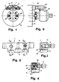
- FIG. 1 shows a front view of a machine tool spindle nose, provided with a device for positioning and blocking three mechanisms for machining with chip removal, in accordance with the invention
- FIG. 2 shows the enlarged top view of the device of FIG. 1
- FIG. 3 shows the sectional view along line A-A of FIG. 2
- FIG. 4 shows the sectional view along line C-C of FIG. 2
- FIG. 5 shows the side view of FIG. 1, with a lap multiplier installed.
- a device in accordance with the invention for positioning and blocking mechanisms, for machining with removal of shavings or trimmings, on the spindle nose of the mandrel 2 of a machine tool which is provided with means 20 for transmitting to the moving parts of the mechanisms the rotational movement of the mandrel, consists of a block 1 of irregular prismatic shape, fixed frontally on the spindle nose 2 of the machine by means of two lateral screws 3, inscribed in the perimeter of said spindle nose and the front face of which is modeled in steps with three corresponding seats , a central 9 and two lateral 10, 11, which are provided with a hole 12 whose respective axes, which are parallel to that of the mandrel, are located on the same circumference concentric with the mandrel and having a radius equal to the distance between the axes of the mechanisms, i.e. at the distance between the axis of rotation of the mandrel and the axis of the
- the central seat 9 consists of a frustoconical cavity to allow the positioning of heads with a milling angle
- the two lateral seats 10, 11 are cavities of rectangular section, the hole 12 of which is in correspondence with the stud belonging to other types of operator mechanisms.
- the hole 12 in the seat 10 is in communication with a conduit 13 internal to the block 1 itself, at the end of which is connected the threaded connector 14 of a fluid supply tube, for example cutting fluid , necessary for certain types of mechanisms such as the oil feed holder; the sealing at the outlet being ensured by an O-ring 15 cooperating with the locking means of the mechanism which also has an internal hole for the passage of the fluid through its stud.
- a fluid supply tube for example cutting fluid
- the hole 12 in the seat 11 is in communication with a conduit 16 internal to the block 1 itself and at the end of which is connected the threaded connection 17 of a supply tube with another fluid, for example from the compressed air, necessary for certain types of mechanisms such as the cone cleaner and others.
- the duct 16 is advantageously provided with a closing valve produced by means of a ball 20 which is pushed by a spring 21 against an internal O-ring 22, for automatically closing the mouth of the hole 12; said ball is raised by overcoming the force of the spring 21 under the action of the stud of the corresponding mechanism introduced into the hole 12 to allow the compressed air supply circuit to be opened; in this case also, the sealing at the outlet is ensured by an O-ring 23 which cooperates with the locking means of the mechanism which also has an internal conduit for passage of the fluid through its stud.
- a generic device 24 for example a multiplier of turns, was taken from the tool magazine by means of a mechanical arm (not shown for simplification), always in the same predetermined position relative to the corresponding seat for receiving and blocking block 1, which in this case is the seat 10, so that, when the mechanism is fitted into the hole of the mandrel, the stud 25 of the blocking means 26 of the external carcass is automatically installed in correspondence with the hole 12 of the seat 10.
Landscapes
- Engineering & Computer Science (AREA)
- Mechanical Engineering (AREA)
- Auxiliary Devices For Machine Tools (AREA)
- Jigs For Machine Tools (AREA)
Applications Claiming Priority (2)
| Application Number | Priority Date | Filing Date | Title |
|---|---|---|---|
| IT09430/88A IT1222261B (it) | 1988-06-21 | 1988-06-21 | Dispositivo per il posizionamento ed il bloccaggio univoci e automatici sul naso del mandrino di una macchina utensile e simili,di meccanismi per differenti lavorazioni meccaniche con asportazione di truciolo |
| IT943088 | 1988-06-21 |
Publications (3)
| Publication Number | Publication Date |
|---|---|
| EP0347513A2 true EP0347513A2 (de) | 1989-12-27 |
| EP0347513A3 EP0347513A3 (en) | 1990-06-13 |
| EP0347513B1 EP0347513B1 (de) | 1992-08-19 |
Family
ID=11130040
Family Applications (1)
| Application Number | Title | Priority Date | Filing Date |
|---|---|---|---|
| EP88830548A Expired - Lifetime EP0347513B1 (de) | 1988-06-21 | 1988-12-21 | Vorrichtung zum Positionieren und Blockieren auf dem Spindelkopf einer Werkzeugmaschine von verschiedenen Einrichtungen zur mechanischen Bearbeitung |
Country Status (5)
| Country | Link |
|---|---|
| US (1) | US4992012A (de) |
| EP (1) | EP0347513B1 (de) |
| JP (1) | JPH01321141A (de) |
| DE (1) | DE3873915T2 (de) |
| IT (1) | IT1222261B (de) |
Cited By (1)
| Publication number | Priority date | Publication date | Assignee | Title |
|---|---|---|---|---|
| CN104339232A (zh) * | 2014-10-22 | 2015-02-11 | 北京奥博汽车电子电器有限公司 | 一种双头钻攻加工机床 |
Families Citing this family (6)
| Publication number | Priority date | Publication date | Assignee | Title |
|---|---|---|---|---|
| DE19621240C2 (de) * | 1996-05-25 | 1998-05-28 | Chiron Werke Gmbh | Werkzeughalter mit Kühlmittelrohr |
| DE29914930U1 (de) * | 1999-08-26 | 1999-12-09 | Deckel Maho GmbH, 87459 Pfronten | Bearbeitungseinheit einer Werkzeugmaschine |
| IT1314043B1 (it) * | 1999-10-14 | 2002-12-03 | F M Elettromeccanica S R L | Testa per macchina utensile. |
| JP4809521B2 (ja) | 2000-09-19 | 2011-11-09 | マンヨーツール株式会社 | 工具ホルダ及びその冷却装置 |
| US8720312B2 (en) * | 2010-08-05 | 2014-05-13 | Baker Hughes Incorporated | Hands-free quick-change air tool configuration |
| US9375816B2 (en) * | 2012-07-11 | 2016-06-28 | Air Turbine Technology, Inc. | Auto changer spindle mounting assembly adapted to drill tap machines |
Family Cites Families (11)
| Publication number | Priority date | Publication date | Assignee | Title |
|---|---|---|---|---|
| DE2212875C3 (de) * | 1972-03-17 | 1974-09-05 | Schiess Ag, 4000 Duesseldorf-Oberkassel | Vorrichtung zum Festspannen, Lösen und Auswechseln von Werkzeugköpfen an einer Schwerwerkzeugmaschine |
| DD143054A1 (de) * | 1979-04-21 | 1980-07-30 | Klaus Schmidt | Einrichtung an winkelbohrwerkzeugen fuer werkzeugmaschinen |
| US4679970A (en) * | 1981-08-26 | 1987-07-14 | Kearney & Trecker Corporation | High speed toolholder for a machining center |
| DE3232495C2 (de) * | 1982-09-01 | 1984-11-15 | Komet Stahlhalter- Und Werkzeugfabrik Robert Breuning Gmbh, 7122 Besigheim | Vorrichtung zur Kühlmittelzufuhr zu mit Kühlmittelkanälen versehenen, rotierenden Schneidwerkzeugen für die spanende Metallbearbeitung, insbesondere Bohrwerkzeugen |
| US4624043A (en) * | 1982-09-29 | 1986-11-25 | The Boeing Company | Quick release tool holder for robots |
| JPS59171050U (ja) * | 1983-04-28 | 1984-11-15 | 株式会社 溝口鉄工所 | オイルホ−ル付ホルダ− |
| IT1198610B (it) * | 1983-05-24 | 1988-12-21 | Bakuer Italiana Spa | Dispositivo distributore di refrigerante dall'esterno del mandrino di una macchina utensile applicabile su macchine a controllo numerico e centri di lavoro |
| JPS6062434A (ja) * | 1983-09-14 | 1985-04-10 | Fuji Seikou Kk | 回転切削工具ホルダ |
| DE3515520A1 (de) * | 1985-04-30 | 1986-10-30 | O. Dörries GmbH, 5160 Düren | Vorrichtung zum halten von werkzeugen am meisselschieber einer werkzeugmaschine |
| US4709465A (en) * | 1985-10-04 | 1987-12-01 | The Ingersoll Milling Machine Company | Interchangeable spindle-head milling system |
| US4795293A (en) * | 1986-09-05 | 1989-01-03 | Mizoguchi Iron Works & Co., Ltd. | Unit for mounting a cutting tool |
-
1988
- 1988-06-21 IT IT09430/88A patent/IT1222261B/it active
- 1988-12-21 DE DE8888830548T patent/DE3873915T2/de not_active Expired - Fee Related
- 1988-12-21 EP EP88830548A patent/EP0347513B1/de not_active Expired - Lifetime
-
1989
- 1989-01-24 JP JP1014939A patent/JPH01321141A/ja active Pending
-
1990
- 1990-03-05 US US07/490,541 patent/US4992012A/en not_active Expired - Fee Related
Cited By (2)
| Publication number | Priority date | Publication date | Assignee | Title |
|---|---|---|---|---|
| CN104339232A (zh) * | 2014-10-22 | 2015-02-11 | 北京奥博汽车电子电器有限公司 | 一种双头钻攻加工机床 |
| CN104339232B (zh) * | 2014-10-22 | 2017-01-25 | 北京奥博汽车电子电器有限公司 | 一种双头钻攻加工机床 |
Also Published As
| Publication number | Publication date |
|---|---|
| IT8809430A0 (it) | 1988-06-21 |
| IT1222261B (it) | 1990-09-05 |
| DE3873915D1 (de) | 1992-09-24 |
| JPH01321141A (ja) | 1989-12-27 |
| US4992012A (en) | 1991-02-12 |
| DE3873915T2 (de) | 1993-01-14 |
| EP0347513A3 (en) | 1990-06-13 |
| EP0347513B1 (de) | 1992-08-19 |
Similar Documents
| Publication | Publication Date | Title |
|---|---|---|
| EP0068952A1 (de) | Werkzeugmaschinen mit hoher Produktivität | |
| US5064316A (en) | Ball nose milling tool | |
| FR2565139A1 (fr) | Machine-outil a deux broches porte-piece | |
| EP0347513A2 (de) | Vorrichtung zum Positionieren und Blockieren auf dem Spindelkopf einer Werkzeugmaschine von verschiedenen Einrichtungen zur mechanischen Bearbeitung | |
| EP0669185A1 (de) | Magazin zum Werkzeug- oder Werkstückwechseln bei Werkzeugmaschinen | |
| JP7423036B2 (ja) | タレット旋盤用工具ホルダ | |
| EP0446198A1 (de) | Schnellwechselmechanismus mit exzentrischer sperrvorrichtung. | |
| FR2468428A1 (fr) | Dispositif de fixation d'outil, notamment pour perceuse a main | |
| WO1999021686A1 (fr) | Dispositif de support de mandrin avec transmission angulaire | |
| EP0356389B1 (de) | Antriebsvorrichtung für eine Mehrspindelbearbeitungsmaschine | |
| JPS6165738A (ja) | 急速接続機構 | |
| AU2001289997A1 (en) | Boring head | |
| EP0245177B1 (de) | Vorrichtung zum Stützen eines Werkstückes zur Ermöglichung der Bearbeitung auf seiner fünften Fläche | |
| FR2656820A1 (fr) | Ensemble porte-outils muni d'un dispositif de palpage. | |
| EP0194227A1 (de) | Vorrichtung zur Voreinstellung des Werkzeugs von Werkzeugmaschinen | |
| EP0360947B1 (de) | Spannzange zum Halten eines Werkzeuges, insbesondere einer Schneidwerkzeuges | |
| FR2532227A1 (fr) | Dispositif d'amenee de refrigerant a des outils de coupe pour l'usinage de metaux avec copeaux, notamment des outils de percage, rotatifs munis de canaux pour refrigerant | |
| FR2703280A1 (fr) | Procédé et dispositif de montage d'outillages. | |
| JPS6018278Y2 (ja) | 工作機械の切削用流体供給装置 | |
| FR2504037A1 (fr) | Centre de tournage a commande numerique permettant des operations de fraisage | |
| EP0267117B1 (de) | Verfahren zum Spannen von Werkstücken und Vorrichtung zur Ausführung von Arbeitsgängen an diesen Stücken | |
| EP0114443B1 (de) | Werkzeug-Support für Werkzeugmaschine | |
| EP0211128B1 (de) | Werkzeugsupport einer automatischen Drehmaschine mit Kühleinrichtung für diese Werkzeuge | |
| FR2561147A1 (fr) | Outil de percage avec alimentation en agent de refroidissement | |
| EP0577564B1 (de) | Geschwindigkeitsübersetzer mit dreifacher Kühlmittelversorgung |
Legal Events
| Date | Code | Title | Description |
|---|---|---|---|
| PUAI | Public reference made under article 153(3) epc to a published international application that has entered the european phase |
Free format text: ORIGINAL CODE: 0009012 |
|
| AK | Designated contracting states |
Kind code of ref document: A2 Designated state(s): CH DE ES FR GB LI SE |
|
| PUAL | Search report despatched |
Free format text: ORIGINAL CODE: 0009013 |
|
| AK | Designated contracting states |
Kind code of ref document: A3 Designated state(s): CH DE ES FR GB LI SE |
|
| 17P | Request for examination filed |
Effective date: 19900831 |
|
| 17Q | First examination report despatched |
Effective date: 19910604 |
|
| GRAA | (expected) grant |
Free format text: ORIGINAL CODE: 0009210 |
|
| AK | Designated contracting states |
Kind code of ref document: B1 Designated state(s): CH DE ES FR GB LI SE |
|
| PG25 | Lapsed in a contracting state [announced via postgrant information from national office to epo] |
Ref country code: SE Free format text: THE PATENT HAS BEEN ANNULLED BY A DECISION OF A NATIONAL AUTHORITY Effective date: 19920819 Ref country code: ES Free format text: THE PATENT HAS BEEN ANNULLED BY A DECISION OF A NATIONAL AUTHORITY Effective date: 19920819 |
|
| GBT | Gb: translation of ep patent filed (gb section 77(6)(a)/1977) | ||
| REF | Corresponds to: |
Ref document number: 3873915 Country of ref document: DE Date of ref document: 19920924 |
|
| PG25 | Lapsed in a contracting state [announced via postgrant information from national office to epo] |
Ref country code: LI Effective date: 19921231 Ref country code: CH Effective date: 19921231 |
|
| PLBE | No opposition filed within time limit |
Free format text: ORIGINAL CODE: 0009261 |
|
| STAA | Information on the status of an ep patent application or granted ep patent |
Free format text: STATUS: NO OPPOSITION FILED WITHIN TIME LIMIT |
|
| 26N | No opposition filed | ||
| REG | Reference to a national code |
Ref country code: CH Ref legal event code: PL |
|
| PGFP | Annual fee paid to national office [announced via postgrant information from national office to epo] |
Ref country code: FR Payment date: 19951130 Year of fee payment: 8 |
|
| PGFP | Annual fee paid to national office [announced via postgrant information from national office to epo] |
Ref country code: GB Payment date: 19951208 Year of fee payment: 8 |
|
| PGFP | Annual fee paid to national office [announced via postgrant information from national office to epo] |
Ref country code: DE Payment date: 19960229 Year of fee payment: 8 |
|
| REG | Reference to a national code |
Ref country code: FR Ref legal event code: CD Ref country code: FR Ref legal event code: CA |
|
| PG25 | Lapsed in a contracting state [announced via postgrant information from national office to epo] |
Ref country code: GB Effective date: 19961221 |
|
| GBPC | Gb: european patent ceased through non-payment of renewal fee |
Effective date: 19961221 |
|
| PG25 | Lapsed in a contracting state [announced via postgrant information from national office to epo] |
Ref country code: FR Effective date: 19970829 |
|
| PG25 | Lapsed in a contracting state [announced via postgrant information from national office to epo] |
Ref country code: DE Effective date: 19970902 |
|
| REG | Reference to a national code |
Ref country code: FR Ref legal event code: ST |