EP0347487B1 - Pomace-submerging device - Google Patents
Pomace-submerging device Download PDFInfo
- Publication number
- EP0347487B1 EP0347487B1 EP88110121A EP88110121A EP0347487B1 EP 0347487 B1 EP0347487 B1 EP 0347487B1 EP 88110121 A EP88110121 A EP 88110121A EP 88110121 A EP88110121 A EP 88110121A EP 0347487 B1 EP0347487 B1 EP 0347487B1
- Authority
- EP
- European Patent Office
- Prior art keywords
- vat
- support
- pressing
- rod
- moved
- Prior art date
- Legal status (The legal status is an assumption and is not a legal conclusion. Google has not performed a legal analysis and makes no representation as to the accuracy of the status listed.)
- Expired - Lifetime
Links
Images
Classifications
-
- C—CHEMISTRY; METALLURGY
- C12—BIOCHEMISTRY; BEER; SPIRITS; WINE; VINEGAR; MICROBIOLOGY; ENZYMOLOGY; MUTATION OR GENETIC ENGINEERING
- C12G—WINE; PREPARATION THEREOF; ALCOHOLIC BEVERAGES; PREPARATION OF ALCOHOLIC BEVERAGES NOT PROVIDED FOR IN SUBCLASSES C12C OR C12H
- C12G1/00—Preparation of wine or sparkling wine
- C12G1/02—Preparation of must from grapes; Must treatment and fermentation
- C12G1/0216—Preparation of must from grapes; Must treatment and fermentation with recirculation of the must for pomage extraction
Definitions
- the invention relates to the wine industry, and more particularly the operation of "crushing” or “pegging” of the marc hat during a vinification in red.
- the punching device comprises a punching tool attached to the end of a rod, with means controlled to ensure the displacement of this rod in three dimensions, these means being carried by a support. capable of being immobilized with respect to a tank to perform the punching down operation thereon, then to be released and moved from this tank to another tank.
- the punching-down tool can advantageously be conical or biconical, and said rod is preferably the rod of a pigging cylinder ensuring the back-and-forth movements in the axial direction to make the pigging tool penetrate into the marc cap. and extract it.
- the picking tool 1 can be a lenticular disc, the two faces of which are conical and convex, symmetrical or not, the cones ensuring good penetration into the marc cap on the descent and on the ascent. It can also, as in the examples shown, be constituted by a simple cone, convex on its upper face and concave on its lower face, the latter ensuring a suction effect of the juice during the ascent of the tool. Naturally, other forms could also be envisaged.
- This picking cylinder 4 therefore ensures the main movement of delivery towards the inside of the tank 6 of the marc cap 5, and it must be combined with two other movements to allow operating at various points on the horizontal surface of the cap 5.
- the apparatus comprises a support 7, in the form of a double cross gantry; capable of being removably attached to the tank 6, this support comprising an arm 8, movable in rotation, by means of a suitable geared motor 10, around a vertical axis 9 coaxial with the tank 6.
- a end of the arm 8 carries the body of the picking cylinder 4 by means of an articulation axis 11 perpendicular to the plane of the axis 9 and of the arm 8, so that the cylinder 4 and its rod 3 can move in a vertical radial plane passing through the axis 9.
- the tilting movements of this jack 4 in this plane around the articulation 11 are controlled by a radial control jack 12, articulated at 13 on the body 4 of the picking jack and at 14 on the end of the arm 8 opposite the joint 11.
- the gantry 7 is removably attached to the tank 6 by means of pins 15 passing through yokes 16 located at the lower end of each of the four uprights 17 of the gantry 7, and fixing lugs 18 welded to the top of the tank.
- the gantry 7 also has at its upper end sling ears 19 allowing, after release of the gantry by removing the pins 15, to move it from one tank to another using a conventional lifting device not shown.
- the four uprights 17 are preferably braced by horizontal bars 20, straight or curved, serving both as spacers and guardrails.
- the pegging cylinder 4 can advantageously be retracted and raised in the position shown in broken lines in FIG. 1, in order to release it from the marc cap. This position also facilitates the transfer from one tank to another.
- the support 7a is in the form of a bracket, with a single upright 17a and an arm 8a in cantilever, this arm 8a always being movable in rotation about a vertical axis 9a , which in this case is not coaxial with the tank as in the previous case, but in the lateral position.
- the upright 17a of the support 7a is preferably carried by a carriage 23 which can roll on the ground, on rails, or on a raised walkway traversing for example an alignment of tanks.
- a braking or blocking means not shown, makes it possible to immobilize the carriage 23 and the support 17a opposite each tank 6 and to release it.
- the upright 17a of the support can advantageously be itself telescopic in the vertical direction and actuated by an auxiliary cylinder 24 which is operated in extension during the transfer or the resting of the device. This latter arrangement also makes it possible to quickly adapt the device to various heights of tanks if necessary.
- the jacks and the geared motors are supplied by a hydraulic unit and an electrical control box which can be actuated manually by an observer more or less distant from the tank. But they can also be controlled by an automatic programmer from pre-recorded data ensuring not only the complete kinematics of the various movements, but also the adjustment of the amplitude, the frequency and the duration of the various operations, with a view to periodic operation. automatic without supervision.
Landscapes
- Chemical & Material Sciences (AREA)
- Organic Chemistry (AREA)
- Engineering & Computer Science (AREA)
- Biochemistry (AREA)
- Bioinformatics & Cheminformatics (AREA)
- General Engineering & Computer Science (AREA)
- General Health & Medical Sciences (AREA)
- Genetics & Genomics (AREA)
- Life Sciences & Earth Sciences (AREA)
- Wood Science & Technology (AREA)
- Zoology (AREA)
- Health & Medical Sciences (AREA)
- Apparatus Associated With Microorganisms And Enzymes (AREA)
- Food-Manufacturing Devices (AREA)
- Surgical Instruments (AREA)
- Percussion Or Vibration Massage (AREA)
- Rehabilitation Tools (AREA)
- Massaging Devices (AREA)
- Finger-Pressure Massage (AREA)
- Processing Of Meat And Fish (AREA)
- Instruments For Viewing The Inside Of Hollow Bodies (AREA)
- Electrical Discharge Machining, Electrochemical Machining, And Combined Machining (AREA)
- Structures Of Non-Positive Displacement Pumps (AREA)
- Removal Of Floating Material (AREA)
- Refuse Collection And Transfer (AREA)
Abstract
Description
L'invention concerne l'industrie vinicole, et plus particulièrement l'opération de "foulage" ou "pigeage" du chapeau de marc au cours d'une vinification en rouge.The invention relates to the wine industry, and more particularly the operation of "crushing" or "pegging" of the marc hat during a vinification in red.
Le vin est une boisson résultant de la fermentation du raisin frais. Le vin rouge est obtenu par fermentation du moût de raisins rouges avec leurs peaux, leurs pépins et, le cas échéant, tout ou partie de la rafle qui est l'armature ligneuse de la grappe. La fermentation provoque la transformation du sucre du raisin en alcool éthylique, en gaz carbonique et en produits secondaires, ceci sous l'action des levures. Les sucres fermentescibles et l'eau se trouvent essentiellement dans la pulpe du raisin tandis que les produits qui donnent naissance à la couleur et aux arômes se localisent dans la peau des grains. Au cours de la cuvaison, le gaz carbonique qui se dégage du moût en fermentation soulève les parties solides et les entraîne en surface sous forme de "chapeau".Wine is a drink resulting from the fermentation of fresh grapes. Red wine is obtained by fermentation of the must of red grapes with their skins, their seeds and, if necessary, all or part of the cob which is the woody backbone of the bunch. Fermentation causes the transformation of grape sugar into ethyl alcohol, carbon dioxide and secondary products, under the action of yeasts. Fermentable sugars and water are mainly found in the grape pulp while the products that give rise to color and aromas are located in the skin of the beans. During fermentation, the carbon dioxide released from the fermenting must raises the solid parts and carries them to the surface in the form of a "cap".
Cette séparation des phases solides et liquide du moût a pour inconvénients principaux : une hétérogénéité de températures de fermentation, une aération excessive du chapeau risquant de développer de mauvais ferments, et surtout une mauvaise dilution des principes aromatiques et colorants.This separation of the solid and liquid phases of the must has the main drawbacks: heterogeneity of fermentation temperatures, excessive aeration of the cap which risks developing bad ferments, and above all a poor dilution of the principles. aromatic and coloring.
Pour éviter ces défauts, on utilise habituellement les procédés suivants :
- Foulage aux pieds ou à la pige : ce procédé, le plus ancien, consiste à refouler aux pieds le chapeau dans le moût. Il est peu employé en raison du danger que présente pour les opérateurs le dégagement de gaz carbonique. Il a été remplacé par le foulage au moyen d'une perche munie d'un disque ou d'une crosse enfoncée manuellement dans le chapeau. La manoeuvre de ces perches dites "piges" ou "pigeous" est difficile, pénible et le foulage ou "pigeage" est souvent incomplet.
- Immersion du chapeau : l'immersion du chapeau dans le moût peut être réalisée, soit en permanence pendant toute la fermentation au moyen de claies, grilles ou similaires, soit de temps en temps par action de pistons ou de râteaux intégrés dans la cuve, soit par mouvements imprimés à la cuve elle-même, tels que la mise en rotation ou le basculement de cuves horizontales.
- Pressing on the feet or freelancing: this process, the oldest, consists of pushing the hat back into the must. It is little used because of the danger for operators from the release of carbon dioxide. It was replaced by fulling by means of a pole fitted with a disc or a stick inserted manually into the hat. The operation of these so-called "rods" or "pigeous" is difficult, painful and fulling or "pigeage" is often incomplete.
- Immersion of the cap: the immersion of the cap in the must can be carried out, either permanently during the whole fermentation by means of racks, grids or the like, or from time to time by the action of pistons or rakes integrated in the tank, or by movements printed on the tank itself, such as the rotation or tilting of horizontal tanks.
Ces procédés présentent les inconvénients d'intégrer à l'intérieur des cuves des dispositifs spécifiques fixes, onéreux et difficiles à nettoyer, d'effectuer une action sur le chapeau sans possibilité de contrôle visuel, ou encore de nécessiter une forme particulière de cuves les rendant difficilement utilisables pour une autre fonction que la fermentation proprement dite.These methods have the drawbacks of integrating specific fixed, expensive and difficult-to-clean devices inside the tanks, of performing an action on the cap without the possibility of visual control, or of requiring a particular form of tanks making them difficult to use for a function other than actual fermentation.
Le but de l'invention est d'éliminer les inconvénients précédents en permettant un pigeage du chapeau marc depuis l'extérieur d'une cuve de façon complète, contrôlable et régulable au moyen d'un appareil non intégré à la cuve.The object of the invention is to eliminate the above drawbacks by allowing the cap cap to be punched down from the outside of a tank in a complete, controllable and adjustable manner by means of a device not integrated into the tank.
Pour cela, l'appareil de pigeage selon l'invention comporte un outil de pigeage fixé à l'extrémité d'une tige, avec des moyens commandés pour assurer le déplacement de cette tige dans les trois dimensions, ces moyens étant portés par un support susceptible d'être immobilisé par rapport à une cuve pour effectuer sur celle-ci l'opération de pigeage, puis d'être libéré et déplacé de cette cuve à une autre cuve.For this, the punching device according to the invention comprises a punching tool attached to the end of a rod, with means controlled to ensure the displacement of this rod in three dimensions, these means being carried by a support. capable of being immobilized with respect to a tank to perform the punching down operation thereon, then to be released and moved from this tank to another tank.
L'outil de pigeage peut avantageusement être conique ou biconique, et ladite tige est de préférence la tige d'un vérin pigeur assurant les mouvements de va-et-vient dans le sens axial pour faire pénétrer l'outil pigeur dans le chapeau de marc et l'en extraire.The punching-down tool can advantageously be conical or biconical, and said rod is preferably the rod of a pigging cylinder ensuring the back-and-forth movements in the axial direction to make the pigging tool penetrate into the marc cap. and extract it.
Ledit support porte de préférence un bras, mobile en rotation autour d'un axe vertical, ce bras portant à son tour le vérin pigeur d'une manière mobile en rotation ou en translation dans un plan vertical radial.Said support preferably carries an arm, movable in rotation about a vertical axis, this arm in turn carrying the pickup cylinder in a manner movable in rotation or in translation in a vertical radial plane.
D'autres particularités de l'invention apparaîtront dans la description qui va suivre de deux modes de réalisation pris comme exemples et représentés sur le dessin annexé, sur lequel :
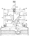
- la figure 1 est une vue en élévation et en coupe partielle d'un premier mode de réalisation; et
- la figure 2 est une vue similaire d'un deuxième mode de réalisation.
- Figure 1 is an elevational view in partial section of a first embodiment; and
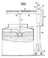
- Figure 2 is a similar view of a second embodiment.
L'outil pigeur 1 peut être un disque lenticulaire dont les deux faces sont coniques et convexes, symétriques ou non, les cônes assurant une bonne pénétration dans le chapeau de marc à la descente et à la remontée. Il peut également, comme dans les exemples représentés, être constitué par un simple cône, convexe sur sa face supérieure et concave sur sa face inférieure, cette dernière assurant un effet de succion du jus lors de la remontée de l'outil. Naturellement, d'autres formes pourraient également être envisagées.The
Cet outil pigeur 1 est monté, de préférence par un raccordement démontable 2, à une tige 3, qui peut avantageusement être la tige d'un vérin pigeur 4 permettant d'assurer les mouvements de va-et-vient dans le sens axial de la tige 3 et de l'outil 1, afin de faire pénétrer l'outil pigeur dans le chapeau de marc 5 et de l'en extraire.This
Ce vérin pigeur 4 assure donc le mouvement principal de refoulement vers l'intérieur de la cuve 6 du chapeau de marc 5, et il doit être combiné avec deux autres mouvements pour permettre d'opérer en divers points de la surface horizontale du chapeau 5.This picking
Pour cela, dans le premier mode de réalisation de la figure 1, l'appareil comporte un support 7, en forme de portique double en croix; susceptible d'être fixé de manière amovible sur la cuve 6, ce support comportant un bras 8, mobile en rotation, grâce à un moto-réducteur approprié 10, autour d'un axe vertical 9 coaxial à la cuve 6. En outre, une extrémité du bras 8 porte le corps du vérin pigeur 4 par l'intermédiaire d'un axe d'articulation 11 perpendiculaire au plan de l'axe 9 et du bras 8, de manière que le vérin 4 ainsi que sa tige 3 puissent se déplacer dans un plan vertical radial passant par l'axe 9. Les mouvements de basculement de ce vérin 4 dans ce plan autour de l'articulation 11 sont commandés par un vérin de commande radiale 12, articulé en 13 sur le corps 4 du vérin pigeur et en 14 sur l'extrémité du bras 8 opposée à l'articulation 11.For this, in the first embodiment of Figure 1, the apparatus comprises a support 7, in the form of a double cross gantry; capable of being removably attached to the
La combinaison de ce mouvement de basculement dans le plan radial et de rotation de ce plan radial autour de l'axe 9 permet donc effectivement d'atteindre tous les points du chapeau 5 afin d'y faire plonger l'outil pigeur 1.The combination of this tilting movement in the radial plane and of rotation of this radial plane around the axis 9 therefore effectively makes it possible to reach all the points of the
Dans le mode de réalisation particulier de la figure 1, le portique 7 est fixé de manière amovible sur la cuve 6 au moyen de broches 15 traversant des chapes 16 situées à l'extrémité inférieure de chacun des quatre montants 17 du portique 7, et des oreilles de fixation 18 soudées sur le dessus de la cuve. D'autre part, le portique 7 comporte également à son extrémité supérieure des oreilles d'élinguage 19 permettant, après libération du portique par retrait des broches 15, de déplacer celui-ci d'une cuve à une autre à l'aide d'un engin de levage conventionnel non représenté.In the particular embodiment of Figure 1, the gantry 7 is removably attached to the
Par ailleurs, les quatre montants 17 sont de préférence entretoisés par des barres horizontales 20, droites ou courbes, servant à la fois d'entretoises et de rambardes.Furthermore, the four
Lorsque le pigeage n'est pas en cours, le vérin de pigeage 4 peut avantageusement être rétracté et relevé dans la position représentée en traits interrompus sur la figure 1, afin de le dégager du chapeau de marc. Cette position facilite en outre le transfert d'une cuve à une autre.When the pegging is not in progress, the pegging
Dans le mode de réalisation de la figure 2, le support 7a est en forme de potence, avec un montant unique 17a et un bras 8a en porte-à-faux, ce bras 8a étant toujours mobile en rotation autour d'un axe vertical 9a, lequel dans ce cas n'est pas coaxial à la cuve comme dans le cas précédent, mais en position latérale.In the embodiment of FIG. 2, the
Le vérin pigeur 4 se déplace dans un plan vertical radial passant par cet axe 9a, mais dans ce cas, ce déplacement est un déplacement en translation le long du bras 8a. Pour cela, on utilise, dans l'exemple représenté, à la place du vérin de déplacement radial 12 précédent, une vis 21, entraînée par un moteur approprié, et entraînant un chariot 22 qui coulisse le long du bras 8a et qui porte rigidement la base du corps 4 du vérin pigeur.The picking
Pour faciliter le mouvement de l'appareil d'une cuve à une autre, le montant 17a du support 7a est de préférence porté par un chariot 23 pouvant rouler sur le sol, sur des rails, ou sur une passerelle surélevée parcourant par exemple un alignement de cuves. Un moyen de freinage ou de blocage non représenté permet d'immobiliser le chariot 23 et le support 17a en regard de chaque cuve 6 et de l'en libérer.To facilitate the movement of the apparatus from one tank to another, the upright 17a of the
En outre, pour faciliter le dégagement de l'outil lors du transfert de cuve à cuve, tout en évitant une course exagérée pour le vérin pigeur 4, le montant 17a du support peut avantageusement être lui-même télescopique dans le sens vertical et actionné par un vérin auxiliaire 24 qui est manoeuvré en extension lors du transfert ou de la mise au repos de l'appareil. Cette dernière disposition permet en outre d'adapter très rapidement l'appareil à diverses hauteurs de cuves si nécessaire.In addition, to facilitate the release of the tool during the transfer from tank to tank, while avoiding an exaggerated stroke for the picking
Dans les deux modes de réalisation, les vérins et les moto-réducteurs sont alimentés par une centrale hydraulique et un coffret électrique de commande qui peuvent être actionnés manuellement par un observateur plus ou moins éloigné de la cuve. Mais ils peuvent également être commandés par un programmateur automatique à partir de données préenregistrées assurant non seulement la cinématique complète des divers mouvements, mais également le réglage de l'amplitude, la fréquence et la durée des diverses opérations, en vue d'un fonctionnement périodique automatique sans surveillance.In both embodiments, the jacks and the geared motors are supplied by a hydraulic unit and an electrical control box which can be actuated manually by an observer more or less distant from the tank. But they can also be controlled by an automatic programmer from pre-recorded data ensuring not only the complete kinematics of the various movements, but also the adjustment of the amplitude, the frequency and the duration of the various operations, with a view to periodic operation. automatic without supervision.
Claims (8)
- Apparatus for pressing the marc head (5) inside a succession of vinification vats (6), characterised in that it comprises a pressing tool (1) attached to the end of a rod (3) with controlled means (4, 10, 12; 4, 24, 10, 21) for ensuring the three-dimensional movement of this rod, these means being carried by a support (7, 7a) capable of being immobilised relative to a vat (6) in order to carry out the pressing operation in this vat and then released and moved from this vat to another vat.
- Apparatus according to claim 1, characterised in that at least the upper surface of the pressing tool (1) is conical and convex, while its lower surface can be conical and convex or concave.
- Pressing apparatus according to one of the preceding claims, characterised in that the said rod is the rod (3) of a pressing jack (4) ensuring to-and-fro movements in the axial direction for causing the pressing tool (1) to enter the marc head (5) and to remove it therefrom.
- Apparatus according to one of the preceding claims, characterised in that the said support (7, 7a) carries an arm (8, 8a) which can be moved for rotation around a vertical axis (9, 9a), this arm in turn carrying the pressing jack (4) in such a way that it can be moved for rotation or translational motion in a radial, vertical plane.
- Apparatus according to claim 4, characterised in that the vertical axis (9) is coaxial with the vat, and in that the said support (7) is in the form of a gantry resting on the periphery of the vat.
- Apparatus according to claim 4, characterised in that the said vertical axis (9a) is in a lateral position relative to the vat and in that the support (7a) is in the form of a bracket.
- Apparatus according to one of the preceding claims, characterised in that the said support (7) is arranged so that it can be attached in an easily removable manner to each vat (6), and so that it can be transported after release by a hoist.
- Apparatus according to one of claims 1 to 6, characterised in that the support (7a) is carried by a carriage (23) moving along on the ground, on rails or on a bridge so that it can pass from the region of one vat to another, this carriage comprising means for braking or locking in its working positions.
Applications Claiming Priority (1)
| Application Number | Priority Date | Filing Date | Title |
|---|---|---|---|
| FR8705946A FR2614314B1 (en) | 1987-04-27 | 1987-04-27 | PIGEAGE APPARATUS. |
Publications (2)
| Publication Number | Publication Date |
|---|---|
| EP0347487A1 EP0347487A1 (en) | 1989-12-27 |
| EP0347487B1 true EP0347487B1 (en) | 1993-01-07 |
Family
ID=9350524
Family Applications (1)
| Application Number | Title | Priority Date | Filing Date |
|---|---|---|---|
| EP88110121A Expired - Lifetime EP0347487B1 (en) | 1987-04-27 | 1988-06-24 | Pomace-submerging device |
Country Status (6)
| Country | Link |
|---|---|
| EP (1) | EP0347487B1 (en) |
| AT (1) | ATE84310T1 (en) |
| DE (1) | DE3877354T2 (en) |
| ES (1) | ES2038245T3 (en) |
| FR (1) | FR2614314B1 (en) |
| GR (1) | GR3007438T3 (en) |
Families Citing this family (10)
| Publication number | Priority date | Publication date | Assignee | Title |
|---|---|---|---|---|
| EP0916723B1 (en) * | 1997-11-17 | 2001-10-17 | Tec Inox | Pomace-submerging apparatus for vinification |
| FR2778411B1 (en) * | 1998-05-07 | 2002-04-12 | Seguin Moreau Et Cie | PIGEAGE ASSISTANCE DEVICE AND PIGEAGE METHOD |
| FR2794769A1 (en) * | 1999-06-14 | 2000-12-15 | Denis Clavel | Gentle mixing of grapes and juice during wine making by submerging the grapes, by lowering vanes from above |
| EP2060624B1 (en) * | 2007-11-13 | 2012-01-04 | L.A.S.I. s.r.l. | Cap breaking apparatus for any pressed vegetal product |
| IT1393941B1 (en) * | 2009-04-10 | 2012-05-17 | Dogliotti Srl | WINE-MAKING EQUIPMENT |
| FR2952647B1 (en) * | 2009-11-17 | 2013-02-15 | Peyssard Fils | MOBILE DEVICE FOR PIGING A WINE TANK |
| FR2979916B1 (en) * | 2011-09-09 | 2014-08-29 | Serap Industries | PILING DEVICE |
| EP3164480B1 (en) * | 2014-07-04 | 2018-05-02 | Parsec S.r.l. | Improved pneumatic punching down device for wine-making |
| IT201800002911A1 (en) * | 2018-02-21 | 2019-08-21 | NoForm Srl | Equipment for the fulling treatment of a vegetable product in the form of crushed grapes |
| FR3127499A1 (en) | 2021-09-29 | 2023-03-31 | Julien MIAILHE | Automatic puncher |
Family Cites Families (4)
| Publication number | Priority date | Publication date | Assignee | Title |
|---|---|---|---|---|
| FR1316517A (en) * | 1961-10-31 | 1963-02-01 | Improvements to mechanical agitators | |
| US3179264A (en) * | 1963-05-27 | 1965-04-20 | Ederer Corp | Rake crane |
| US3308994A (en) * | 1965-04-07 | 1967-03-14 | Baker Perkins Inc | Feeder apparatus |
| CH548927A (en) * | 1971-02-26 | 1974-05-15 | Buchs Metallwerk Ag | PLANT FOR STORAGE AND TREATMENT OF WINE OR FRUIT JUICE IN TANKS. |
-
1987
- 1987-04-27 FR FR8705946A patent/FR2614314B1/en not_active Expired - Lifetime
-
1988
- 1988-06-24 EP EP88110121A patent/EP0347487B1/en not_active Expired - Lifetime
- 1988-06-24 ES ES198888110121T patent/ES2038245T3/en not_active Expired - Lifetime
- 1988-06-24 DE DE8888110121T patent/DE3877354T2/en not_active Expired - Fee Related
- 1988-06-24 AT AT88110121T patent/ATE84310T1/en not_active IP Right Cessation
-
1993
- 1993-03-23 GR GR930400625T patent/GR3007438T3/el unknown
Also Published As
| Publication number | Publication date |
|---|---|
| GR3007438T3 (en) | 1993-07-30 |
| DE3877354T2 (en) | 1993-08-05 |
| FR2614314A1 (en) | 1988-10-28 |
| EP0347487A1 (en) | 1989-12-27 |
| FR2614314B1 (en) | 1990-05-11 |
| ATE84310T1 (en) | 1993-01-15 |
| ES2038245T3 (en) | 1993-07-16 |
| DE3877354D1 (en) | 1993-02-18 |
Similar Documents
| Publication | Publication Date | Title |
|---|---|---|
| EP0347487B1 (en) | Pomace-submerging device | |
| EP0916723B1 (en) | Pomace-submerging apparatus for vinification | |
| CA1305960C (en) | Mexer-agitator, especially for microwave ovens | |
| FR2952647A1 (en) | Movable device for pressing a grape wine tank containing mast composed of juice and marc, comprises a frame, a counterweight unit, a rolling unit, and a pressing unit, where the marc has a tendency to form a cap layer on the juice | |
| EP0824064A1 (en) | Pressing apparatus with a vertical axis of movement | |
| US4428680A (en) | Method and apparatus for mixing liquid and paste-like substances | |
| EP1554370B1 (en) | Grape treatment method for wine production and winemaking container | |
| US20210108164A1 (en) | Punch down apparatus | |
| EP0546910B1 (en) | Grain steeping vessel | |
| FR2778411A1 (en) | Reciprocating tool for breaking up floating header layer of grape skins formed during production of red wine | |
| EP0673997A1 (en) | Process and apparatus for the brewing of beer | |
| FR2596410A2 (en) | Improvements made to methods and devices for vinification | |
| JPH01135455A (en) | Buffing-polisher for inner surface of tank | |
| FR2979916A1 (en) | Device, useful to crumb and drive cap of marc formed above juice contained in winemaking tank, comprises punching member disposed at free end of rod of first cylinder, and second cylinder, where cylinders is mounted on frame and chassis | |
| FR3127499A1 (en) | Automatic puncher | |
| CN216584934U (en) | Separation juice extractor for brewing fruit wine | |
| CN218615563U (en) | Small-tonnage hydraulic garbage squeezing equipment | |
| CN115414989B (en) | Device is thinned with flowers and plants raw and other materials to spices | |
| CN215905779U (en) | A hoisting device for production of coconut can | |
| CN214262029U (en) | Grape triturating device for wine preparation | |
| CN220916488U (en) | Fruit thinning pesticide residue removing device | |
| FR2775429A1 (en) | Automatic cutter for vegetables such as squashes and pumpkins | |
| CN216674608U (en) | Electric vegetable pressing device for making pickled vegetable | |
| FR2591420A1 (en) | Silo-emptying machine with a claw | |
| FR2819823A1 (en) | DEVICE FOR THE PRODUCTION OF RED WINE |
Legal Events
| Date | Code | Title | Description |
|---|---|---|---|
| PUAI | Public reference made under article 153(3) epc to a published international application that has entered the european phase |
Free format text: ORIGINAL CODE: 0009012 |
|
| AK | Designated contracting states |
Kind code of ref document: A1 Designated state(s): AT BE CH DE ES FR GB GR IT LI LU NL SE |
|
| 17P | Request for examination filed |
Effective date: 19900130 |
|
| 17Q | First examination report despatched |
Effective date: 19920326 |
|
| GRAA | (expected) grant |
Free format text: ORIGINAL CODE: 0009210 |
|
| AK | Designated contracting states |
Kind code of ref document: B1 Designated state(s): AT BE CH DE ES FR GB GR IT LI LU NL SE |
|
| PG25 | Lapsed in a contracting state [announced via postgrant information from national office to epo] |
Ref country code: SE Effective date: 19930107 Ref country code: NL Effective date: 19930107 Ref country code: GB Effective date: 19930107 |
|
| REF | Corresponds to: |
Ref document number: 84310 Country of ref document: AT Date of ref document: 19930115 Kind code of ref document: T |
|
| REF | Corresponds to: |
Ref document number: 3877354 Country of ref document: DE Date of ref document: 19930218 |
|
| ITF | It: translation for a ep patent filed |
Owner name: MODIANO & ASSOCIATI S.R.L. |
|
| NLV1 | Nl: lapsed or annulled due to failure to fulfill the requirements of art. 29p and 29m of the patents act | ||
| REG | Reference to a national code |
Ref country code: GR Ref legal event code: FG4A Free format text: 3007438 |
|
| GBV | Gb: ep patent (uk) treated as always having been void in accordance with gb section 77(7)/1977 [no translation filed] |
Effective date: 19930107 |
|
| REG | Reference to a national code |
Ref country code: ES Ref legal event code: FG2A Ref document number: 2038245 Country of ref document: ES Kind code of ref document: T3 |
|
| PLBE | No opposition filed within time limit |
Free format text: ORIGINAL CODE: 0009261 |
|
| STAA | Information on the status of an ep patent application or granted ep patent |
Free format text: STATUS: NO OPPOSITION FILED WITHIN TIME LIMIT |
|
| 26N | No opposition filed | ||
| EPTA | Lu: last paid annual fee | ||
| PGFP | Annual fee paid to national office [announced via postgrant information from national office to epo] |
Ref country code: AT Payment date: 19950526 Year of fee payment: 8 |
|
| PGFP | Annual fee paid to national office [announced via postgrant information from national office to epo] |
Ref country code: FR Payment date: 19950614 Year of fee payment: 8 |
|
| PGFP | Annual fee paid to national office [announced via postgrant information from national office to epo] |
Ref country code: DE Payment date: 19950624 Year of fee payment: 8 |
|
| PGFP | Annual fee paid to national office [announced via postgrant information from national office to epo] |
Ref country code: LU Payment date: 19950701 Year of fee payment: 8 |
|
| PGFP | Annual fee paid to national office [announced via postgrant information from national office to epo] |
Ref country code: BE Payment date: 19950712 Year of fee payment: 8 |
|
| PG25 | Lapsed in a contracting state [announced via postgrant information from national office to epo] |
Ref country code: LU Free format text: LAPSE BECAUSE OF NON-PAYMENT OF DUE FEES Effective date: 19960624 Ref country code: AT Effective date: 19960624 |
|
| PG25 | Lapsed in a contracting state [announced via postgrant information from national office to epo] |
Ref country code: BE Effective date: 19960630 |
|
| BERE | Be: lapsed |
Owner name: CAVE DES VIGNERONS DE BUXY SOC. COOPERATIVE AGRIC Effective date: 19960630 Owner name: SOC. NOUVELLE DES CONSTRUCTIONS SOUDEES DU COTEAU Effective date: 19960630 |
|
| PG25 | Lapsed in a contracting state [announced via postgrant information from national office to epo] |
Ref country code: FR Effective date: 19970228 |
|
| PG25 | Lapsed in a contracting state [announced via postgrant information from national office to epo] |
Ref country code: DE Effective date: 19970301 |
|
| REG | Reference to a national code |
Ref country code: FR Ref legal event code: ST |
|
| REG | Reference to a national code |
Ref country code: FR Ref legal event code: CL |
|
| PGFP | Annual fee paid to national office [announced via postgrant information from national office to epo] |
Ref country code: GR Payment date: 20030529 Year of fee payment: 16 |
|
| PGFP | Annual fee paid to national office [announced via postgrant information from national office to epo] |
Ref country code: CH Payment date: 20030616 Year of fee payment: 16 |
|
| PG25 | Lapsed in a contracting state [announced via postgrant information from national office to epo] |
Ref country code: LI Free format text: LAPSE BECAUSE OF NON-PAYMENT OF DUE FEES Effective date: 20040630 Ref country code: CH Free format text: LAPSE BECAUSE OF NON-PAYMENT OF DUE FEES Effective date: 20040630 |
|
| PG25 | Lapsed in a contracting state [announced via postgrant information from national office to epo] |
Ref country code: GR Free format text: LAPSE BECAUSE OF NON-PAYMENT OF DUE FEES Effective date: 20050105 |
|
| REG | Reference to a national code |
Ref country code: CH Ref legal event code: PL |
|
| PG25 | Lapsed in a contracting state [announced via postgrant information from national office to epo] |
Ref country code: IT Free format text: LAPSE BECAUSE OF NON-PAYMENT OF DUE FEES;WARNING: LAPSES OF ITALIAN PATENTS WITH EFFECTIVE DATE BEFORE 2007 MAY HAVE OCCURRED AT ANY TIME BEFORE 2007. THE CORRECT EFFECTIVE DATE MAY BE DIFFERENT FROM THE ONE RECORDED. Effective date: 20050624 |
|
| PGFP | Annual fee paid to national office [announced via postgrant information from national office to epo] |
Ref country code: ES Payment date: 20070615 Year of fee payment: 20 |
|
| REG | Reference to a national code |
Ref country code: ES Ref legal event code: FD2A Effective date: 20080625 |
|
| PG25 | Lapsed in a contracting state [announced via postgrant information from national office to epo] |
Ref country code: ES Free format text: LAPSE BECAUSE OF EXPIRATION OF PROTECTION Effective date: 20080625 |