EP0346778A2 - Procédé pour éliminer des résidus - Google Patents
Procédé pour éliminer des résidus Download PDFInfo
- Publication number
- EP0346778A2 EP0346778A2 EP89110508A EP89110508A EP0346778A2 EP 0346778 A2 EP0346778 A2 EP 0346778A2 EP 89110508 A EP89110508 A EP 89110508A EP 89110508 A EP89110508 A EP 89110508A EP 0346778 A2 EP0346778 A2 EP 0346778A2
- Authority
- EP
- European Patent Office
- Prior art keywords
- mixing
- rubber
- extractant
- hydrogenated nitrile
- kneading
- Prior art date
- Legal status (The legal status is an assumption and is not a legal conclusion. Google has not performed a legal analysis and makes no representation as to the accuracy of the status listed.)
- Granted
Links
Images


Classifications
-
- C—CHEMISTRY; METALLURGY
- C08—ORGANIC MACROMOLECULAR COMPOUNDS; THEIR PREPARATION OR CHEMICAL WORKING-UP; COMPOSITIONS BASED THEREON
- C08C—TREATMENT OR CHEMICAL MODIFICATION OF RUBBERS
- C08C2/00—Treatment of rubber solutions
- C08C2/02—Purification
-
- C—CHEMISTRY; METALLURGY
- C08—ORGANIC MACROMOLECULAR COMPOUNDS; THEIR PREPARATION OR CHEMICAL WORKING-UP; COMPOSITIONS BASED THEREON
- C08C—TREATMENT OR CHEMICAL MODIFICATION OF RUBBERS
- C08C19/00—Chemical modification of rubber
- C08C19/02—Hydrogenation
Definitions
- This invention relates to a process to extract residue from hydrogenated nitrile rubber (HNBR).
- HNBR hydrogenated nitrile rubber
- the process technology as generally described herein may be suitable for the extraction of a wide variety of residues (for example, residual solvent, residual monomer, residual catalyst) from a wide variety of rubbers (such as butyl rubber and its halogenated derivatives, acrylonitrile-butadiene rubber, ethylene-propylene copolymers and terpolymers, and polybutadiene), the present invention relates solely to a process to extract residue from hydrogenated nitrile rubber.
- residues for example, residual solvent, residual monomer, residual catalyst
- rubbers such as butyl rubber and its halogenated derivatives, acrylonitrile-butadiene rubber, ethylene-propylene copolymers and terpolymers, and polybutadiene
- the extractant liquid is essential to the present process. Whilst it is not intended that the invention should be limited by any particular theory, it is believed that the extractant becomes dispersed throughout the rubber (without substantially dissolving the rubber) during the mixing/kneading process.
- the extractant liquid extracts residue from the hydrogenated nitrile rubber during the mixing and kneading step.
- the extractant liquid, containing residue, is then separated from the hydrogenated nitrile rubber.
- the extractant liquid must be miscible with at least part of the residue contained in the hydrogenated nitrile rubber.
- the extractant must not be a good solvent for the rubber.
- Suitable examples of the extractant liquid include lower alcohols (such as methanol and ethanol), acetonitrile, and perchloroethylene. More than one extractant may be employed.
- hydrogenated nitrile rubber refers to the product which is obtained by hydrogenating an unsaturated polymer of a C3 ⁇ 5, ⁇ , ⁇ unsaturated nitrile and a C4 ⁇ 6 conjugated diene (for example, acrylonitrile-butadiene rubber).
- Hydrogenated nitrile rubbers are sold under the tradename ZETPOL by Nippon Zeon. A process to prepare hydrogenated nitrile rubber is described in U.K. Patent 1,558,491, the disclosure of which is incorporated herein by reference.
- hydrogenated nitrile rubber may contain residue remaining from the hydrogenation process, such as residual catalyst, residual co-catalyst, residual solvent and/or residue which may have been contained within the nitrile rubber prior to hydrogenation.
- residue remaining from the hydrogenation process such as residual catalyst, residual co-catalyst, residual solvent and/or residue which may have been contained within the nitrile rubber prior to hydrogenation.
- solvent-free process meaning that no solvent for the rubber is added during the process
- a minor amount of solvent may be contained within the rubber as a residue.
- Residue is removed from hydrogenated nitrile rubber in the present process with the assistance of an extractant liquid.
- the amount of extractant employed is from 20 to 500 parts by weight per 100 parts by weight rubber, preferably from 30 to 200 parts by weight.
- a chelating agent such as thiourea or alkyl bromide.
- the mixing/kneading zone into which the hydrogenated nitrile rubber and extractant liquid are introduced is suitably an apparatus equipped with mixing/kneading elements to which the rubber/liquid mixture is brought into continuously moving contact.
- the function of the mixing/kneading elements is to ensure continuous intimate mixing of the mixture in the zone, and to ensure that the mixture is in continuously moving contact with the mixing surfaces. It is believed that the mixing generates new rubber surfaces which assist with mass transfer of residue from the rubber to the extractant liquid. There is preferably no dead-space within the mixing/kneading zone.
- the apparatus constituting the mixing/kneading zone is in the form of a stationary drum, equipped with rotary mixing/kneading elements arranged to wipe continuously against the interior of the boundary walls as they rotate and perform their mixing/kneading function.
- the boundary walls and/or the mixing/kneading elements may be heated. In this way the rotary mixing/kneading elements serve to clean the mixing zone walls as they mix and knead.
- These mixing/kneading elements can be paddles, arms, bars, discs, disc segments, pins or combination thereof. These elements are preferably mounted on at least one rotatable shaft within the housing.
- the use of two shafts is particularly preferred and such shafts may be either co-rotating or counter-rotating during operation and the mixing/kneading elements on the shafts may intermesh or be non-intermeshing during operation.
- the shaft or shafts may also reciprocate as well as rotate.
- a further set of rotary elements is provided, to move relative to the rotary mixing/kneading elements, and arranged to wipe against the mixing/kneading elements as they rotate and thereby clean the surfaces of the mixing/kneading elements, and the rotary shaft on which they are mounted, as the mixing and kneading proceeds.
- Such an apparatus is available on the commercial market, for example that known as the AP CONTI, available from List A.G., of Pratteln, Switzerland.
- the mixing/kneading zone is divided into sub-zones. This can be effected using weirs or baffles mounted on the housing or by using discs on the shaft or shafts. Also preferred is to have liquid removal means in at least one of the sub-zones. This liquid removal means is located in the lower half of the housing and is preferably provided with means to keep the liquid removal means clear of rubber.
- the mixing/kneading zone is maintained from about one quarter to about three quarters full of mixture to allow sufficient mixing/kneading space within the mixing/kneading zone for efficient residue removal.
- This zone can be operated at any suitable pressure, i.e. atmospheric, below atmospheric or above atmospheric, within the tolerance limits of the chosen apparatus.
- the temperature is maintained below the boiling point of the extractant liquid.
- the rubber discharged from the mixing/kneading zone is supplied to a devolatilizing extruder thereby yielding rubber containing essentially no extractant liquid and which is suitable, after cooling, for packaging.
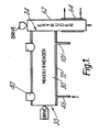
- Hydrogenated nitrile rubber is introduced in a continuous manner, into the mixing/kneading apparatus 30 through the inlet 40, near the forward end 33.
- extractant liquid is added co-currently through inlet port 46.
- the rubber/extractant mixture is mixed and kneaded in the apparatus 30.
- the temperature of the mixing/kneading zone is slightly below the boiling point of the extractant liquid.
- the moving internal surfaces of the apparatus 30 mix and knead the mixture, which is transported towards the downstream end 34.
- the extractant liquid is removed at drain 101, and the rubber is discharged through the extruder 62.
- This extruder 62 is provided with a jacket 64 through which heat transfer medium can flow.
- the extractant liquid contains residue which has been removed from the rubber.
- the rubber which is discharged from the extruder 62 is ready for final finishing (which may include devolatilization, drying and packaging).
- HNBR hydrogenated nitrile rubber
- the mixing/kneading apparatus 30 will now be described in more detail with reference to Figures 1 to 5.
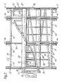
- the apparatus has an internal mixing/kneading zone and is shown in Figure 2 as consisting of three interconnected, commmercially-available AP CONTI modules 66 similar to the apparatus described in U.S. Patent 3,689,035. All the modules are not identical: they may be equipped with vent ports, drain openings and the like. However, all the modules are of otherwise similar configuration. From three to ten of such modules 66 can be interconnected to form the mixing/kneading apparatus. These modules 66 each have a housing 67 with a "Figure 8"-shaped cross-section ( Figure 4a).
- the housing 67 as a whole is provided ( Figure 2) with an outer jacket 72, for heating and cooling purposes.
- the jacket is suitably designed for handling pressurized fluids up to about 12 atmospheres at temperatures up to about 350°C.
- Spacer plate 74 is simply a metal gasket, of the same size and periphery as the ends of the modules it interconnects. It allows for free flow and communication of materials contained in the mixer, between one module and the next.
- Spacer plate 76 is a metal gasket equipped with a weir plate extending part way up from the bottom periphery and having a straight horizontal upper edge, with appropriate indentation to accommodate the shafts of the mixing/kneading apparatus, so as to provide a weir between adjacent modules, whereby hold-up and thus residence time of material in a given module can be controlled. The height of the upper edge of the spacer plate 76 may be adjusted for this purpose.
- the upstream end 33 and the downstream end 34 (Figure 1) of the apparatus are each provided with "Figure 8"-shaped flanged covers 75 and 75′ ( Figure 2).
- a transmission 77 and a drive motor 78 capable of providing variable speed rotation to each shaft.
- Each module has two hollow shafts 80, 82 rotatably mounted therein, the first mixing shaft 80 being located in the main housing portion 68 and the other, cleaning shaft 82 being parallel to the mixing shaft 80 and located in the auxiliary housing portion 70.
- packing rings 86 are located between the shafts 80, 82 and the flanged cover 75.
- shafts 80 and 82 are supported and rotate on bearings 87.
- each set of segments 88 is connected together along the leading periphery by kneading bars 90 which extend along a helical line from one end of the shaft 80 to the other. These kneading bars contact the inner surface of the main housing portion 68.
- the cleaning shaft 82 has one set of helically arranged, radially extending arms 92 with adjacent pairs of these arms 92 being interconnected by cleaning bars 94 to provide a hurdle-type arrangement. These cleaning bars 94 contact the inner surface of the auxiliary housing portion 70.
- the helical angle of the arms 92 is greater than that of the mixing shaft kneading bars 90 and is chosen so that the arms 92 of the cleaning shaft 82 mesh with and clean the sides of the disk-shaped hollow segments 88 of the mixing shaft 80 upon rotation of the two shafts 80, 82.
- the height of the upper surfaces of the cleaning bars 94 is arranged so that they can wipe the undersurface of kneading bars 90 and the surface shaft 80.
- End wall wipers 97 are optionally provided (Figure 2) at each end of the mixing shaft 80 to wipe the inside surfaces of the flanged covers 75 and 75′ Spacer plate 76 as shown in Figure 4b may be wiped with additional wipers which may be provided on the shafts for that purpose.
- the motor and transmission can drive the mixing shaft at 3-20 rpm and the cleaning shaft at 12-80 rpm.
- the speed ratio of the mixing shaft to the cleaning shaft is preferably essentially constant at from 1:2 to 1:6, most preferably at about 1:4.
- the flanged cover 75′ is provided with a vertical slot 98 extending from apex 99 to apex 100 of the "Figure-8"-shaped cross-section of the housing and with circular apertures for bearings 87 to support shafts 80 and 82.
- This slot 98 provides communication to the downwardly extending discharge extruder 62.
- a drain opening 101 indicated in Figures 1, 2 and 4a.
- This drain opening is suitably covered by a screen to retain rubber.
- This screen is most suitably made up of tri-rod or iso-rod screen bars, a wire mesh, or a plate with plurality of small holes therein.
- the discharge extruder 62 is provided with a variable speed drive (not shown) so that suitably the screw of the extruder can be driven at speeds from 10-200 rpm.
- the apparatus 30 of the preferred embodiment described above is an apparatus provided with vents, drains, etc. Material is moved downstream therein, not by the rotation and disposition of the mixing elements, but is gently pushed by the kneading bars 90 and 94, with positive discharge, out of exit slot 98 into extruder 62.
- the apparatus 30 is in no sense an extruder, because the mixing/kneading elements are not capable of compressing the rubber for the apparatus to act as an extruder.
- a hydrogenated nitrile rubber was prepared with a rhodium-based catalyst and a triphenyl phosphine based co-catalyst. Analysis of this rubber showed it to contain 116 ppm Rh and 1.46 weight per cent triphenyl phosphine.
- the rubber was introduced into an A.P. Conti machine operated in a continuous manner.
- the machine was operated at atmospheric pressure, after heating it to about 60°C and setting the main rotor speed set at 6.5 rpm and the cleaning rotor speed set at 26 rpm.
- the rubber feed rate was about 25 Kg per hour. Methanol, added counter-currently at a rate of 30 litres per hour, was used as the extractant fluid.
- Rubber was collected from the discharge end and subjected to analysis. The rhodium content was determined to be reduced to 86 ppm and the triphenyl phosphine concentration was found to be 1.18 weight per cent. A sample of the extractant fluid was also analyzed, and found to contain 15 ppm Rh and 0.04 weight per cent triphenyl phosphine.
- Rubber which was treated in the manner described in Example 1 was re-introduced into the same A.P. Conti machine, operating under the same temperature and speeds of rotation.
- the extractant fluid used in this example was thiourea-in-methanol (0.1 weight/volume per cent), and was added at a rate of 30 litres/hour.
- This example illustrates a batch extraction process.
Landscapes
- Chemical & Material Sciences (AREA)
- General Chemical & Material Sciences (AREA)
- Health & Medical Sciences (AREA)
- Chemical Kinetics & Catalysis (AREA)
- Medicinal Chemistry (AREA)
- Polymers & Plastics (AREA)
- Organic Chemistry (AREA)
- Processing And Handling Of Plastics And Other Materials For Molding In General (AREA)
- Separation, Recovery Or Treatment Of Waste Materials Containing Plastics (AREA)
- Processes Of Treating Macromolecular Substances (AREA)
Applications Claiming Priority (2)
| Application Number | Priority Date | Filing Date | Title |
|---|---|---|---|
| US07/205,813 US4857632A (en) | 1988-06-13 | 1988-06-13 | Residue removal process |
| US205813 | 1988-06-13 |
Publications (3)
| Publication Number | Publication Date |
|---|---|
| EP0346778A2 true EP0346778A2 (fr) | 1989-12-20 |
| EP0346778A3 EP0346778A3 (fr) | 1991-08-28 |
| EP0346778B1 EP0346778B1 (fr) | 1994-09-07 |
Family
ID=22763738
Family Applications (1)
| Application Number | Title | Priority Date | Filing Date |
|---|---|---|---|
| EP89110508A Expired - Lifetime EP0346778B1 (fr) | 1988-06-13 | 1989-06-10 | Procédé pour éliminer des résidus |
Country Status (4)
| Country | Link |
|---|---|
| US (1) | US4857632A (fr) |
| EP (1) | EP0346778B1 (fr) |
| CA (1) | CA1335023C (fr) |
| DE (1) | DE68918000T2 (fr) |
Cited By (1)
| Publication number | Priority date | Publication date | Assignee | Title |
|---|---|---|---|---|
| WO2004101671A1 (fr) * | 2003-05-15 | 2004-11-25 | Lanxess Deutschland Gmbh | Caoutchouc hxnbr en tant qu'agent de réticulation |
Families Citing this family (8)
| Publication number | Priority date | Publication date | Assignee | Title |
|---|---|---|---|---|
| DE4118884A1 (de) * | 1991-06-07 | 1992-12-10 | List Ag | Mischkneter |
| DE4326807A1 (de) * | 1993-08-10 | 1995-02-16 | Bayer Ag | Vollständig selbstreinigender Mischer |
| DE4339628C2 (de) * | 1993-11-20 | 2003-04-10 | Ismar Maschinen Gmbh | Knetvorrichtung |
| EP0715882B1 (fr) * | 1994-12-05 | 1998-02-25 | Bayer Ag | Réacteur-mélangeur autonettoyant pour des mélanges à haute viscosité contenant des matières solides |
| EP0715881B1 (fr) * | 1994-12-05 | 1998-02-25 | Bayer Ag | Réacteur-mélangeur complètement autonettoyant |
| US6043299A (en) | 1996-10-31 | 2000-03-28 | Shell Oil Company | Process for the extraction of material from multi-phase systems |
| CN1120850C (zh) * | 2000-03-10 | 2003-09-10 | 南帝化学工业股份有限公司 | 不饱和共聚物中加氢催化剂的脱除方法 |
| WO2017222514A1 (fr) * | 2016-06-22 | 2017-12-28 | Zeon Chemicals, Lp | Procédé de récupération d'un catalyseur d'hydrogénation résiduaire d'une solution de caoutchouc nitrile hydrogéné |
Family Cites Families (4)
| Publication number | Priority date | Publication date | Assignee | Title |
|---|---|---|---|---|
| US2786047A (en) * | 1952-02-11 | 1957-03-19 | Phillips Petroleum Co | Process for removing nickel catalyst from hydrogenated polybutadiene |
| US3531448A (en) * | 1968-11-06 | 1970-09-29 | Phillips Petroleum Co | Process for removal of hydrogenation catalyst from hyrogenated polymers |
| DE2539132C2 (de) * | 1975-09-03 | 1987-04-09 | Bayer Ag, 5090 Leverkusen | Verwendung hydrierter Dien-Copolymere als temperaturbeständige Materialien auf dem Dichtungssektor |
| US4909898A (en) * | 1986-10-01 | 1990-03-20 | Polysar Limited | Polymer recovery from solution |
-
1988
- 1988-06-13 US US07/205,813 patent/US4857632A/en not_active Expired - Lifetime
-
1989
- 1989-06-02 CA CA000601674A patent/CA1335023C/fr not_active Expired - Fee Related
- 1989-06-10 EP EP89110508A patent/EP0346778B1/fr not_active Expired - Lifetime
- 1989-06-10 DE DE68918000T patent/DE68918000T2/de not_active Expired - Fee Related
Cited By (1)
| Publication number | Priority date | Publication date | Assignee | Title |
|---|---|---|---|---|
| WO2004101671A1 (fr) * | 2003-05-15 | 2004-11-25 | Lanxess Deutschland Gmbh | Caoutchouc hxnbr en tant qu'agent de réticulation |
Also Published As
| Publication number | Publication date |
|---|---|
| CA1335023C (fr) | 1995-03-28 |
| EP0346778B1 (fr) | 1994-09-07 |
| DE68918000D1 (de) | 1994-10-13 |
| EP0346778A3 (fr) | 1991-08-28 |
| US4857632A (en) | 1989-08-15 |
| DE68918000T2 (de) | 1995-01-19 |
Similar Documents
| Publication | Publication Date | Title |
|---|---|---|
| EP0262594B1 (fr) | Récupération d'un polymère d'une solution | |
| CA1335023C (fr) | Methode d'elimination de residus | |
| US4776703A (en) | Continuous treatment apparatus for viscous material | |
| KR20000023714A (ko) | 중합체 회수 방법 | |
| AU705151B2 (en) | Method of continuous extraction of crude wax and apparatus therefor | |
| CN117654410A (zh) | 一种对氟苯甲酰氯的制备设备及其制备工艺 | |
| US6260995B1 (en) | Mixing apparatus | |
| EP0002362A1 (fr) | Event à vis pour dispositif de dégazage | |
| KR20050059146A (ko) | 액체 또는 고체 분산물로부터 물질을 추출하는 방법 및 장치 | |
| EP0187005A2 (fr) | Méthode et appareil de purification de matières liquides | |
| US3897218A (en) | Polycondensation reactor | |
| US20090053114A1 (en) | Reactor For The Treatment Of Highly Viscous Plastic Melts | |
| CN119075756B (zh) | 一种生物柴油加工用混合设备及其混合工艺 | |
| JPH05277303A (ja) | 固体抽出機 | |
| CN112642179B (zh) | 一种丁腈橡胶生产凝聚破乳消泡装置 | |
| CN221085193U (zh) | 一种磷酸三乙酯生产尾气回收装置 | |
| CN219942638U (zh) | 一种水处理药剂用混合装置 | |
| CN215388884U (zh) | 一种植物提取液加热装置 | |
| CH426735A (de) | Kombinierte Misch- und Homogenisiermaschine | |
| GB544809A (en) | Improvements relating to the manufacture of butter | |
| CN119633448B (zh) | 一种用于生产纳豆银杏叶提取物胶囊的提取装置及工艺 | |
| JPS59126411A (ja) | スチレン系重合反応物の後処理方法 | |
| CN114939388A (zh) | 一种具有多釜体内腔结构的反应釜 | |
| CN111690467A (zh) | 一种用于天然香料的萃取分离设备 | |
| JP3061296B2 (ja) | 横型高粘度液処理装置における液抜出し装置 |
Legal Events
| Date | Code | Title | Description |
|---|---|---|---|
| PUAI | Public reference made under article 153(3) epc to a published international application that has entered the european phase |
Free format text: ORIGINAL CODE: 0009012 |
|
| AK | Designated contracting states |
Kind code of ref document: A2 Designated state(s): BE DE FR GB IT NL |
|
| 17P | Request for examination filed |
Effective date: 19901205 |
|
| PUAL | Search report despatched |
Free format text: ORIGINAL CODE: 0009013 |
|
| AK | Designated contracting states |
Kind code of ref document: A3 Designated state(s): BE DE FR GB IT NL |
|
| RHK1 | Main classification (correction) |
Ipc: C08C 3/02 |
|
| 17Q | First examination report despatched |
Effective date: 19930816 |
|
| GRAA | (expected) grant |
Free format text: ORIGINAL CODE: 0009210 |
|
| AK | Designated contracting states |
Kind code of ref document: B1 Designated state(s): BE DE FR GB IT NL |
|
| PG25 | Lapsed in a contracting state [announced via postgrant information from national office to epo] |
Ref country code: NL Effective date: 19940907 Ref country code: BE Effective date: 19940907 |
|
| ITF | It: translation for a ep patent filed | ||
| REF | Corresponds to: |
Ref document number: 68918000 Country of ref document: DE Date of ref document: 19941013 |
|
| ET | Fr: translation filed | ||
| NLV1 | Nl: lapsed or annulled due to failure to fulfill the requirements of art. 29p and 29m of the patents act | ||
| PLBE | No opposition filed within time limit |
Free format text: ORIGINAL CODE: 0009261 |
|
| STAA | Information on the status of an ep patent application or granted ep patent |
Free format text: STATUS: NO OPPOSITION FILED WITHIN TIME LIMIT |
|
| 26N | No opposition filed | ||
| REG | Reference to a national code |
Ref country code: GB Ref legal event code: IF02 |
|
| PGFP | Annual fee paid to national office [announced via postgrant information from national office to epo] |
Ref country code: FR Payment date: 20040524 Year of fee payment: 16 |
|
| PGFP | Annual fee paid to national office [announced via postgrant information from national office to epo] |
Ref country code: GB Payment date: 20040609 Year of fee payment: 16 |
|
| PGFP | Annual fee paid to national office [announced via postgrant information from national office to epo] |
Ref country code: DE Payment date: 20040618 Year of fee payment: 16 |
|
| PG25 | Lapsed in a contracting state [announced via postgrant information from national office to epo] |
Ref country code: IT Free format text: LAPSE BECAUSE OF NON-PAYMENT OF DUE FEES;WARNING: LAPSES OF ITALIAN PATENTS WITH EFFECTIVE DATE BEFORE 2007 MAY HAVE OCCURRED AT ANY TIME BEFORE 2007. THE CORRECT EFFECTIVE DATE MAY BE DIFFERENT FROM THE ONE RECORDED. Effective date: 20050610 Ref country code: GB Free format text: LAPSE BECAUSE OF NON-PAYMENT OF DUE FEES Effective date: 20050610 |
|
| PG25 | Lapsed in a contracting state [announced via postgrant information from national office to epo] |
Ref country code: DE Free format text: LAPSE BECAUSE OF NON-PAYMENT OF DUE FEES Effective date: 20060103 |
|
| PG25 | Lapsed in a contracting state [announced via postgrant information from national office to epo] |
Ref country code: FR Free format text: LAPSE BECAUSE OF NON-PAYMENT OF DUE FEES Effective date: 20060228 |
|
| GBPC | Gb: european patent ceased through non-payment of renewal fee |
Effective date: 20050610 |
|
| REG | Reference to a national code |
Ref country code: FR Ref legal event code: ST Effective date: 20060228 |