EP0346575A2 - Security arrangement for a measuring device - Google Patents
Security arrangement for a measuring device Download PDFInfo
- Publication number
- EP0346575A2 EP0346575A2 EP89105337A EP89105337A EP0346575A2 EP 0346575 A2 EP0346575 A2 EP 0346575A2 EP 89105337 A EP89105337 A EP 89105337A EP 89105337 A EP89105337 A EP 89105337A EP 0346575 A2 EP0346575 A2 EP 0346575A2
- Authority
- EP
- European Patent Office
- Prior art keywords
- securing device
- parts
- designed
- carrier body
- mounting foot
- Prior art date
- Legal status (The legal status is an assumption and is not a legal conclusion. Google has not performed a legal analysis and makes no representation as to the accuracy of the status listed.)
- Granted
Links
Images

Classifications
-
- G—PHYSICS
- G01—MEASURING; TESTING
- G01D—MEASURING NOT SPECIALLY ADAPTED FOR A SPECIFIC VARIABLE; ARRANGEMENTS FOR MEASURING TWO OR MORE VARIABLES NOT COVERED IN A SINGLE OTHER SUBCLASS; TARIFF METERING APPARATUS; MEASURING OR TESTING NOT OTHERWISE PROVIDED FOR
- G01D5/00—Mechanical means for transferring the output of a sensing member; Means for converting the output of a sensing member to another variable where the form or nature of the sensing member does not constrain the means for converting; Transducers not specially adapted for a specific variable
- G01D5/26—Mechanical means for transferring the output of a sensing member; Means for converting the output of a sensing member to another variable where the form or nature of the sensing member does not constrain the means for converting; Transducers not specially adapted for a specific variable characterised by optical transfer means, i.e. using infrared, visible, or ultraviolet light
- G01D5/32—Mechanical means for transferring the output of a sensing member; Means for converting the output of a sensing member to another variable where the form or nature of the sensing member does not constrain the means for converting; Transducers not specially adapted for a specific variable characterised by optical transfer means, i.e. using infrared, visible, or ultraviolet light with attenuation or whole or partial obturation of beams of light
- G01D5/34—Mechanical means for transferring the output of a sensing member; Means for converting the output of a sensing member to another variable where the form or nature of the sensing member does not constrain the means for converting; Transducers not specially adapted for a specific variable characterised by optical transfer means, i.e. using infrared, visible, or ultraviolet light with attenuation or whole or partial obturation of beams of light the beams of light being detected by photocells
- G01D5/347—Mechanical means for transferring the output of a sensing member; Means for converting the output of a sensing member to another variable where the form or nature of the sensing member does not constrain the means for converting; Transducers not specially adapted for a specific variable characterised by optical transfer means, i.e. using infrared, visible, or ultraviolet light with attenuation or whole or partial obturation of beams of light the beams of light being detected by photocells using displacement encoding scales
- G01D5/34746—Linear encoders
- G01D5/34753—Carriages; Driving or coupling means
Definitions
- the invention relates to a multi-part safety device for a measuring device according to the preamble of claim 1.
- Such safety devices are particularly intended for the transport and assembly of measuring devices so that the sensitive components of the measuring devices are protected and the user - generally the machine tool manufacturer - can mount the measuring devices on the machine without problems.
- Such a securing device is known from DE-23 49 944 A1, which is based on US-38 33 303-A.
- An alignment arm is screwed to both a beam and a housing and positions the housing precisely with respect to the beam and thus to the scale. Thanks to the screw connections, the alignment arm can also be used repeatedly.
- the object of the invention is to provide a securing device which is constructed from simple parts and is particularly easy to assemble.
- the advantages of the safety device according to the invention are that it consists of simple plastic injection molded parts that can be attached individually to the carrier body.
- the assembly foot is gripped and secured on the end face by simply joining the two securing device parts.
- FIG. 1 shows part of a hollow body 1 of a length measuring device.
- a mounting foot 2 protrudes from the hollow body 1.
- safety devices 3 and 3 ' are arranged on both sides of the mounting base 2. With adjustment brackets 3a they support the mounting foot 2 at a sufficiently precise distance from the hollow body 1.
- the adjustment tabs 3a are attached to the securing devices 3, 3 'that a correct mounting is guaranteed in every case.
- the securing devices 3, 3 ' are anchored in the longitudinal slot 1a of the hollow profile 1 and resilient tabs 3c encompass the hollow profile 1.
- the lugs 3b form the positive connection and the resilient tabs 3c the frictional connection.
- a displacement of the mounting foot 2 is possible with moderate effort, but the mounting foot 2 remains fixed in its position relative to the hollow profile 1 in the event of vibrations and accelerations caused by transport.
- the two parts 3 and 3 ' have cooperating means on a part 3' in the form of a locking tab 3'd which engages in a recess 3d on the other part 3 of the securing device and the two parts 3, 3 'locked.
- the locking tab 3'd ends in an approach 3e with which the parts 3 and 3 'can be unlocked manually.
- the combined parts 3, 3 'of the securing device hold each other in the securing position, so that an additional fixation in the longitudinal direction can be omitted.
- the two parts 3 and 3 ' are clipped to the right and left of the mounting base 2 on the hollow body 1 and pushed in the direction of the mounting base 2 against its end faces until the adjustment tabs 3a support the mounting base 2 in the correct position. In this position, the locking tab 3'd snaps into the recess 3d and the securing device is fully assembled.
- the two parts 3 and 3 ' are unlocked manually with the aid of the extension 3e and the two parts 3 and 3' are removed from the mounting foot 2.
- FIGS. 2 and 3 show different views of the assembled safety device, which do not have to be explained in connection with FIG. 1, since they sufficiently explain the structure of the safety device to the person skilled in the art.
- Part 43 of the securing device has a receiving pocket 43d which can receive a threaded nut as an insert nut on its side facing the hollow profile. Of course, a thread can also be cut into the wall of the receiving pocket 43d.
- the counterpart - a slot tab 43'd engages in the receiving pocket 43d such that with a screw S, which is screwed through the slot of the slot tab 43'd into the thread of the nut, the two parts 43 and 43 'in the securing position are interconnected. After loosening the screw S, the parts 43 and 43 'of the securing device can be removed from the mounting foot pull off and clip off the hollow body.
- the screw can also be replaced by another locking element such as an eccentric or bayonet lock.
- the adjustment of the mounting foot is achieved by adjusting tabs 43a, which engage below the mounting foot protruding from the hollow body on a conically shaped driver M, which connects the mounting foot in a known manner to the scanning device inside the hollow body.
- the part 3, 43 or 3 ', 43' to be removed is supported by a web 3f on a leg 1c which is opposite a leg 1b when clipping off the hollow body 1.
- the legs 1b and 1c enclose the longitudinal slot 1a.
Landscapes
- Physics & Mathematics (AREA)
- General Physics & Mathematics (AREA)
- A Measuring Device Byusing Mechanical Method (AREA)
- Length Measuring Devices With Unspecified Measuring Means (AREA)
- Details Of Measuring And Other Instruments (AREA)
- Burglar Alarm Systems (AREA)
- Alarm Systems (AREA)
- Eye Examination Apparatus (AREA)
- Radar Systems Or Details Thereof (AREA)
- Spectrometry And Color Measurement (AREA)
- Orthopedics, Nursing, And Contraception (AREA)
- Measurement Of The Respiration, Hearing Ability, Form, And Blood Characteristics Of Living Organisms (AREA)
Abstract
Durch eine mehrteilige Sicherungsvorrichtung für Längenmeßeinrichtungen wird für Transport und Montage ein Montagefuß (2) in einer bestimmten Sollage zum Hohlprofil (1) fixiert. Zwei Teile (3, 3′) der Sicherungsvorrichtung weisen dazu Justierlaschen (3a, 3′a) auf, die am Montagefuß (2) angreifen. Die beiden Teile (3, 3′) werden einzeln auf den Hohlkörper (1) aufgeklipst, gegen die Stirnseiten des Montagefußes (2) verschoben und mittels einer Verriegelungslasche (3′d), die in einer Aussparung (3d) am anderen Teil (3) einrastet, vereinigt 
Description
Die Erfindung bezieht sich auf eine mehrteilige Sicherungsvorrichtung für eine Meßeinrichtung gemäß dem Oberbegriff des Anspruches 1.The invention relates to a multi-part safety device for a measuring device according to the preamble of claim 1.
Derartige Sicherungsvorrichtungen sind insbesondere für Transport und Montage von Meßeinrichtungen vorgesehen, damit die empfindlichen Bauteile der Meßeinrichtungen geschont werden und der Anwender - im allgemeinen der Werkzeugmaschinenhersteller - die Meßeinrichtungen ohne Probleme an der Maschine montieren kann.Such safety devices are particularly intended for the transport and assembly of measuring devices so that the sensitive components of the measuring devices are protected and the user - generally the machine tool manufacturer - can mount the measuring devices on the machine without problems.
Aus der DE-23 49 944 A1, die auf der US-38 33 303-A basiert, ist eine derartige Sicherungsvorrichtung bekannt. Ein Ausrichtarm ist sowohl an einem Balken als auch an einem Gehäuse verschraubt und positioniert das Gehäuse in bezug auf den Balken und damit auf den Maßstab genauestens. Durch die Verschraubungen läßt sich der Ausrichtarm auch wiederholt verwenden.Such a securing device is known from DE-23 49 944 A1, which is based on US-38 33 303-A. An alignment arm is screwed to both a beam and a housing and positions the housing precisely with respect to the beam and thus to the scale. Thanks to the screw connections, the alignment arm can also be used repeatedly.
Ferner ist aus der DE-30 20 003 C2 eine zweiteilige Sicherungsvorrichtung bekannt, die an den Stirnseiten des Montagefußes im Hohlkörper durch Schrauben verspannt wird und so den Montagefuß gegen zufälliges Verschieben sichert.Furthermore, from DE-30 20 003 C2 a two-part securing device is known, which is clamped on the end faces of the mounting foot in the hollow body by screws and thus secures the mounting foot against accidental displacement.
Nachteilig bei derartigen Sicherungsvorrichtungen ist die erforderliche Verschraubung der einzelnen Sicherungselemente.A disadvantage of such securing devices is the required screwing of the individual securing elements.
Aufgabe der Erfindung ist es, eine Sicherungsvorrichtung zu schaffen, die aus einfachen Teilen aufgebaut und besonders leicht zu montieren ist.The object of the invention is to provide a securing device which is constructed from simple parts and is particularly easy to assemble.
Diese Aufgabe wird druch eine Sicherungsvorrichtung mit den Merkmalen des Anspruches 1 gelöst.This object is achieved by a safety device with the features of claim 1.
Die Vorteile der erfindungsgemäßen Sicherungsvorrichtung liegen darin, daß sie aus einfachen Kunststoff-Spritzgußteilen besteht, die einzeln am Trägerkörper befestigt werden können. Durch einfaches Zusammenfügen der beiden Sicherungsvorrichtungsteilen wird der Montagefuß stirnseitig erfaßt und gesichert.The advantages of the safety device according to the invention are that it consists of simple plastic injection molded parts that can be attached individually to the carrier body. The assembly foot is gripped and secured on the end face by simply joining the two securing device parts.
Anhand der Zeichnungen soll mit Hilfe von Ausführungsbeispielen die Erfindung noch näher erläutert werden. Es zeigt
- Figur 1 einen Abschnitt einer Meßeinrichtung mit Sicherungsvorrichtung,
Figur 2 eine Seitenansicht der Vorrichtung in Figur 1,Figur 3 eine Draufsicht derselben und- Figur 4 eine Ansicht mit anderer Verbindungsmechanik und anderer Montagefußhalterung.
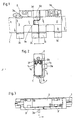
- FIG. 1 shows a section of a measuring device with a safety device,
- FIG. 2 shows a side view of the device in FIG. 1,
- Figure 3 is a plan view of the same and
- Figure 4 is a view with a different connection mechanism and different mounting foot bracket.
In der Figur 1 ist ein Teil eines Hohlkörpers 1 einer Längenmeßeinrichtung dargestellt. Ein Montagefuß 2 ragt aus dem Hohlkörper 1 heraus. Auf beiden Seiten des Montagefußes 2 sind Sicherungsvorrichtungen 3 und 3′ angeordnet. Mit Justierlaschen 3a stützen sie den Montagefuß 2 in ausreichend genauem Abstand gegenüber dem Hohlkörper 1 ab.FIG. 1 shows part of a hollow body 1 of a length measuring device. A mounting
Die Justierlaschen 3a sind so an den Sicherungsvorrichtungen 3, 3′ angebracht, daß in jedem Fall eine seitenrichtige Montage gewährleistet ist.The
Mit Ansätzen 3b sind die Sicherungsvorrichtungen 3, 3′ im Längsschlitz 1a des Hohlprofils 1 verankert und federnde Laschen 3c umgreifen das Hohlprofil 1. Die Ansätze 3b bilden den Formschluß und die federnden Laschen 3c den Kraftschluß.With
Eine Verschiebung des Montagefußes 2 ist bei mäßigem Kraftaufwand möglich, aber bei transportbedingten Erschütterungen und Beschleunigungen bleibt der Montagefuß 2 in seiner Lage zum Hohlprofil 1 fixiert.A displacement of the
Die beiden Teile 3 und 3′ verfügen über zusammenwirkende Mittel an einem Teil 3′ in Form einer Verriegelungslasche 3′d die in eine Aussparung 3d am anderen Teil 3 der Sicherungsvorrichtung eingreift und die beiden Teile 3, 3′ verriegelt. Die Verriegelungslasche 3′d endet in einem Ansatz 3e mit dem die Teile 3 und 3′ manuell entriegelt werden können.The two
Die vereinigten Teile 3, 3′ der Sicherungsvorrichtung halten sich gegenseitig in der Sicherungsposition, so daß eine zusätzliche Fixierung in Längsrichtung entfallen kann.The combined
Die beiden Teile 3 und 3′ werden zur Montage jeweils rechts und links vom Montagefuß 2 auf den Hohlkörper 1 geklipst und in Richtung auf den Montagefuß 2 gegen dessen Stirnseiten geschoben, bis die Justierlaschen 3a den Montagefuß 2 lagerichtig abstützen. In dieser Lage schnappt die Verriegelungslasche 3′d in die Aussparung 3d ein und die Sicherungsvorrichtung ist fertig montiert.The two
Zur Demontage werden die beiden Teile 3 und 3′ mit Hilfe des Ansatzes 3e manuell entriegelt und die beiden Teile 3 und 3′ vom Montagefuß 2 entfernt.For disassembly, the two
Die Figuren 2 und 3 zeigen verschiedene Ansichten der montierten Sicherungsvorrichtung, die im Zusammenhang mit der Figur 1 nicht näher erläutert werden müssen, da sie dem Fachmann den Aufbau der Sicherungsvorrichtung hinreichend verdeutlichen.FIGS. 2 and 3 show different views of the assembled safety device, which do not have to be explained in connection with FIG. 1, since they sufficiently explain the structure of the safety device to the person skilled in the art.
Beim Ausführungsbeispiel gemäß Figur 4 sind die zusammenwirkenden Mittel und die Justierlaschen anders ausgebildet. Da die übrigen Elemente nicht anders ausgestaltet sind als beim ersten Ausführungsbeispiel, sind sie nicht mit Bezugszeichen versehen worden. Teil 43 der Sicherungsvorrichtung weist eine Aufnahmetasche 43d auf, die auf ihrer dem Hohlprofil zugewandten Seite eine Gewindemutter als Einsatzmutter aufnehmen kann. Selbstverständlich kann auch in die Wandung der Aufnahmetasche 43d ein Gewinde geschnitten sein. Das Gegenstück - eine Schlitzlasche 43′d greift in die Aufnahmetasche 43d derart ein, daß mit einer Schraube S, die durch den Schlitz der Schlitzlasche 43′d in das Gewinde der Mutter eingedreht wird, die beiden Teile 43 und 43′ in der Sicherungsposition fest miteinander verbunden sind. Nach Lösen der Schraube S lassen sich die Teile 43 und 43′ der Sicherungsvorrichtung vom Montagefuß abziehen und vom Hohlkörper abklipsen.In the exemplary embodiment according to FIG. 4, the interacting means and the adjustment tabs are designed differently. Since the other elements are not configured differently than in the first exemplary embodiment, they have not been provided with reference numerals.
Selbstverständlich kann die Schraube auch durch ein anderes Verriegelungselement wie Exzenter oder Bajonettverschluß ersetzt werden.Of course, the screw can also be replaced by another locking element such as an eccentric or bayonet lock.
Bei diesem Ausführungsbeispiel wird die Justierung des Montagefußes durch Justierlaschen 43a erzielt, die unterhalb des aus dem Hohlkörper herausragenden Montagefußes an einem konisch geformten Mitnehmer M angreifen, der den Montagefuß in bekannter Weise mit der Abtasteinrichtung im Innern des Hohlkörpers verbindet. Auf eine detailiertere zeichnerische Darstellung wurde verzichtet, da dies zur Verdeutlichung der Erfindung nichts beiträgt.In this embodiment, the adjustment of the mounting foot is achieved by adjusting
Bei beiden Ausführungsbeispielen stützt sich beim Abklipsen vom Hohlkörper 1 das abzunehmende Teil 3, 43 oder 3′, 43′, über einen Steg 3f an einem Schenkel 1c ab, der einem Schenkel 1b gegenüberliegt. Die Schenkel 1b und 1c schließen den Längsschlitz 1a ein.In both exemplary embodiments, the
Claims (8)
Priority Applications (1)
| Application Number | Priority Date | Filing Date | Title |
|---|---|---|---|
| AT89105337T ATE72327T1 (en) | 1988-06-15 | 1989-03-25 | SECURITY DEVICE FOR A MEASURING DEVICE. |
Applications Claiming Priority (2)
| Application Number | Priority Date | Filing Date | Title |
|---|---|---|---|
| DE3820331A DE3820331A1 (en) | 1988-06-15 | 1988-06-15 | SECURING DEVICE FOR A MEASURING DEVICE |
| DE3820331 | 1988-06-15 |
Publications (3)
| Publication Number | Publication Date |
|---|---|
| EP0346575A2 true EP0346575A2 (en) | 1989-12-20 |
| EP0346575A3 EP0346575A3 (en) | 1990-07-04 |
| EP0346575B1 EP0346575B1 (en) | 1992-01-29 |
Family
ID=6356582
Family Applications (1)
| Application Number | Title | Priority Date | Filing Date |
|---|---|---|---|
| EP89105337A Expired - Lifetime EP0346575B1 (en) | 1988-06-15 | 1989-03-25 | Security arrangement for a measuring device |
Country Status (6)
| Country | Link |
|---|---|
| US (1) | US5036597A (en) |
| EP (1) | EP0346575B1 (en) |
| JP (1) | JP2561731B2 (en) |
| AT (1) | ATE72327T1 (en) |
| DE (2) | DE3820331A1 (en) |
| ES (1) | ES2029910T3 (en) |
Families Citing this family (5)
| Publication number | Priority date | Publication date | Assignee | Title |
|---|---|---|---|---|
| EP0841540B1 (en) * | 1996-11-11 | 2001-08-22 | Dr. Johannes Heidenhain GmbH | Length measuring device |
| DE10056947A1 (en) * | 2000-11-17 | 2002-05-23 | Optolab Licensing Gmbh | Method for mounting a material measure with dividing structures and a scanner head with scanning structures for scanning the dividing structures fastens a dividing support on a first part and the scanner head on a second part |
| US6739067B2 (en) * | 2002-04-25 | 2004-05-25 | Acu-Rite, Inc. | Cover for a sealed linear encoder and a sealed linear encoder |
| US6868620B2 (en) | 2002-08-01 | 2005-03-22 | Solar Wide Industrial, Ltd. | Digital measuring instrument having flexible measuring line |
| DE10262008B4 (en) | 2002-10-25 | 2010-08-19 | Dr. Johannes Heidenhain Gmbh | length measuring system |
Family Cites Families (7)
| Publication number | Priority date | Publication date | Assignee | Title |
|---|---|---|---|---|
| US3833303A (en) * | 1972-10-06 | 1974-09-03 | Bausch & Lomb | Measuring apparatus using the moire fringe concept of measurement |
| US3942895A (en) * | 1973-09-04 | 1976-03-09 | Teledyne, Inc. | Linear digital readout assembly for milling machines and the like and means for mounting same |
| US4031595A (en) * | 1975-09-02 | 1977-06-28 | Bausch & Lomb Incorporated | High precision incremental distance measuring system |
| IT1113652B (en) * | 1977-10-17 | 1986-01-20 | Sits Soc It Telecom Siemens | PACKAGING IN PLASTIC MATERIAL |
| DE3020003C2 (en) * | 1980-05-24 | 1983-01-27 | Dr. Johannes Heidenhain Gmbh, 8225 Traunreut | Safety device for transport and assembly of a measuring device |
| DE3302643C2 (en) * | 1983-01-27 | 1987-01-08 | Dr. Johannes Heidenhain Gmbh, 8225 Traunreut | Clamping device for a length measuring device |
| JPS6135734U (en) * | 1984-08-02 | 1986-03-05 | 株式会社 測機舎 | Mounting mechanism of magnetic scale device |
-
1988
- 1988-06-15 DE DE3820331A patent/DE3820331A1/en active Granted
-
1989
- 1989-03-25 AT AT89105337T patent/ATE72327T1/en not_active IP Right Cessation
- 1989-03-25 EP EP89105337A patent/EP0346575B1/en not_active Expired - Lifetime
- 1989-03-25 ES ES198989105337T patent/ES2029910T3/en not_active Expired - Lifetime
- 1989-03-25 DE DE8989105337T patent/DE58900791D1/en not_active Expired - Fee Related
- 1989-06-15 JP JP1150664A patent/JP2561731B2/en not_active Expired - Lifetime
-
1990
- 1990-12-11 US US07/625,709 patent/US5036597A/en not_active Expired - Lifetime
Also Published As
| Publication number | Publication date |
|---|---|
| JPH0238911A (en) | 1990-02-08 |
| ES2029910T3 (en) | 1992-10-01 |
| DE3820331A1 (en) | 1989-12-21 |
| DE58900791D1 (en) | 1992-03-12 |
| JP2561731B2 (en) | 1996-12-11 |
| EP0346575B1 (en) | 1992-01-29 |
| US5036597A (en) | 1991-08-06 |
| DE3820331C2 (en) | 1990-05-03 |
| EP0346575A3 (en) | 1990-07-04 |
| ATE72327T1 (en) | 1992-02-15 |
Similar Documents
| Publication | Publication Date | Title |
|---|---|---|
| DE4110503C2 (en) | Lighting device, in particular for displays of data processing devices | |
| DE9217377U1 (en) | Arrangement for spring-elastic securing of fastening elements in recesses | |
| AT416U1 (en) | CONNECTING FITTING FOR FASTENING THE RAILING OF A DRAWER TO A REAR OR SIDE WALL OF THE DRAWER | |
| EP0961535A1 (en) | Distance piece for mouting a pcb onto an electrically conductive carrier | |
| DE29908612U1 (en) | Terminal block | |
| DE4032865C2 (en) | Screw connection | |
| EP0346575B1 (en) | Security arrangement for a measuring device | |
| DE2215707C3 (en) | Clamping device | |
| DE8627319U1 (en) | Segment for aligning a mold plate on a machine tool table | |
| EP0431209A1 (en) | Device for clamping rails or the like | |
| DE2652672C2 (en) | Device for fastening a housing for electrical devices in an opening in a control panel | |
| EP1507684B1 (en) | Holding element for mounting metal frame nets, especially lateral trunk nets | |
| DE4132267C2 (en) | Fixing device for license plates within a license plate amplifier | |
| DE19901980B4 (en) | display module | |
| EP0253093B1 (en) | Device for fixing a bearing area of a ski binding part to a ski | |
| DE8816863U1 (en) | Safety device for a measuring device | |
| EP1617087A1 (en) | Supporting device | |
| EP1459938B1 (en) | Fastener for releasably attaching a member to a carrier | |
| DE9301520U1 (en) | Device for fastening installation elements | |
| DE9104081U1 (en) | Construction fence element with traffic control device | |
| EP0337226A1 (en) | Supporting rail | |
| EP0609973A1 (en) | Device for fixing of angled coverbrackets | |
| DE29611021U1 (en) | Bracket for attaching an object | |
| EP0542007B1 (en) | Device to link constructional profiles and/or similar parts, especially for flexible assembly systems | |
| DE3722996C2 (en) | Door arrester for a vehicle door |
Legal Events
| Date | Code | Title | Description |
|---|---|---|---|
| PUAI | Public reference made under article 153(3) epc to a published international application that has entered the european phase |
Free format text: ORIGINAL CODE: 0009012 |
|
| 17P | Request for examination filed |
Effective date: 19890407 |
|
| AK | Designated contracting states |
Kind code of ref document: A2 Designated state(s): AT CH DE ES FR GB IT LI NL SE |
|
| PUAL | Search report despatched |
Free format text: ORIGINAL CODE: 0009013 |
|
| AK | Designated contracting states |
Kind code of ref document: A3 Designated state(s): AT CH DE ES FR GB IT LI NL SE |
|
| 17Q | First examination report despatched |
Effective date: 19910709 |
|
| ITF | It: translation for a ep patent filed | ||
| GRAA | (expected) grant |
Free format text: ORIGINAL CODE: 0009210 |
|
| AK | Designated contracting states |
Kind code of ref document: B1 Designated state(s): AT CH DE ES FR GB IT LI NL SE |
|
| REF | Corresponds to: |
Ref document number: 72327 Country of ref document: AT Date of ref document: 19920215 Kind code of ref document: T |
|
| PGFP | Annual fee paid to national office [announced via postgrant information from national office to epo] |
Ref country code: SE Payment date: 19920217 Year of fee payment: 4 |
|
| ET | Fr: translation filed | ||
| GBT | Gb: translation of ep patent filed (gb section 77(6)(a)/1977) | ||
| REF | Corresponds to: |
Ref document number: 58900791 Country of ref document: DE Date of ref document: 19920312 |
|
| PGFP | Annual fee paid to national office [announced via postgrant information from national office to epo] |
Ref country code: NL Payment date: 19920331 Year of fee payment: 4 |
|
| REG | Reference to a national code |
Ref country code: ES Ref legal event code: FG2A Ref document number: 2029910 Country of ref document: ES Kind code of ref document: T3 |
|
| PLBE | No opposition filed within time limit |
Free format text: ORIGINAL CODE: 0009261 |
|
| STAA | Information on the status of an ep patent application or granted ep patent |
Free format text: STATUS: NO OPPOSITION FILED WITHIN TIME LIMIT |
|
| 26N | No opposition filed | ||
| PG25 | Lapsed in a contracting state [announced via postgrant information from national office to epo] |
Ref country code: SE Effective date: 19930326 |
|
| PG25 | Lapsed in a contracting state [announced via postgrant information from national office to epo] |
Ref country code: NL Effective date: 19931001 |
|
| NLV4 | Nl: lapsed or anulled due to non-payment of the annual fee | ||
| EUG | Se: european patent has lapsed |
Ref document number: 89105337.3 Effective date: 19931008 |
|
| PGFP | Annual fee paid to national office [announced via postgrant information from national office to epo] |
Ref country code: AT Payment date: 20010226 Year of fee payment: 13 |
|
| PGFP | Annual fee paid to national office [announced via postgrant information from national office to epo] |
Ref country code: FR Payment date: 20010313 Year of fee payment: 13 |
|
| PGFP | Annual fee paid to national office [announced via postgrant information from national office to epo] |
Ref country code: ES Payment date: 20010316 Year of fee payment: 13 |
|
| REG | Reference to a national code |
Ref country code: GB Ref legal event code: IF02 |
|
| PGFP | Annual fee paid to national office [announced via postgrant information from national office to epo] |
Ref country code: GB Payment date: 20020315 Year of fee payment: 14 |
|
| PGFP | Annual fee paid to national office [announced via postgrant information from national office to epo] |
Ref country code: CH Payment date: 20020319 Year of fee payment: 14 |
|
| PG25 | Lapsed in a contracting state [announced via postgrant information from national office to epo] |
Ref country code: AT Free format text: LAPSE BECAUSE OF NON-PAYMENT OF DUE FEES Effective date: 20020325 |
|
| PG25 | Lapsed in a contracting state [announced via postgrant information from national office to epo] |
Ref country code: ES Free format text: LAPSE BECAUSE OF NON-PAYMENT OF DUE FEES Effective date: 20020326 |
|
| PG25 | Lapsed in a contracting state [announced via postgrant information from national office to epo] |
Ref country code: FR Free format text: LAPSE BECAUSE OF NON-PAYMENT OF DUE FEES Effective date: 20021129 |
|
| REG | Reference to a national code |
Ref country code: FR Ref legal event code: ST |
|
| PG25 | Lapsed in a contracting state [announced via postgrant information from national office to epo] |
Ref country code: GB Free format text: LAPSE BECAUSE OF NON-PAYMENT OF DUE FEES Effective date: 20030325 |
|
| PG25 | Lapsed in a contracting state [announced via postgrant information from national office to epo] |
Ref country code: LI Free format text: LAPSE BECAUSE OF NON-PAYMENT OF DUE FEES Effective date: 20030331 Ref country code: CH Free format text: LAPSE BECAUSE OF NON-PAYMENT OF DUE FEES Effective date: 20030331 |
|
| GBPC | Gb: european patent ceased through non-payment of renewal fee |
Effective date: 20030325 |
|
| REG | Reference to a national code |
Ref country code: CH Ref legal event code: PL |
|
| PGFP | Annual fee paid to national office [announced via postgrant information from national office to epo] |
Ref country code: DE Payment date: 20040305 Year of fee payment: 16 |
|
| REG | Reference to a national code |
Ref country code: ES Ref legal event code: FD2A Effective date: 20030410 |
|
| PG25 | Lapsed in a contracting state [announced via postgrant information from national office to epo] |
Ref country code: IT Free format text: LAPSE BECAUSE OF NON-PAYMENT OF DUE FEES;WARNING: LAPSES OF ITALIAN PATENTS WITH EFFECTIVE DATE BEFORE 2007 MAY HAVE OCCURRED AT ANY TIME BEFORE 2007. THE CORRECT EFFECTIVE DATE MAY BE DIFFERENT FROM THE ONE RECORDED. Effective date: 20050325 |
|
| PG25 | Lapsed in a contracting state [announced via postgrant information from national office to epo] |
Ref country code: DE Free format text: LAPSE BECAUSE OF NON-PAYMENT OF DUE FEES Effective date: 20051001 |