EP0346503A1 - Programmiergriff - Google Patents
Programmiergriff Download PDFInfo
- Publication number
- EP0346503A1 EP0346503A1 EP88109325A EP88109325A EP0346503A1 EP 0346503 A1 EP0346503 A1 EP 0346503A1 EP 88109325 A EP88109325 A EP 88109325A EP 88109325 A EP88109325 A EP 88109325A EP 0346503 A1 EP0346503 A1 EP 0346503A1
- Authority
- EP
- European Patent Office
- Prior art keywords
- sleeve
- longitudinal axis
- programming device
- programming
- slide
- Prior art date
- Legal status (The legal status is an assumption and is not a legal conclusion. Google has not performed a legal analysis and makes no representation as to the accuracy of the status listed.)
- Granted
Links
- 238000006073 displacement reaction Methods 0.000 claims description 4
- 230000001419 dependent effect Effects 0.000 description 1
- 238000001514 detection method Methods 0.000 description 1
- 230000001939 inductive effect Effects 0.000 description 1
- 210000002105 tongue Anatomy 0.000 description 1
Images

Classifications
-
- B—PERFORMING OPERATIONS; TRANSPORTING
- B25—HAND TOOLS; PORTABLE POWER-DRIVEN TOOLS; MANIPULATORS
- B25J—MANIPULATORS; CHAMBERS PROVIDED WITH MANIPULATION DEVICES
- B25J13/00—Controls for manipulators
- B25J13/02—Hand grip control means
Definitions
- the invention relates to a programming device according to the preamble of claim 1.
- the springs consist of tongues on which strain gauges are arranged.
- the springs consist of leaf springs, which are each arranged between two inductive sensors. The leaf springs clamped on the middle part each have a ball at their ends, against which two stops of the sleeve rest.
- Both embodiments have the disadvantage that the springs are deformed in an arc shape and thus the displacement sensors measure arcuate deformations. Another disadvantage is that measured values that are not correctly corrected are obtained when moving in the different axis directions. A further disadvantage is that the forces that must be exerted on the sleeve in order to deform the springs by a certain amount are predetermined by the spring characteristics of the springs. However, it is desirable to vary these forces depending on whether the load that the manipulator member to be programmed is moving is light or heavy.
- the object is to improve the programming device in such a way that undistorted measured values are obtained during real movements between the sleeve and the middle part in the different axial directions.
- the programming device has a central part 1, which can be rigidly connected to the member of the handling device to be programmed via a connecting plate 21.
- This middle part 1 is surrounded by a sleeve 2, which has a square cross section.
- the central part 1 has a longitudinal axis 17.
- the measuring systems 24 and 25, which are also arranged at a distance from one another along the axis 17, are used to program movements in the direction of the Y axis and of rotary movements dx.
- the measuring systems 24 and 25 are offset from the measuring systems 22 and 23 by 90 ° about the axis 17.
- the measuring systems 22 to 25 are identical to one another and their structure will be explained with reference to FIG. 3.
- the sleeve 2 surrounds the middle part 1 with play.
- a board 26 of the middle part which runs transversely to the axis 17, two legs 9 of a slide bearing are arranged, between which a shaft 7 runs.
- a slide 6 is slidably mounted on the shaft 7.
- Inserts 4 are screwed into the sleeve 2 in mutually opposite walls, each carrying a pin 5, which extend in the direction of the longitudinal axis 17.
- the ends of the pins 5 have plane-parallel surfaces, between which a ball 8 of the slide 6 is arranged with as little play as possible. Since absolute freedom from play cannot be achieved, a spring 10 is arranged on the shaft 7, which is supported on the one hand on the slide 6 and on the other hand on one of the legs 9.
- the pins 5 are surrounded by coil springs 3, which are supported on the one hand on the sleeve 2 and on the other hand on the legs 9. If pressure is exerted on the sleeve 2 in the direction of the arrow Y or counter to this direction of the arrow, the slide 6 is displaced linearly via the pins 5.
- a path sensor (not shown) is arranged on the circuit board 1, which then measures the relative movement between the carriage 6 and the circuit board 26 and converts it into electrical signals.
- the legs 9 of the slide bearing have bores through which the pins 5 run. Since the inserts 4 can be unscrewed, it is possible to use the coil springs 3 to be replaced by those with a steeper or flatter spring characteristic.
- a further measuring system 27 is arranged between the measuring systems 24 and 25 and serves for the detection of relative movements between the sleeve 2 and the central part 1 in the direction of the Z axis.
- This measuring system 27 comprises a fork 19 which is attached to the sleeve 2. This fork extends inwards to the longitudinal axis 17.
- the fork 19 comprises a ball 20 of a carriage 18 which is mounted on a shaft 28 which runs parallel to the longitudinal axis 17 and which runs between the plates 26. If there is a relative movement between the middle part 1 and the sleeve 2 in the direction of arrow Z or counter to this direction of the arrow, then the slide 18 is displaced linearly.
- a displacement sensor is arranged on the board 29, which detects the movements of the carriage 18 relative to the board 29.
- the slide bearings are each U-shaped and have a flat central leg 29, over which a flat side of a slide 6 slides, whereby the slide 6 is rotatably mounted on the shafts 7. This also applies to the flat side of the slide 18 with respect to the board 29.
- a further measuring system 30 is provided.
- This measuring system has a gimbal 11 surrounding the axis 17, which is supported by two first bearing pins 12 which are fastened to two diametrically opposite walls of the sleeve 2. These bearing pins 12 run coaxially with one another.
- the gimbal 11 is slidably supported by the bearing pins 12.
- Two further bearing pins 13 are fastened to a middle piece 14 and run at right angles to the bearing pins 13.
- These bearing pins 13 likewise run through the gimbal ring 11, which can be displaced along these pins 13.
- the center piece 14 is supported by a journal 31 of the central part 1, is rotatable about this journal 31 and displaceable along this journal.
- the bearing journal 31 surrounds the longitudinal axis 17.
- the middle piece 14 has an arm 15 which extends outside the longitudinal axis 17. Between this arm 15 and the central part 1, two helical springs 16 are arranged, which are interchangeable via inserts 32 and 33 on the central part 1 and the sleeve 2.
Landscapes
- Engineering & Computer Science (AREA)
- Robotics (AREA)
- Mechanical Engineering (AREA)
- A Measuring Device Byusing Mechanical Method (AREA)
- Length Measuring Devices With Unspecified Measuring Means (AREA)
- Aerodynamic Tests, Hydrodynamic Tests, Wind Tunnels, And Water Tanks (AREA)
- Manipulator (AREA)
- Testing Of Devices, Machine Parts, Or Other Structures Thereof (AREA)
- Sampling And Sample Adjustment (AREA)
Abstract
Description
- Die Erfindung betrifft eine Programmiervorrichtung nach dem Oberbegriff des Anspruches 1.
- Eine solche Programmiervorrichtung ist Gegenstand der CH-A 639 310. Nach einer ersten Ausführungsform bestehen die Federn aus Zungen, auf denen Dehnmeßstreifen angeordnet sind. Nach einer zweiten Ausführungsform bestehen die Federn aus Blattfedern, die jeweils zwischen zwei induktiven Meßwertgebern angeordnet sind. Die am Mittelteil eingespannten Blattfedern tragen an Ihren Enden jeweils eine Kugel, gegen die jeweils zwei Anschläge der Hülse anliegen.
- Beiden Ausführungsformen haftet der Nachteil an, daß die Federn bogenförmig deformiert werden und damit die Wegsensoren bogenförmige Deformationen messen. Ein weiterer Nachteil besteht darin, daß bei Bewegungen in den verschiedenen Achsrichtungen, nicht einwandfrei entzerrte Meßwerte erhalten werden. Nachteilig ist weiterhin, daß die Kräfte, die auf die Hülse ausgeübt werden müssen, um die Federn um ein bestimmtes Maß zu deformieren, durch die Federkennlinien der Federn vorgegeben sind. Es ist jedoch wünschenswert, diese Kräfte zu variieren, je nachdem, ob die Last, die das zu programmierende Glied des Handhabungsgeräts bewegt leicht oder schwer ist.
- Es besteht die Aufgabe, die Programmiervorrichtung so zu verbessern, daß unverzerrte Meßwerte bei Realtivbewegungen zwischen Hülse und Mittelteil in den verschiedenen Achsrichtungen erhalten werden.
- Gelöst wird diese Aufgabe mit den kennzeichnenden Merkmalen des Anspruches 1. Vorteilhafte Ausgestaltungen sind den Unteransprüchen entnehmbar.
- Ein Ausführungsbeispiel wird nachfolgend anhand der Zeichnungen näher erläutert. Es zeigen:
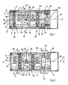
- Fig. 1 einen Längsschnitt durch die Programmiervorrichtung längs der Linie I-I in Fig. 2;
- Fig. 2 einen Längsschnitt durch die Programmiervorrichtung längs der Linie II-II in Fig. 1;
- Fig. 3 einen Querschnitt längs der Linie A-A in Fig. 2;
- Fig. 4 einen Querschnitt längs der Linie B-B in Fig. 2 und
- Fig. 5 einen Querschnitt längs der Linie C-C in Fig. 2.
- Die Programmiervorrichtung weist ein Mittelteil 1 auf, das über eine Anschlußplatte 21 starr mit dem zu programmierenden Glied des Handhabungsgeräts verbunden werden kann. Dieses Mittelteil 1 wird umgeben von einer Hülse 2, welche einen quadratischen Querschnitt aufweist. Das Mittelteil 1 weist eine Längsachse 17 auf.
- Mit der Programmiervorrichtung gemäß dem Ausführungsbeispiel können Relativbewegungen zwischen dem Mittelteil 1 und der Hülse 2 in Richtung der Achsen X, Y und Z sowie Drehbewegungen dx, dy und dz um diese Achsen programmiert werden, wobei die Achsen X und Y rechtwinklig zueinander und zur Z Achse verlaufen, wobei letztere identisch ist mit der Längsachse 17 des Mittelteils 1.
- Zur Programmierung von Bewegungen in Richtung der Achse X und zur Programmierung von Drehbewegungen dy dienen die Meßsysteme 22 und 23, die im Abstand zueinander längs der Achse 17 angeordnet sind. Zur Programmierung von Bewegungen in Richtung der Achse Y und von Drehbewegungen dx dienen die Meßsysteme 24 und 25, die ebenfalls im Abstand zueinander längs der Achse 17 angeordnet sind. Die Meßsysteme 24 und 25 sind um 90° um die Achse 17 versetzt zu den Meßsystemen 22 und 23 angeordnet. Die Meßsysteme 22 bis 25 sind zueinander identisch und werden in ihrem Aufbau anhand der Fig. 3 erläutert.
- Die Hülse 2 umgibt das Mittelteil 1 mit Spiel. Auf einer Platine 26 des Mittelteils, die quer zur Achse 17 verläuft, sind zwei Schenkel 9 einer Schlittenlagerung angeordnet, zwischen denen eine Welle 7 verläuft. Auf der Welle 7 ist verschiebbar ein Schlitten 6 gelagert. In die Hülse 2 sind in einander gegenüberliegenden Wandungen Einsätze 4 eingeschraubt, die jeweils einen Stift 5 tragen, die sich in Richtung der Längsachse 17 erstrecken. Die Enden der Stifte 5 weisen planparallele Flächen auf, zwischen denen eine Kugel 8 des Schlittens 6 möglichst spielfrei angeordnet ist. Da eine absolute Spielfreiheit nicht erzielbar ist, ist auf der Welle 7 eine Feder 10 angeordnet, welche sich einerseits am Schlitten 6 und andererseits an einem der Schenkel 9 abstützt. Die Stifte 5 werden umgeben von Wendelfedern 3, welche sich einerseits an der Hülse 2 und andererseits an den Schenkeln 9 abstützen. Wird ein Druck auf die Hülse 2 in Pfeilrichtung Y oder entgegen dieser Pfeilrichtung ausgeübt, dann wird der Schlitten 6 über die Stifte 5 linear verschoben. Auf der Platine 1 ist ein nicht dargestellter Wegsensor angeordnet, der dann die Relativbewegung zwischen dem Schlitten 6 und der Platine 26 mißt und in elektrische Signale umsetzt.
- Die Schenkel 9 der Schlittenlagerung weisen Bohrungen auf, durch welche die Stifte 5 verlaufen. Da die Einsätze 4 herausschraubbar sind, ist es möglich, die Wendelfedern 3 gegen solche mit einer steileren oder flacheren Federkennlinie auszutauschen.
- Bei Relativbewegungen zwischen Mittelteil 1 und Hülse 2 in Richtung der Achse X werden die Schlitten 6A und 6B der Meßsysteme 22 und 23 in gleicher Richtung verschoben. Bei Drehbewegungen dy um die Achse Y werden die Schlitten 6A und 6B in entgegengesetzter Richtung verschoben. Entsprechendes gilt für die Schlitten 6C und 6D bei einer Linearbewegung in Richtung der Achse Y bzw. bei einer Drehbewegung dx um die Achse X. Die Bewegungen der Schlitten 6A bis 6D werden jeweils durch die vorerwähnten Wegsensoren erfaßt.
- Zwischen den Meßsystemen 24 und 25 ist ein weiteres Meßsystem 27 angeordnet, das der Erfassung von Relativbewegungen zwischen Hülse 2 und Mittelteil 1 in Richtung der Achse Z dient. Dieses Meßsystem 27 umfaßt eine Gabel 19, die an der Hülse 2 befestigt ist. Diese Gabel erstreckt sich nach innen bis zur Längsachse 17. Die Gabel 19 umfaßt eine Kugel 20 eines Schlittens 18, der auf einer parallel zur Längsachse 17 verlaufenden Welle 28 gelagert ist, welche zwischen den Platinen 26 verläuft. Findet eine Relativbewegung zwischen dem Mittelteil 1 und der Hülse 2 in Pfeilrichtung Z oder entgegen dieser Pfeilrichtung statt, dann wird der Schlitten 18 linear verschoben. An der Platine 29 ist wiederum ein Wegsensor angeordnet, der die Bewegungen des Schlittens 18 relativ zur Platine 29 erfaßt.
- Die Schlittenlagerungen sind jeweils u-förmig ausgebildet und weisen einen flachen Mittelschenkel 29 auf, über den jeweils eine Flachseite eines Schlittens 6 gleitet, wodurch die Schlitten 6 verdrehfest auf den Wellen 7 gelagert sind. Dies gilt auch bezüglich der Flachseite des Schlittens 18 in bezug auf die Platine 29.
- In Normallage, wenn keine Kräfte auf die Hülse 2 ausgeübt werden, liegen alle Kugeln 8, 20 auf der Längsachse 17.
- Um Drehbewegungen dz um die Achse Z zu erfassen, ist ein weiteres Meßsystem 30 vorgesehen. Dieses Meßsystem weist einen die Achse 17 umgebenden Kardanring 11 auf, der von zwei ersten Lagerstiften 12 gelagert wird, die an zwei einander diametral gegenüberliegenden Wandungen der Hülse 2 befestigt sind. Diese Lagerstifte 12 verlaufen koaxial zueinander. Der Kardanring 11 wird von den Lagerstiften 12 verschiebbar gelagert. Zwei weitere Lagerstifte 13 sind an einem Mittelstück 14 befestigt und verlaufen rechtwinklig zu den Lagerstiften 13. Diese Lagerstifte 13 verlaufen ebenfalls durch den Kardanring 11 hindurch, welcher längs dieser Stifte 13 verschiebbar ist. Das Mittelstück 14 wird von einem Lagerzapfen 31 des Mittelteils 1 gelagert, ist um diesen Lagerzapfen 31 drehbar und längs dieses Lagerzapfens verschiebbar. Der Lagerzapfen 31 umgibt die Längsachse 17.
- Das Mittelstück 14 weist einen Arm 15 auf, der außerhalb der Längsachse 17 verläuft. Zwischen diesem Arm 15 und dem Mittelteil 1 sind jeweils zwei Wendelfedern 16 angeordnet, welche über Einsätze 32 und 33 am Mittelteil 1 bzw. der Hülse 2 austauschbar sind.
- Wegen des relativ zu den Lagerstiften 12 und 13 verschiebbaren Kardanringes 11 werden keine Relativbewegungen zwischen dem Mittelteil 1 und der Hülse 2 in den Achsen X und Y und Drehbewegungen um diese Achsen herum auf das Mittelstück 14 übertragen. Übertragen werden jedoch Drehbewegungen dz um die Achse Z, die sich in einer Drehbewegung des Arms 15 um die Achse 17 auswirken, die von einem dort am Mittelteil 1 angeordneten Wegsensor erfaßt werden.
Claims (13)
Priority Applications (8)
| Application Number | Priority Date | Filing Date | Title |
|---|---|---|---|
| EP88109325A EP0346503B1 (de) | 1988-06-11 | 1988-06-11 | Programmiergriff |
| AT88109325T ATE77787T1 (de) | 1988-06-11 | 1988-06-11 | Programmiergriff. |
| DE8888109325T DE3872516D1 (de) | 1988-06-11 | 1988-06-11 | Programmiergriff. |
| ES198888109325T ES2034032T3 (es) | 1988-06-11 | 1988-06-11 | Dispositivo programador. |
| SU894614166A RU1814610C (ru) | 1988-06-11 | 1989-05-29 | Программирующее устройство дл манипул тора |
| US07/360,095 US4965939A (en) | 1988-06-11 | 1989-06-01 | Programming handle |
| JP1146907A JPH0288189A (ja) | 1988-06-11 | 1989-06-12 | プログラム制御用手動操作器具 |
| GR920402212T GR3005880T3 (de) | 1988-06-11 | 1992-10-01 |
Applications Claiming Priority (1)
| Application Number | Priority Date | Filing Date | Title |
|---|---|---|---|
| EP88109325A EP0346503B1 (de) | 1988-06-11 | 1988-06-11 | Programmiergriff |
Publications (2)
| Publication Number | Publication Date |
|---|---|
| EP0346503A1 true EP0346503A1 (de) | 1989-12-20 |
| EP0346503B1 EP0346503B1 (de) | 1992-07-01 |
Family
ID=8199048
Family Applications (1)
| Application Number | Title | Priority Date | Filing Date |
|---|---|---|---|
| EP88109325A Expired - Lifetime EP0346503B1 (de) | 1988-06-11 | 1988-06-11 | Programmiergriff |
Country Status (8)
| Country | Link |
|---|---|
| US (1) | US4965939A (de) |
| EP (1) | EP0346503B1 (de) |
| JP (1) | JPH0288189A (de) |
| AT (1) | ATE77787T1 (de) |
| DE (1) | DE3872516D1 (de) |
| ES (1) | ES2034032T3 (de) |
| GR (1) | GR3005880T3 (de) |
| RU (1) | RU1814610C (de) |
Cited By (1)
| Publication number | Priority date | Publication date | Assignee | Title |
|---|---|---|---|---|
| DE4408128A1 (de) * | 1994-03-10 | 1995-09-21 | Siemens Ag | Bediengriff eines medizinischen Gerätes |
Citations (3)
| Publication number | Priority date | Publication date | Assignee | Title |
|---|---|---|---|---|
| US2866333A (en) * | 1956-04-04 | 1958-12-30 | Intavex Inc | Plural axis dynamometer |
| FR2434426A1 (fr) * | 1978-07-06 | 1980-03-21 | Renault | Dispositif manuel de commande de robot |
| DE3211992A1 (de) * | 1982-03-31 | 1983-10-06 | Wagner Gmbh J | Verfahren und vorrichtung zum programmieren eines roboters, insbesondere farbspritzroboters |
Family Cites Families (2)
| Publication number | Priority date | Publication date | Assignee | Title |
|---|---|---|---|---|
| US3990153A (en) * | 1972-01-25 | 1976-11-09 | Michel Calame | Automatic measurement of workpieces |
| US4536961A (en) * | 1983-03-31 | 1985-08-27 | Meseltron S. A. | Three-dimensional measuring device |
-
1988
- 1988-06-11 ES ES198888109325T patent/ES2034032T3/es not_active Expired - Lifetime
- 1988-06-11 EP EP88109325A patent/EP0346503B1/de not_active Expired - Lifetime
- 1988-06-11 AT AT88109325T patent/ATE77787T1/de not_active IP Right Cessation
- 1988-06-11 DE DE8888109325T patent/DE3872516D1/de not_active Expired - Fee Related
-
1989
- 1989-05-29 RU SU894614166A patent/RU1814610C/ru active
- 1989-06-01 US US07/360,095 patent/US4965939A/en not_active Expired - Fee Related
- 1989-06-12 JP JP1146907A patent/JPH0288189A/ja active Pending
-
1992
- 1992-10-01 GR GR920402212T patent/GR3005880T3/el unknown
Patent Citations (3)
| Publication number | Priority date | Publication date | Assignee | Title |
|---|---|---|---|---|
| US2866333A (en) * | 1956-04-04 | 1958-12-30 | Intavex Inc | Plural axis dynamometer |
| FR2434426A1 (fr) * | 1978-07-06 | 1980-03-21 | Renault | Dispositif manuel de commande de robot |
| DE3211992A1 (de) * | 1982-03-31 | 1983-10-06 | Wagner Gmbh J | Verfahren und vorrichtung zum programmieren eines roboters, insbesondere farbspritzroboters |
Cited By (2)
| Publication number | Priority date | Publication date | Assignee | Title |
|---|---|---|---|---|
| DE4408128A1 (de) * | 1994-03-10 | 1995-09-21 | Siemens Ag | Bediengriff eines medizinischen Gerätes |
| US5585608A (en) * | 1994-03-10 | 1996-12-17 | Siemens Aktiengesellschaft | Operating handle including switches and pressure sensors for medical equipment |
Also Published As
| Publication number | Publication date |
|---|---|
| JPH0288189A (ja) | 1990-03-28 |
| DE3872516D1 (de) | 1992-08-06 |
| US4965939A (en) | 1990-10-30 |
| ATE77787T1 (de) | 1992-07-15 |
| GR3005880T3 (de) | 1993-06-07 |
| ES2034032T3 (es) | 1993-04-01 |
| RU1814610C (ru) | 1993-05-07 |
| EP0346503B1 (de) | 1992-07-01 |
Similar Documents
| Publication | Publication Date | Title |
|---|---|---|
| EP0499943B1 (de) | Prüfvorrichtung zur Durchführung von 4-Punkt-Biegewechselbeanspruchungsversuchen | |
| DE4207661C2 (de) | Meßvorrichtung für die Form oder die Position eines Objekts | |
| DE69211210T2 (de) | Kalibriervorrichtung für Maschine | |
| DE69927621T2 (de) | Messkopf zum Kontrollieren linearer Dimensionen mit einstellbarer Feder | |
| EP0144803B1 (de) | Berührungsfreie Messvorrichtung für Drehmoment und/oder Drehwinkel | |
| DE10243596B4 (de) | Linearer Aktuator mit zwei durch Verbindungsstäbe verbundenen Drehelementen und einem Hauptkörper aus zwei getrennten Rahmen | |
| DE3804242C2 (de) | ||
| CH659704A5 (de) | Vorrichtung zum messen von dimensionen eines werkstueckes mit einem traeger. | |
| DE3426315C2 (de) | Zahnmeßtaster | |
| DE60017800T2 (de) | Linearer tastkopf für axiale bewegung | |
| DE2915992C2 (de) | ||
| DE7739666U1 (de) | Vielgliedriger arm fuer einen roboter oder automaten | |
| DE2613995A1 (de) | Lagerbaugruppe fuer messgeraete | |
| DE2445835A1 (de) | Bewegliches messystem fuer eine messlehre vom direkt beruehrenden typ | |
| DE19534063C2 (de) | Winkelmeßeinrichtung | |
| DE3026353A1 (de) | Messinstrument zur ueberpruefung von linearen abmessungen | |
| EP0346503B1 (de) | Programmiergriff | |
| DE19703735C2 (de) | Längenveränderliches Element | |
| EP0615110B1 (de) | Mobile koordinatenmessmaschine und kalibrierverfahren | |
| DE3438718A1 (de) | Praezisionskupplung fuer die winkelgetreue uebertragung rotatorischer bewegungen | |
| EP3228993B1 (de) | Längenmesseinrichtung | |
| DE4120497C2 (de) | Ausrichtevorrichtung zur Justierung von im funktionellen und geometrischen Zusammenhang stehenden Objekten | |
| DE3141655C2 (de) | Präzisions-Potentiometerkupplung | |
| EP1386121A1 (de) | Selbstzentrierender fühlhebeltaster | |
| EP2345868B1 (de) | Bohrungsmessgerät |
Legal Events
| Date | Code | Title | Description |
|---|---|---|---|
| PUAI | Public reference made under article 153(3) epc to a published international application that has entered the european phase |
Free format text: ORIGINAL CODE: 0009012 |
|
| AK | Designated contracting states |
Kind code of ref document: A1 Designated state(s): AT BE CH DE ES FR GB GR IT LI NL SE |
|
| 17P | Request for examination filed |
Effective date: 19900112 |
|
| 17Q | First examination report despatched |
Effective date: 19911125 |
|
| GRAA | (expected) grant |
Free format text: ORIGINAL CODE: 0009210 |
|
| AK | Designated contracting states |
Kind code of ref document: B1 Designated state(s): AT BE CH DE ES FR GB GR IT LI NL SE |
|
| PG25 | Lapsed in a contracting state [announced via postgrant information from national office to epo] |
Ref country code: GR Free format text: LAPSE BECAUSE OF FAILURE TO SUBMIT A TRANSLATION OF THE DESCRIPTION OR TO PAY THE FEE WITHIN THE PRESCRIBED TIME-LIMIT Effective date: 19920701 |
|
| REF | Corresponds to: |
Ref document number: 77787 Country of ref document: AT Date of ref document: 19920715 Kind code of ref document: T |
|
| REF | Corresponds to: |
Ref document number: 3872516 Country of ref document: DE Date of ref document: 19920806 |
|
| GBT | Gb: translation of ep patent filed (gb section 77(6)(a)/1977) | ||
| ITF | It: translation for a ep patent filed | ||
| ET | Fr: translation filed | ||
| REG | Reference to a national code |
Ref country code: GR Ref legal event code: FG4A Free format text: 3005880 |
|
| REG | Reference to a national code |
Ref country code: ES Ref legal event code: FG2A Ref document number: 2034032 Country of ref document: ES Kind code of ref document: T3 |
|
| PLBE | No opposition filed within time limit |
Free format text: ORIGINAL CODE: 0009261 |
|
| STAA | Information on the status of an ep patent application or granted ep patent |
Free format text: STATUS: NO OPPOSITION FILED WITHIN TIME LIMIT |
|
| PG25 | Lapsed in a contracting state [announced via postgrant information from national office to epo] |
Ref country code: GB Effective date: 19930611 Ref country code: AT Effective date: 19930611 |
|
| PG25 | Lapsed in a contracting state [announced via postgrant information from national office to epo] |
Ref country code: SE Effective date: 19930612 Ref country code: ES Free format text: LAPSE BECAUSE OF THE APPLICANT RENOUNCES Effective date: 19930612 |
|
| 26N | No opposition filed | ||
| PG25 | Lapsed in a contracting state [announced via postgrant information from national office to epo] |
Ref country code: LI Effective date: 19930630 Ref country code: CH Effective date: 19930630 Ref country code: BE Effective date: 19930630 |
|
| BERE | Be: lapsed |
Owner name: BLOMBERG ROBOTERTECHNIK G.M.B.H. Effective date: 19930630 |
|
| PG25 | Lapsed in a contracting state [announced via postgrant information from national office to epo] |
Ref country code: NL Effective date: 19940101 |
|
| GBPC | Gb: european patent ceased through non-payment of renewal fee |
Effective date: 19930611 |
|
| NLV4 | Nl: lapsed or anulled due to non-payment of the annual fee | ||
| PG25 | Lapsed in a contracting state [announced via postgrant information from national office to epo] |
Ref country code: FR Effective date: 19940228 |
|
| REG | Reference to a national code |
Ref country code: CH Ref legal event code: PL |
|
| PG25 | Lapsed in a contracting state [announced via postgrant information from national office to epo] |
Ref country code: DE Effective date: 19940301 |
|
| REG | Reference to a national code |
Ref country code: FR Ref legal event code: ST |
|
| REG | Reference to a national code |
Ref country code: GR Ref legal event code: MM2A Free format text: 3005880 |
|
| EUG | Se: european patent has lapsed |
Ref document number: 88109325.6 Effective date: 19940110 |
|
| REG | Reference to a national code |
Ref country code: ES Ref legal event code: FD2A Effective date: 19991007 |
|
| PG25 | Lapsed in a contracting state [announced via postgrant information from national office to epo] |
Ref country code: IT Free format text: LAPSE BECAUSE OF NON-PAYMENT OF DUE FEES;WARNING: LAPSES OF ITALIAN PATENTS WITH EFFECTIVE DATE BEFORE 2007 MAY HAVE OCCURRED AT ANY TIME BEFORE 2007. THE CORRECT EFFECTIVE DATE MAY BE DIFFERENT FROM THE ONE RECORDED. Effective date: 20050611 |