EP0346309B1 - Outil pour machine d'écorçage du type annulaire rotatif - Google Patents
Outil pour machine d'écorçage du type annulaire rotatif Download PDFInfo
- Publication number
- EP0346309B1 EP0346309B1 EP89850175A EP89850175A EP0346309B1 EP 0346309 B1 EP0346309 B1 EP 0346309B1 EP 89850175 A EP89850175 A EP 89850175A EP 89850175 A EP89850175 A EP 89850175A EP 0346309 B1 EP0346309 B1 EP 0346309B1
- Authority
- EP
- European Patent Office
- Prior art keywords
- beads
- grooves
- holder
- swinging arm
- lateral surfaces
- Prior art date
- Legal status (The legal status is an assumption and is not a legal conclusion. Google has not performed a legal analysis and makes no representation as to the accuracy of the status listed.)
- Expired - Lifetime
Links
- 239000011324 bead Substances 0.000 claims abstract description 26
- 230000005484 gravity Effects 0.000 claims description 2
- 230000005489 elastic deformation Effects 0.000 claims 1
- 230000001419 dependent effect Effects 0.000 description 1
- 239000011796 hollow space material Substances 0.000 description 1
- 239000000463 material Substances 0.000 description 1
Images
Classifications
-
- B—PERFORMING OPERATIONS; TRANSPORTING
- B27—WORKING OR PRESERVING WOOD OR SIMILAR MATERIAL; NAILING OR STAPLING MACHINES IN GENERAL
- B27L—REMOVING BARK OR VESTIGES OF BRANCHES; SPLITTING WOOD; MANUFACTURE OF VENEER, WOODEN STICKS, WOOD SHAVINGS, WOOD FIBRES OR WOOD POWDER
- B27L1/00—Debarking or removing vestiges of branches from trees or logs; Machines therefor
- B27L1/04—Debarking or removing vestiges of branches from trees or logs; Machines therefor by rubbing the trunks in rotating drums
- B27L1/05—Drums therefor
-
- F—MECHANICAL ENGINEERING; LIGHTING; HEATING; WEAPONS; BLASTING
- F16—ENGINEERING ELEMENTS AND UNITS; GENERAL MEASURES FOR PRODUCING AND MAINTAINING EFFECTIVE FUNCTIONING OF MACHINES OR INSTALLATIONS; THERMAL INSULATION IN GENERAL
- F16B—DEVICES FOR FASTENING OR SECURING CONSTRUCTIONAL ELEMENTS OR MACHINE PARTS TOGETHER, e.g. NAILS, BOLTS, CIRCLIPS, CLAMPS, CLIPS OR WEDGES; JOINTS OR JOINTING
- F16B1/00—Devices for securing together, or preventing relative movement between, constructional elements or machine parts
Definitions
- the present invention relates to a tool for rotation ring type barking machines, comprising a shaft rotatably mounted in a rotor of such a machine, a holder associated with said shaft and extending at an angle relative to the same, and a curved swinging arm which is adapted to carry a cutting edge at a first, free end thereof and which at the opposite end thereof is detachably connected to the holder by means of a screw connection.
- the present invention aims at solving the above problem and at providing a tool on which the screw connection between the swinging arm and the holder functions reliably for a long time. According to the invention this is achieved by the features defined in the characterizing clause of claim 1.
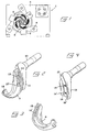
- Reference numeral 1 in Fig. 1 generally designates a barking machine which includes, besides a supporting frame or housing 2, a rotor 3 on which a number of tools 4 according to the invention are mounted.
- the embodiment illustrated comprises five tools, but this number may vary.
- the rotor 3 is annular, and through the hollow space 5 thereof a log 6 can be fed lengthwise by means of a suitable number of rotating rolls 7, for example three rolls which preferably are in the form of jagged rolls pivotally mounted in journals 8. It is pointed out that the jagged rolls 7 are distinctly separate from the rotor 3 in a direction perpendicular to the plane of the drawing so that the rolls will not come into contact with the rotor. It is also pointed out that a corresponding set of feed rolls are mounted on the rear side of the housing 2, such that a log can be fed before a log end has entered into contact with the tools, or discharged after a log end has lost contact with the tools.
- the tool illustrated in Figs. 2-6 comprises the actual swinging arm 9 and a shaft 10 which is journaled in the rotor 3 and which at its end protruding from the rotor has a holder 11.
- the holder 11 preferably is formed in one piece with the shaft 10, but may also be designed as a separate part which subsequently is firmly connected with the shaft 10.
- the swinging arm 9 is curved and has at its free end remote from the holder 11 a seat 12 adapted to accommodate a detachable cutting bit (not shown) which incorporates the cutting edge performing the actual barking operation. Instead of using a separate exchangeable cutting bit, it is also possible to form the cutting edge directly on the swinging arm proper.
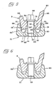
- the swinging arm 9 is detachably connected with the holder 11 via a screw connection which, in the embodiment illustrated, comprises two screws 13, 13' which are in engagement with threaded holes 14, 14' in the holder 11 and extend through oblong holes 15, 15' in the arm 9.
- the holder 11 is formed with two elongated grooves 16, 16' which, in the embodiment illustrated, are curved and spaced apart by an intermediate ridge 17. These grooves are adapted to receive two beads 19, 19' formed on the swinging arm 9 and spaced apart by an intermediate recess 18.
- the two outer lateral faces 20, 20' defining the grooves 16, 16' are sloping in cross-section and converge toward one another in a direction toward the bottoms of the grooves at an angle slightly less than a corresponding angle of convergence between the outer lateral faces 21, 21' defining the beads 19, 19' and extending upwardly along the sides of the swinging arm all the way from the beads to the upper side of the swinging arm.
- the inner lateral faces 22, 22' defining the beads 19, 19' are sloping, but converge upwardly toward the upper side of the swinging arm. These surfaces correspond to similarly sloping and upwardly converging inner lateral faces 23, 23' which together with the outer faces 20, 20' define the grooves 16, 16'.
- the two bead portions 19, 19' of the swinging arm are mutually connected by a relatively thin web portion 24.
- the side of the swinging arm 9 first struck by a log fed into the machine has a flange 25 which is slightly higher than a similar flange 26 on the opposite side of the arm and formed with a relatively sharp edge 27.
- the threaded holes 14, 14' are located in the ridge portion 17 of the holder 11, while the oblong holes 15, 15' through which the screw shanks extend, are positioned in the web portion 24 of the swinging arm.
- the screw heads 28 may conveniently be in the form of square heads which are not notably higher than the lowest lateral flange 26 of the swinging arm, whereby the heads are accommodated by the protected space between the flanges 25 and 26.
- the grooves 16 are formed in the holder 11 and the beads 19 in the swinging arm 19.
- the reverse is also possible, i.e. the grooves are formed in the swinging arm and the beads in the holder. The important thing is that the essentially W-shaped cross-sections of the two elements are maintained and made to cooperate in the manner described.
Landscapes
- Engineering & Computer Science (AREA)
- General Engineering & Computer Science (AREA)
- Life Sciences & Earth Sciences (AREA)
- Wood Science & Technology (AREA)
- Forests & Forestry (AREA)
- Mechanical Engineering (AREA)
- Earth Drilling (AREA)
- Harvester Elements (AREA)
- Gripping On Spindles (AREA)
- Details Of Spanners, Wrenches, And Screw Drivers And Accessories (AREA)
- Finish Polishing, Edge Sharpening, And Grinding By Specific Grinding Devices (AREA)
- Orthopedics, Nursing, And Contraception (AREA)
- Measuring Pulse, Heart Rate, Blood Pressure Or Blood Flow (AREA)
- Debarking, Splitting, And Disintegration Of Timber (AREA)
Claims (3)
- Outil pour machine d'écorçage du type annulaire rotatif, comprenant un arbre (10) monté à rotation dans un rotor (3) d'une telle machine, un porte-outil (11) associé audit arbre et s'étendant angulairement par rapport à celui-ci, et un bras pivotant courbé (9) qui est destiné à porter une arête de coupe à une première extrémité libre et qui est relié, à l'extrémité opposée, de façon amovible au porte-outil (11) par un assemblage par vis (13, 13'), caractérisé en ce que le porte-outil (11), ou bien le bras pivotant (9), présente deux rainures allongées (16, 16') qui sont espacées par une nervure intermédiaire (17) et destinées à recevoir deux nervures (19, 19') qui sont prévues sur le bras pivotant (9), ou bien sur le porte-outil (11), et espacées par un évidement intermédiaire (18), chaque rainure (16, 16') étant définie par des faces latérales intérieures (23, 23') et extérieures (20, 20'), et chaque nervure (19, 19') étant définie par des faces intérieures (22, 22') et extérieures (21, 21'); en ce que les deux faces latérales extérieures (20, 20') des rainures (16, 16') sont inclinées en section droite de façon convergente vers le fond des rainures d'un angle légèrement inférieur à un angle de convergence correspondant des faces latérales extérieures (21, 21') des nervures (19, 19'); en ce que les faces latérales intérieures (22, 22') des nervures (19, 19') ainsi que les faces latérales intérieures (23, 23') des rainures (16, 16') sont inclinées elles aussi, les faces latérales intérieures et extérieures (22, 21; 22', 21') de chaque nervure (19, 19') convergeant vers le fond de rainure y associé; et en ce que l'extrémité de chaque nervure (19, 19') faisant face à une rainure y associée est plus large que le fond de rainure, les nervures (19, 19') étant forcées, lors du serrage de l'assemblage par vis (13, 13'), dans les deux rainures (16, 16') de façon que la différence entre lesdits angles de convergence soit réduite par degrés vers zéro par déformation élastique jusqu'à ce que les faces latérales intérieures (22, 22') des nervures (19, 19') viennent en contact avec les faces latérales intérieures (23, 23') des rainures (16, 16'), l'assemblage par vis étant alors suffisamment serré.
- Outil selon la revendication 1, caractérisé en ce qu'une vis faisant partie de l'assemblage par vis (13, 13') s'étend librement à travers un premier trou (15, 15') pratiqué dans une âme relativement mince (24) reliant les deux nervures (19, 19') et s'engage dans un second trou taraudé (14, 14') pratiqué dans la nervure intermédiaire (17) séparant entre les deux rainures (16, 16').
- Outil selon les revendications 1 et 2, caractérisé en ce que les deux rainures (16, 16') et les deux nervures (19, 19') sont courbées circulairement; et en ce que le premier trou (15, 15') est allongé et courbé circulairement, le bras pivotant (9) pouvant se déplacer par rapport au porte-outil (11) et être fixé au moyen de l'assemblage par vis (13, 13') dans des positions différentes choisies par rapport à ce dernier afin de permettre de régler la distance entre le centre de l'arbre rotatif et le centre de masse du bras pivotant.
Priority Applications (1)
| Application Number | Priority Date | Filing Date | Title |
|---|---|---|---|
| AT89850175T ATE94798T1 (de) | 1988-06-08 | 1989-05-30 | Werkzeug fuer entrindungsmaschinen mit einem rotierenden ring. |
Applications Claiming Priority (2)
| Application Number | Priority Date | Filing Date | Title |
|---|---|---|---|
| SE8802141A SE463662B (sv) | 1988-06-08 | 1988-06-08 | Verktyg foer barkningsmaskiner av haalrotortyp |
| SE8802141 | 1988-06-08 |
Publications (3)
| Publication Number | Publication Date |
|---|---|
| EP0346309A2 EP0346309A2 (fr) | 1989-12-13 |
| EP0346309A3 EP0346309A3 (fr) | 1991-09-25 |
| EP0346309B1 true EP0346309B1 (fr) | 1993-09-22 |
Family
ID=20372557
Family Applications (1)
| Application Number | Title | Priority Date | Filing Date |
|---|---|---|---|
| EP89850175A Expired - Lifetime EP0346309B1 (fr) | 1988-06-08 | 1989-05-30 | Outil pour machine d'écorçage du type annulaire rotatif |
Country Status (8)
| Country | Link |
|---|---|
| US (1) | US4872495A (fr) |
| EP (1) | EP0346309B1 (fr) |
| AT (1) | ATE94798T1 (fr) |
| CA (1) | CA1316081C (fr) |
| DE (1) | DE68909314T2 (fr) |
| FI (1) | FI84704C (fr) |
| NO (1) | NO170464C (fr) |
| SE (1) | SE463662B (fr) |
Families Citing this family (8)
| Publication number | Priority date | Publication date | Assignee | Title |
|---|---|---|---|---|
| USD315355S (en) | 1988-06-08 | 1991-03-12 | Mecania Ab | Debarking tool |
| USD336905S (en) | 1990-07-13 | 1993-06-29 | Mecania Ab | Swinging arm for a debarking tool |
| SE469117C (sv) * | 1990-12-21 | 1997-12-08 | Soederhamns Verkstaeder Ab | Barkningsverktyg för barkningsmaskiner av hålrotortyp |
| CA2131066C (fr) * | 1994-08-29 | 2001-01-30 | Denis Johnson | Bras et extremites du dispositif d'ecorcage d'une ecorceuse |
| CA2207579A1 (fr) * | 1997-05-28 | 1998-11-28 | Paul Caron | Piece frittee a surface anti-abrasive et procede pour sa realisation |
| USD419854S (en) | 1998-03-13 | 2000-02-01 | Forano International Inc. | Debarker arm |
| USD411097S (en) | 1998-08-05 | 1999-06-15 | Forano International Inc. | Holder for a debarker arm |
| USD903472S1 (en) * | 2019-07-17 | 2020-12-01 | Pmc Industries, Inc. | Top bracket for mounting device |
Family Cites Families (5)
| Publication number | Priority date | Publication date | Assignee | Title |
|---|---|---|---|---|
| US3709272A (en) * | 1971-07-08 | 1973-01-09 | R Bowers | Log debarking apparatus |
| SE415078B (sv) * | 1974-09-25 | 1980-09-08 | Jonsson Karl Erik Arnold | Barkningsverktyg |
| SE430391B (sv) * | 1977-11-11 | 1983-11-14 | Jonsson Karl Erik Arnold | Bearbetningsorgan i barkningsmaskiner av halrotortyp |
| US4438794A (en) * | 1979-07-23 | 1984-03-27 | Carpenter Aaron R | Bark tool and connection |
| US4280541A (en) * | 1980-01-10 | 1981-07-28 | Reimler Associates, Inc. | Debarking tool for log debarking machines |
-
1988
- 1988-06-08 SE SE8802141A patent/SE463662B/sv not_active IP Right Cessation
- 1988-10-26 CA CA000581379A patent/CA1316081C/fr not_active Expired - Lifetime
- 1988-10-27 US US07/263,524 patent/US4872495A/en not_active Expired - Lifetime
-
1989
- 1989-05-30 EP EP89850175A patent/EP0346309B1/fr not_active Expired - Lifetime
- 1989-05-30 AT AT89850175T patent/ATE94798T1/de not_active IP Right Cessation
- 1989-05-30 DE DE89850175T patent/DE68909314T2/de not_active Expired - Fee Related
- 1989-06-07 NO NO892342A patent/NO170464C/no not_active IP Right Cessation
- 1989-06-07 FI FI892800A patent/FI84704C/fi not_active IP Right Cessation
Also Published As
| Publication number | Publication date |
|---|---|
| FI892800L (fi) | 1989-12-09 |
| FI84704B (fi) | 1991-09-30 |
| NO170464B (no) | 1992-07-13 |
| SE8802141D0 (sv) | 1988-06-08 |
| NO170464C (no) | 1992-10-21 |
| EP0346309A3 (fr) | 1991-09-25 |
| US4872495A (en) | 1989-10-10 |
| DE68909314T2 (de) | 1994-04-21 |
| SE463662B (sv) | 1991-01-07 |
| FI892800A0 (fi) | 1989-06-07 |
| FI84704C (fi) | 1992-01-10 |
| NO892342L (no) | 1989-12-11 |
| SE8802141L (sv) | 1989-12-09 |
| NO892342D0 (no) | 1989-06-07 |
| CA1316081C (fr) | 1993-04-13 |
| EP0346309A2 (fr) | 1989-12-13 |
| ATE94798T1 (de) | 1993-10-15 |
| DE68909314D1 (de) | 1993-10-28 |
Similar Documents
| Publication | Publication Date | Title |
|---|---|---|
| US5007685A (en) | Trenching tool assembly with dual indexing capability | |
| EP0502863B1 (fr) | Piece coupante et bloc de montage | |
| EP0830229B1 (fr) | Fraise a grande vitesse de type cartouche | |
| US20030202849A1 (en) | Cutting tool | |
| US6592313B2 (en) | Pull stud bolt | |
| EP0319499B1 (fr) | Machine à écorcer à anneau pour troncs d'arbres | |
| US3940835A (en) | Slotting cutter and cutting insert therefor | |
| EP0346309B1 (fr) | Outil pour machine d'écorçage du type annulaire rotatif | |
| CA2386846A1 (fr) | Fraise et piece de coupe rapportee | |
| JPH04505293A (ja) | 位置調整可能な交換カセットを備えた工具 | |
| KR100259549B1 (ko) | 인덱스가능한 쐐기형 지지부재 및 인서트를 갖는 다중 배향 밀링 커터 | |
| WO1999019104A1 (fr) | Fraise de rainurage | |
| JPH0125642B2 (fr) | ||
| US4744703A (en) | Rotary cutter for slotting or cut-off | |
| JP2606628Y2 (ja) | 無段可変クランプ工具 | |
| US5992199A (en) | Modular knurling tool | |
| EP0008798B1 (fr) | Tête porte-lames pour un rabot à main mû par un moteur | |
| EP0346310B1 (fr) | Outil pour machine d'écorçage du type annulaire rotatif | |
| JP3007291B2 (ja) | 交換可能の工具支持体 | |
| EP1023134A1 (fr) | Fraise de rainurage | |
| CN1187155A (zh) | 卡块式高速铣刀 | |
| JPH0639008B2 (ja) | カツタ−装置 | |
| JPH0512031U (ja) | ヘツド着脱式回転切削工具 | |
| US3830269A (en) | Cutting rotor assembly | |
| US4789018A (en) | Shaper cutterhead assembly with absolutely captive bits |
Legal Events
| Date | Code | Title | Description |
|---|---|---|---|
| PUAI | Public reference made under article 153(3) epc to a published international application that has entered the european phase |
Free format text: ORIGINAL CODE: 0009012 |
|
| AK | Designated contracting states |
Kind code of ref document: A2 Designated state(s): AT DE FR |
|
| PUAL | Search report despatched |
Free format text: ORIGINAL CODE: 0009013 |
|
| AK | Designated contracting states |
Kind code of ref document: A3 Designated state(s): AT DE FR |
|
| 17P | Request for examination filed |
Effective date: 19911206 |
|
| 17Q | First examination report despatched |
Effective date: 19920722 |
|
| GRAA | (expected) grant |
Free format text: ORIGINAL CODE: 0009210 |
|
| AK | Designated contracting states |
Kind code of ref document: B1 Designated state(s): AT DE FR |
|
| PG25 | Lapsed in a contracting state [announced via postgrant information from national office to epo] |
Ref country code: FR Effective date: 19930922 |
|
| REF | Corresponds to: |
Ref document number: 94798 Country of ref document: AT Date of ref document: 19931015 Kind code of ref document: T |
|
| REF | Corresponds to: |
Ref document number: 68909314 Country of ref document: DE Date of ref document: 19931028 |
|
| EN | Fr: translation not filed | ||
| PLBE | No opposition filed within time limit |
Free format text: ORIGINAL CODE: 0009261 |
|
| STAA | Information on the status of an ep patent application or granted ep patent |
Free format text: STATUS: NO OPPOSITION FILED WITHIN TIME LIMIT |
|
| 26N | No opposition filed | ||
| PGFP | Annual fee paid to national office [announced via postgrant information from national office to epo] |
Ref country code: AT Payment date: 20040521 Year of fee payment: 16 |
|
| PGFP | Annual fee paid to national office [announced via postgrant information from national office to epo] |
Ref country code: DE Payment date: 20040727 Year of fee payment: 16 |
|
| PG25 | Lapsed in a contracting state [announced via postgrant information from national office to epo] |
Ref country code: AT Free format text: LAPSE BECAUSE OF NON-PAYMENT OF DUE FEES Effective date: 20050530 |
|
| PG25 | Lapsed in a contracting state [announced via postgrant information from national office to epo] |
Ref country code: DE Free format text: LAPSE BECAUSE OF NON-PAYMENT OF DUE FEES Effective date: 20051201 |