EP0346080B1 - Luftkasten mit drei Teilströmen - Google Patents
Luftkasten mit drei Teilströmen Download PDFInfo
- Publication number
- EP0346080B1 EP0346080B1 EP89305718A EP89305718A EP0346080B1 EP 0346080 B1 EP0346080 B1 EP 0346080B1 EP 89305718 A EP89305718 A EP 89305718A EP 89305718 A EP89305718 A EP 89305718A EP 0346080 B1 EP0346080 B1 EP 0346080B1
- Authority
- EP
- European Patent Office
- Prior art keywords
- air
- bar
- chamber
- slots
- bar according
- Prior art date
- Legal status (The legal status is an assumption and is not a legal conclusion. Google has not performed a legal analysis and makes no representation as to the accuracy of the status listed.)
- Expired - Lifetime
Links
- 238000005188 flotation Methods 0.000 title claims description 46
- 238000001035 drying Methods 0.000 claims description 8
- 230000000694 effects Effects 0.000 claims description 5
- 230000015556 catabolic process Effects 0.000 description 1
- 238000006731 degradation reaction Methods 0.000 description 1
- 230000001627 detrimental effect Effects 0.000 description 1
- 238000004513 sizing Methods 0.000 description 1
- 230000000087 stabilizing effect Effects 0.000 description 1
Images


Classifications
-
- F—MECHANICAL ENGINEERING; LIGHTING; HEATING; WEAPONS; BLASTING
- F26—DRYING
- F26B—DRYING SOLID MATERIALS OR OBJECTS BY REMOVING LIQUID THEREFROM
- F26B13/00—Machines and apparatus for drying fabrics, fibres, yarns, or other materials in long lengths, with progressive movement
- F26B13/10—Arrangements for feeding, heating or supporting materials; Controlling movement, tension or position of materials
- F26B13/101—Supporting materials without tension, e.g. on or between foraminous belts
- F26B13/104—Supporting materials without tension, e.g. on or between foraminous belts supported by fluid jets only; Fluid blowing arrangements for flotation dryers, e.g. coanda nozzles
-
- B—PERFORMING OPERATIONS; TRANSPORTING
- B65—CONVEYING; PACKING; STORING; HANDLING THIN OR FILAMENTARY MATERIAL
- B65H—HANDLING THIN OR FILAMENTARY MATERIAL, e.g. SHEETS, WEBS, CABLES
- B65H23/00—Registering, tensioning, smoothing or guiding webs
- B65H23/04—Registering, tensioning, smoothing or guiding webs longitudinally
- B65H23/24—Registering, tensioning, smoothing or guiding webs longitudinally by fluid action, e.g. to retard the running web
-
- B—PERFORMING OPERATIONS; TRANSPORTING
- B65—CONVEYING; PACKING; STORING; HANDLING THIN OR FILAMENTARY MATERIAL
- B65H—HANDLING THIN OR FILAMENTARY MATERIAL, e.g. SHEETS, WEBS, CABLES
- B65H2406/00—Means using fluid
- B65H2406/10—Means using fluid made only for exhausting gaseous medium
- B65H2406/11—Means using fluid made only for exhausting gaseous medium producing fluidised bed
- B65H2406/112—Means using fluid made only for exhausting gaseous medium producing fluidised bed for handling material along preferably rectilinear path, e.g. nozzle bed for web
Definitions
- the present invention relates to an air flotation bar for use in positioning, drying or curing of a continuous planar flexible material such as a printed web, news print, film material or sheet plastic.
- the present invention more particularly pertains to an air flotation bar which includes two individual air bars in the upper region of the air flotation bar, each having an air discharge slot about its longitudinal outer edge and a third air discharge slot between the two air bars.
- the outer slots provide for web flotation and heat transfer, and the third slot between the outer air bars provides for additional heat transfer air flow and flotation by air impinging upon the web.
- the present invention overcomes the disadvantages of the prior art by providing an air flotation bar where the same flotation capability is maintained, as well as enhanced heat transfer.
- Three small air slots instead of two larger air slots provide for an equal air flow orifice area in addition to a substantially equal distributed air flow.
- GB-A-1302091 discloses an air bar structure having two Coanda slots along the edges of the air bar, directing airflows in towards the centre of the air bar, and the embodiment of Figures 8 to 15 disclosed therein includes third air discharge means in the form of slots or holes which extend along the top plate of the air bar and are described as being intended to peel the Coanda airstream from the Coanda surface along the top of the air bar.
- the air leaving the additional air discharge means is illustrated in Figures 8 to 10 as moving perpendicular to the Coanda surface at the top of the air bar.
- an air flotation bar comprising: an air bar header; first and second substantially parallel, longitudinal air discharge Coanda slots positioned on the margins of a top surface of said air bar header; a third longitudinal air discharge slot between and parallel to said first and second longitudinal air discharge Coanda slots and on said top surface; chamber means in said air bar header for passing air to each of said air discharge slots; and air supply means operative to supply air to said chamber means; characterised in that in use of said air flotation bar the air flow from said third slot exhibits the Coanda effect; and in that there is at least one central longitudinal suction hole between said third longitudinal discharge slot and each of said first and second longitudinal discharge slots.
- an air flotation bar with longitudinal parallel mounted air bars mounted about the upper regions of an air bar header.
- the first and second air discharge slots which use the Coanda effect, are formed along the outer longitudinal edges of each air bar and the third air discharge slot is formed between the inner longitudinal edges of the air bars.
- a support channel member is placed longitudinally across the greater portion in the upper region of the air flotation bar to support the inner ends of the air bars.
- Individual chambers with perforated elements direct pressurized air from the intermediate regions of the air flotation bar to each of the air discharge slots.
- Another larger chamber with perforations in the intermediate region and beneath each of the individual chambers uniformly channels pressurized air to each of the smaller individual chambers.
- Another chamber in the lower region in turn delivers air to the chamber in the intermediate region.
- a significant feature of the present invention is the ability to increase the size of the air flotation bar and maintain the same flotation capability without loss of the heat transfer coefficient.
- a further significant feature of the present invention is the use of three smaller sized air slots instead of two normal sized slots, providing for a more widely distributed uniform drying air flow with enhanced heat transfer.
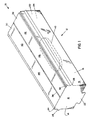
- FIG. 1 illustrates a perspective view of an air flotation bar 10 for use in a web dryer.
- Externally visible members in the figure illustrate the air flotation bar 10 including a channel like air bar header 12 with opposing canted sides 14 and 15, and a bottom 16.
- Opposing and parallel vertically aligned air bar header end plates 18 and 20 affix between the sides 14 and 15 with each end plate having an air bar alignment tab 22 and 24, as also illustrated in FIG. 4. Holes, slots or other various openings can be fabricated in the air bar alignment tabs 22 and 24 for securing, mounting or positioning of the air flotation bar 10 in a dryer.
- V channels 26 and 28 are formed in and aligned horizontally in sides 15 and 14, respectively, to accommodate air bar mounting flanges, as later described in detail.
- Air bars 30 and 32 align longitudinally in a precise manner between the upper regions of sides 14 and 15 longitudinally to form aligned Coanda slots 34, 36, and 38 as illustrated.
- Two outer air discharge slots, in this case Coanda slots, 34 and 38 position as illustrated with an inner third slot 36, also using the Coanda effect, between air bars 30 and 32.
- An oval shaped air inlet 40 positions on the bottom 16 to accept dryer system air flow for the air flotation bar 10.
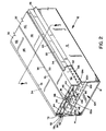
- FIG. 2 illustrates a partial cutaway view of the air flotation bar 10 with the air bar header end plate removed for purposes of the illustration. All numerals correspond to those elements previously described. Reference to this FIG. and FIG. 3 also facilitates an understanding of the following disclosed subject matter.
- Air bars 30 and 32 are mirror images of each other, and position between the upper regions of sides 14 and 15. Air bar 32 includes an upper air bar channel member 42 and a lower air bar channel member 44 tightly secured and affixed within the upper air bar channel member 42 forming an air bar chamber.
- the upper air bar channel member 42 includes a horizontal planar surface 46, which intersects an inner vertical surface 48 to form a uniform defined radius Coanda curve 50, and also intersects an outer vertical surface 52 to form a uniform defined radius Coanda curve 54.
- the outer vertical surface 52 is bent at a right angle to form a horizontally aligned flange member 56 which in turn is accommodated by the V channel 26.
- the flange member 56 includes a plurality of holes 58a-58n where hole 58a and other like holes in the series are illustrated in the figure.
- a lip 60a of a sidewall 60 extends a finite distance inwardly at a right angle from the upper region of side 15 and on a plane lower than that of the horizontal planar surface 46 of the air bar 32 to form a Coanda slot 38 of a finite distance between the lip 60a and Coanda curve 54.
- An outer chamber 62 is also formed by the flange member 56, the upper portion of side 15, the outer vertical surface 52 and lip 60a.
- Air bar 30 is constructed in a like and similar manner to that of air bar 32, and includes a horizontal planar surface 66, an inner vertical surface 68, a Coanda curve 70, an outer vertical surface 72, a Coanda curve 74, a flange member 76, holes 78a-78n where only hole 78a and the other like holes in the series are illustrated, a lip 80a of sidewall 80 and an outer chamber 82.
- a support channel member 90 positions between the outer vertical surface 52 and outer vertical surface 72, and includes a plurality of orifices 92a-92n where only orifice 92a is illustrated.
- Vertically oriented struts 94 and 96 are positioned perpendicular on the support channel member 90 to support the inner ends of air bars 30 and 32, thus stabilizing the geometrical configuration of the inner Coanda slot 36 and forming outer support chambers 62 and 82.
- a central support chamber 91 is formed by struts 94 and 96, the support channel member 90, and the lower portions of the air bar channel members 44 and 64.
- a diffuser plate 100 including a plurality of holes 102a-102n secured between sides 14 and 15, and below the support channel member 90, provides for even flow of drying air from the oval shaped air inlet 40 of FIGS. 1 and 3.
- the diffuser plate 100, sides 14 and 15, air bar header end plates 18 and 20 of FIG. 1, and the bottom 16 define a first lower air flow chamber 104.
- the portions of the sides 14 and 15 just below the V channels 26 and 28, air bar header end plates 18 and 20, the support channel member 90 and the flange members 56 and 76 define a second upper diffused air flow chamber 106.
- An angled oval member 108 secures to the bottom 16 and adjacent to and about the oval shaped air inlet 40 to form a gasket chamber 111 about the oval shaped air inlet 40 as illustrated in FIG. 3.
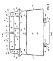
- FIG. 3 illustrates a cross-sectional view of the present invention taken along line 3-3 of FIG. 2 where all numerals correspond to those elements previously described.
- FIG. 4 illustrates a partial front view and partial cutaway view taken along line 4-4 of FIG. 3 of the air flotation bar where all numerals correspond to those elements previously described.
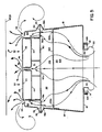
- FIG. 5 illustrates a view of FIG. 3 with air flow in and about the air flotation bar 10 where all numerals correspond to those elements previously described.
- Dryer system air flows first through the oval shaped air inlet 40 and out of the Coanda slots 34, 36 and 38 as previously described. Air passing through the Coanda slots 34, 36, and 38, forms a broad air flow area to support a web. Air passing through the Coanda slot 36 projects and moves upwardly to, in effect, widen the distance between the flow of air flowing along towards the web and to provide a wider upper flow area beneath the web.
- the drying air flow has a wider foot print to provide a larger more effective drying area with heat transfer on the web.
- Dryer system air flow passes first through the oval shaped air inlet 40 of FIG. 3, through the first lower air flow chamber 104, through the diffuser plate 100 where the air flow is distributed evenly and diffused through the second upper diffused air flow chamber 106, and simultaneously through a plurality of holes 58a-58n, 78a-78n, and 92a-92n into chambers 62, 82, and 91, respectively.
- the diffuser plate straightens the air flow. Any other like structure which creates a pressure drop would act as a flow straightener.
- the air flow then continues from chambers 62, 82, and 91, and through Coanda slots 38, 34 and 36.
- each slot is about 0.035-0.2 ⁇ by way of example and for purposes of illustration and not to be construed as limiting of the present invention, and in a range of preferably about 1.3-1.9% open area of the plane.
- the open area of the slots is in a range of 1-5% of the open area of the plane.
- FIG. 6 illustrates an alternative embodiment of the air flotation bar where all numerals correspond to those elements previously described. Negative pressure is applied to the interior chambers 110 and 112 of air bars 30 and 32 to create an area of low pressure in the areas of longitudinal holes 114 and 116, thus affecting air flow from the outer and inner Coanda slots 34 and 38, and 36, respectively, in the manner as illustrated by the air flow arrows.
- the air flotation bar can be used for drying of printed webs, coated webs, or any other suitable air flotation applications.
Landscapes
- Engineering & Computer Science (AREA)
- Textile Engineering (AREA)
- Mechanical Engineering (AREA)
- General Engineering & Computer Science (AREA)
- Drying Of Solid Materials (AREA)
- Supply, Installation And Extraction Of Printed Sheets Or Plates (AREA)
- Duct Arrangements (AREA)
Claims (14)
- Luftströmungskasten mit: einem Luftkasten-Kopfstück (12); ersten und zweiten im wesentlichen parallelen, längsgerichteten Luftauslaß-Coanda-Schlitzen (34, 38), die an den Rändern einer Oberseite des Luftkasten-Kopfstücks angeordnet sind; einem dritten längsgerichteten Luftauslaßschlitz (36) zwischen und parallel den ersten und zweiten längsgerichteten Luftauslaß-Coanda-Schlitzen und auf der Oberseite; Kammereinrichtungen (104, 106) in dem Luftkasten-Kopfstück zum Leiten von Luft zu jedem der Luftauslaßschlitze; und Luftzufuhreinrichtungen, die wirksam sind, um Luft zu den Kammereinrichtungen zu liefern; dadurch gekennzeichnet, daß beim Gebrauch des Luftströmungskastens der Luftstrom von dem dritten Schlitz den Coanda-Effekt zeigt; und daß wenigstens ein zentrales, längsgerichtetes Saugloch (114, 116) zwischen dem dritten längsgerichteten Auslaßschlitz und jedem der ersten und zweiten längsgerichteten Auslaßschlitze vorgesehen ist.
- Luftströmungskasten nach Anspruch 1, wobei die Kammereinrichtungen aufweisen: eine Hauptkammer (104, 106); eine zentrale Hilfskammer (91) und zwei seitliche Hilfskammern (62, 82) zu jeder Seite der zentralen Hilfskammer, wobei die zentrale Hilfskammer mit der Hauptkammer (104, 106) verbunden ist; obere Luftkasten-Kanalkammern (44, 64), die dazwischen den dritten Luftauslaßschlitz oberhalb der zentralen Hilfskammer bilden; und Seitenwände (60, 80) mit Lippen (60a, 80a), die um die Hilfskammern und Außenseiten der oberen Luftkasten-Kanalkammern angeordnet sind, dazu beabstandet sind und die ersten und zweiten Lüftauslaß-CoandaSchlitze (34, 38) bilden.
- Luftströmungskasten nach Anspruch 2, der eine Diffuserplatte (100) mit Löchern (102a ... 102n) darin aufweist, die auf halbem Wege nach oben in der Kammer (104, 106) befestigt ist.
- Luftströmungskasten nach Anspruch 2, der Strömungsbegradigungseinrichtungen (100; 102a ... 102n) in der Kammer aufweist.
- Luftströmungskasten nach Anspruch 4, wobei die Kammereinrichtungen ferner aufweisen: eine untere Luftströmungskammer (104) und eine obere Luftströmungskammer (106), wobei die Strömungsbegradigungseinrichtungen dazwischen angeordnet sind.
- Luftströmungskasten nach Anspruch 2, der Einrichtungen (100; 102a ... 102n) zum Erzeugen eines Druckabfalls in der Hauptkammer aufweist.
- Luftströmungskasten nach einem der Ansprüche 2 bis 6, wobei die Kammereinrichtungen ferner aufweisen: ein Bodenelement (16) mit einem Einlaßloch (40) darin, an dem Bodenelement (16) angebrachte Luftkasten-Kopfstück-Endplatten (18, 20), zwei sich von dem Bodenelement nach oben erstreckende Seiten (14, 15); an den Seitenelementen befestigte, sich gegenüberliegende, rechtwinklige Flanschelemente (56, 76), wobei jedes Flanschelement in einer Basis davon Löcher (58a ... 58n) aufweist, wobei ein oberer Rand (54) jedes der Flanschelemente und ein oberer Rand (60a, 80a) des benachbarten Seitenelements (15, 14) den ersten bzw. zweiten Coanda-Schlitz (38, 34) um jedes Seitenelement bilden; ein Halteelement (90) mit Zentralöffnungen (92a ... 92n), die sich zwischen den Flanschelementen erstrecken; sich gegenüberliegende vertikale Versteifungen (94, 96), die um jede Seite der Öffnungen befestigt sind; sich gegenüberliegende untere und obere Luftkastenkanäle, die zwischen dem Flanschelement und den Versteifungen befestigt sind und dazwischen den dritten Coanda-Schlitz bilden.
- Luftströmungskasten nach einem der Ansprüche 2 bis 7, wobei die Ecken der oberen Luftkastenkanalelemente gekrümmt sind.
- Luftströmungskasten nach einem der Ansprüche 1 bis 8, wobei alle Luftauslaßschlitze (34, 36, 38) (204, 206, 208) in der Breite im wesentlichen gleich sind.
- Luftströmungskasten nach einem der Ansprüche 1 bis 9, wobei jeder der Luftauslaßschlitze (34, 36, 38) (204, 206, 208) 2,54 mm (0,1˝) breit ist.
- Luftströmungskasten nach einem der Ansprüche 1 bis 10, wobei die offene Fläche der Luftauslaßschlitze 1 bis 5% der Fläche des Luftkastens (10) (150) beträgt.
- Luftströmungskasten nach Anspruch 11, wobei die offene Fläche jedes der Schlitze 1,3 bis 1,9% der Fläche des Luftkastens beträgt.
- Verwendung eines Luftströmungskastens nach einem der Ansprüche 1 bis 12 zum Trocknen eines gedruckten Bandes.
- Verwendung eines Luftströmungskastens nach einem der Ansprüche 1 bis 12 zum Trocknen eines beschichteten Bandes.
Applications Claiming Priority (2)
| Application Number | Priority Date | Filing Date | Title |
|---|---|---|---|
| US203072 | 1988-06-07 | ||
| US07/203,072 US4901449A (en) | 1988-06-07 | 1988-06-07 | Tri-flotation air bar |
Publications (2)
| Publication Number | Publication Date |
|---|---|
| EP0346080A1 EP0346080A1 (de) | 1989-12-13 |
| EP0346080B1 true EP0346080B1 (de) | 1995-04-19 |
Family
ID=22752373
Family Applications (1)
| Application Number | Title | Priority Date | Filing Date |
|---|---|---|---|
| EP89305718A Expired - Lifetime EP0346080B1 (de) | 1988-06-07 | 1989-06-07 | Luftkasten mit drei Teilströmen |
Country Status (5)
| Country | Link |
|---|---|
| US (1) | US4901449A (de) |
| EP (1) | EP0346080B1 (de) |
| JP (1) | JPH0722992B2 (de) |
| CA (1) | CA1337452C (de) |
| DE (1) | DE68922245T2 (de) |
Families Citing this family (24)
| Publication number | Priority date | Publication date | Assignee | Title |
|---|---|---|---|---|
| CH679931A5 (de) * | 1990-04-18 | 1992-05-15 | Brandwijk Systems Programming | |
| US5064979A (en) * | 1990-08-07 | 1991-11-12 | W. R. Grace & Co.-Conn. | Microwave air float bar for drying a traveling web |
| US5105562A (en) * | 1990-12-26 | 1992-04-21 | Advance Systems, Inc. | Web dryer apparatus having ventilating and impingement air bar assemblies |
| US5150955A (en) * | 1990-12-28 | 1992-09-29 | Eastman Kodak Company | Drying apparatus |
| US5181329A (en) * | 1990-12-28 | 1993-01-26 | Eastman Kodak Company | Drying apparatus |
| DE4127602A1 (de) * | 1991-08-21 | 1993-02-25 | Hoechst Ag | Verfahren und vorrichtung zum beruehrungsfreien fuehren eines beschichteten materialbandes |
| US6293196B1 (en) * | 1993-10-06 | 2001-09-25 | Howard W. DeMoore | High velocity, hot air dryer and extractor |
| US5590480A (en) * | 1994-12-06 | 1997-01-07 | W. R. Grace & Co.-Conn. | combination air bar and hole bar flotation dryer |
| DE19607397A1 (de) * | 1996-02-28 | 1997-09-04 | Heidelberger Druckmasch Ag | Vorrichtung und Verfahren zur Führung von bogenförmigem Material in einer Druckmaschine, insbesondere in einer Bogenrotations-Offsetdruckmaschine |
| WO1997046619A1 (fr) * | 1996-06-05 | 1997-12-11 | Elf Atochem S.A. | Compositions de resines thermoplastiques multiphases |
| FR2790072B1 (fr) * | 1999-02-18 | 2001-05-25 | Solaronics Process | Dispositif combine de soufflage et d'aspiration a echange energetique integre pour un dispositif de sechage |
| US7530179B2 (en) * | 2004-04-13 | 2009-05-12 | Megtec Systems, Inc. | Step air foil |
| US7311234B2 (en) * | 2005-06-06 | 2007-12-25 | The Procter & Gamble Company | Vectored air web handling apparatus |
| US7694433B2 (en) | 2005-06-08 | 2010-04-13 | The Procter & Gamble Company | Web handling apparatus and process for providing steam to a web material |
| DE102005054995B4 (de) * | 2005-07-28 | 2014-03-13 | Otto Junker Gmbh | Düsensystem für die Behandlung von bahnförmigem Gut |
| US8061055B2 (en) * | 2007-05-07 | 2011-11-22 | Megtec Systems, Inc. | Step air foil web stabilizer |
| US8615899B2 (en) | 2008-08-27 | 2013-12-31 | Megtec Systems, Inc. | Paired air bar/hole bar arrangement in web dryer |
| JP5294777B2 (ja) * | 2008-09-24 | 2013-09-18 | ヤマザキマザック株式会社 | 工作機械のミル主軸 |
| US8083896B2 (en) * | 2008-09-26 | 2011-12-27 | Honeywell Asca Inc. | Pressure equalizing baffle and coanda air clamp |
| EP2942196B8 (de) | 2009-06-05 | 2018-01-10 | Babcock & Wilcox MEGTEC, LLC | Verbesserter infrarot-schwimmbalken |
| FR3030584B1 (fr) * | 2014-12-17 | 2019-05-10 | Andritz Perfojet Sas | Installation d'extraction d'eau |
| US10598433B2 (en) | 2015-04-10 | 2020-03-24 | Durr Systems, Inc. | Remote nozzle deckle system |
| KR20200098115A (ko) * | 2019-02-12 | 2020-08-20 | 삼성전자주식회사 | 건조기 |
| JP7523294B2 (ja) * | 2020-09-18 | 2024-07-26 | 株式会社Screenホールディングス | 気体供給ノズル及びそれを備えた乾燥ユニット並びにインクジェット印刷装置 |
Citations (1)
| Publication number | Priority date | Publication date | Assignee | Title |
|---|---|---|---|---|
| EP0003414A2 (de) * | 1978-01-27 | 1979-08-08 | Spooner Edmeston Engineering Limited | Vorrichtung zu einer schwebenden Behandlung |
Family Cites Families (21)
| Publication number | Priority date | Publication date | Assignee | Title |
|---|---|---|---|---|
| CA768851A (en) * | 1967-10-10 | Kalle Aktiengesellschaft | Treatment of material in web form | |
| US2492974A (en) * | 1946-04-30 | 1950-01-03 | Dungler Julien | Nozzle member used for the drying of textile and other materials |
| US3198499A (en) * | 1961-08-11 | 1965-08-03 | Kaiser Aluminium Chem Corp | Method and apparatus for supporting and heat treating |
| US3549070A (en) * | 1969-02-27 | 1970-12-22 | Tec Systems | Floatation of sheet materials |
| US3672066A (en) * | 1970-10-30 | 1972-06-27 | Bechtel Int Corp | Microwave drying apparatus |
| US3827639A (en) * | 1972-01-04 | 1974-08-06 | J Relue | Drying chamber apparatus |
| US3873013A (en) * | 1973-10-04 | 1975-03-25 | Tec Systems | High velocity web floating air bar having center exhaust means |
| US3982327A (en) * | 1975-05-01 | 1976-09-28 | Midland-Ross Corporation | Air-dispensing web-floating apparatus |
| NO141469L (de) * | 1975-12-09 | |||
| US4292745A (en) * | 1978-08-29 | 1981-10-06 | Caratsch Hans Peter | Air foil nozzle dryer |
| FI57142C (fi) * | 1978-09-11 | 1980-06-10 | Valmet Oy | Munstycke foer behandling av materialbanor |
| US4197971A (en) * | 1978-10-12 | 1980-04-15 | W. R. Grace & Co. | High velocity web floating air bar having an internal passage for transverse air discharge slot means |
| US4197973A (en) * | 1978-10-12 | 1980-04-15 | W. R. Grace & Co. | High velocity web floating air bar having air flow straightening means for air discharge slot means |
| US4201323A (en) * | 1978-10-12 | 1980-05-06 | W. R. Grace & Co. | High velocity web floating air bar having a recessed Coanda plate |
| GB2058313A (en) * | 1979-08-24 | 1981-04-08 | Caratsch Hans Peter | Air foil nozzle dryer |
| US4265384A (en) * | 1980-01-21 | 1981-05-05 | W. R. Grace & Co. | Air bar having asymmetrical inlet |
| US4425719A (en) * | 1982-03-15 | 1984-01-17 | W. R. Grace & Co. | Compact air bar assembly for contactless web support |
| US4472888A (en) * | 1982-06-04 | 1984-09-25 | Cary Metal Products, Inc. | Coanda effect nozzle for handling continuous webs |
| GB2126974B (en) * | 1982-09-07 | 1985-09-11 | Grace W R & Co | Device for supporting a web on a bed of air |
| GB2146303B (en) * | 1983-08-20 | 1987-01-14 | Spooner Ind Ltd | Device for supporting web on a bed of air |
| US4768695A (en) * | 1987-06-11 | 1988-09-06 | Advance Systems, Inc. | Air bar for paper web handling apparatus and having an air distributing chamber and perforated plate therefor |
-
1988
- 1988-06-07 US US07/203,072 patent/US4901449A/en not_active Expired - Lifetime
-
1989
- 1989-06-06 CA CA000601907A patent/CA1337452C/en not_active Expired - Fee Related
- 1989-06-07 DE DE68922245T patent/DE68922245T2/de not_active Expired - Fee Related
- 1989-06-07 JP JP1145047A patent/JPH0722992B2/ja not_active Expired - Fee Related
- 1989-06-07 EP EP89305718A patent/EP0346080B1/de not_active Expired - Lifetime
Patent Citations (1)
| Publication number | Priority date | Publication date | Assignee | Title |
|---|---|---|---|---|
| EP0003414A2 (de) * | 1978-01-27 | 1979-08-08 | Spooner Edmeston Engineering Limited | Vorrichtung zu einer schwebenden Behandlung |
Also Published As
| Publication number | Publication date |
|---|---|
| EP0346080A1 (de) | 1989-12-13 |
| JPH0225334A (ja) | 1990-01-26 |
| US4901449A (en) | 1990-02-20 |
| CA1337452C (en) | 1995-10-31 |
| JPH0722992B2 (ja) | 1995-03-15 |
| DE68922245T2 (de) | 1995-11-09 |
| DE68922245D1 (de) | 1995-05-24 |
Similar Documents
| Publication | Publication Date | Title |
|---|---|---|
| EP0346080B1 (de) | Luftkasten mit drei Teilströmen | |
| MY109767A (en) | Moulded baffle heat exchanger | |
| US4785986A (en) | Paper web handling apparatus having improved air bar with dimensional optimization | |
| US4197973A (en) | High velocity web floating air bar having air flow straightening means for air discharge slot means | |
| FI106268B (fi) | Menetelmä ja laite jatkuvan ainerainan käsittelemiseksi | |
| FI73820C (fi) | Anordning foer vaermebehandling av flata, banformiga materialbanor. | |
| EP0096532A2 (de) | Düsenkasten mit Coanda-Effekt zur Behandlung von fortlaufenden Bahnen | |
| US4069595A (en) | Arrangement for conveying web material through a treating plant | |
| KR920011727A (ko) | 시이트 공급식 윤전 인쇄기용 진공 트랜스퍼 장치 | |
| EP0796415B1 (de) | Schwebetrockner mit kombinationsluftblas-luftlochkasten | |
| EP0568301B1 (de) | Luftführungsvorrichtung mit einer Ablaufplatte zum Wenden einer bewegten Bahn | |
| GB2025020A (en) | Air dryer nozzle | |
| US3800438A (en) | Apparatus for treatment of materials, particularly the heat treatment of webs | |
| US3599341A (en) | Method and apparatus for drying a web | |
| CA1240504A (en) | Device for drying and guiding a web | |
| JP4782773B2 (ja) | エアフォイル及びこれを備えたウェブ乾燥機 | |
| JPS63311079A (ja) | ウエブ乾燥装置 | |
| US3589022A (en) | Air ventilating and circulating system for microwave dryers | |
| US4768695A (en) | Air bar for paper web handling apparatus and having an air distributing chamber and perforated plate therefor | |
| JPS57196077A (en) | Device for simultaneously hot air-drying and supporting continuous web | |
| JP3703803B2 (ja) | 加工機械内でウェブ材料または枚葉紙材料を浮遊させながらガイドするための装置 | |
| EP0346081B1 (de) | Blaskasten für Luftkissen | |
| US6170819B1 (en) | Non-contact sheet handling system and method of using same | |
| US5125170A (en) | Flotation dryer nozzle | |
| FI54955C (fi) | Baerytetorkare. |
Legal Events
| Date | Code | Title | Description |
|---|---|---|---|
| PUAI | Public reference made under article 153(3) epc to a published international application that has entered the european phase |
Free format text: ORIGINAL CODE: 0009012 |
|
| AK | Designated contracting states |
Kind code of ref document: A1 Designated state(s): DE FR GB IT |
|
| 17P | Request for examination filed |
Effective date: 19900321 |
|
| 17Q | First examination report despatched |
Effective date: 19910430 |
|
| GRAA | (expected) grant |
Free format text: ORIGINAL CODE: 0009210 |
|
| AK | Designated contracting states |
Kind code of ref document: B1 Designated state(s): DE FR GB IT |
|
| REF | Corresponds to: |
Ref document number: 68922245 Country of ref document: DE Date of ref document: 19950524 |
|
| ITF | It: translation for a ep patent filed | ||
| ET | Fr: translation filed | ||
| PLBE | No opposition filed within time limit |
Free format text: ORIGINAL CODE: 0009261 |
|
| STAA | Information on the status of an ep patent application or granted ep patent |
Free format text: STATUS: NO OPPOSITION FILED WITHIN TIME LIMIT |
|
| 26N | No opposition filed | ||
| REG | Reference to a national code |
Ref country code: FR Ref legal event code: TP |
|
| REG | Reference to a national code |
Ref country code: GB Ref legal event code: 732E |
|
| REG | Reference to a national code |
Ref country code: GB Ref legal event code: IF02 |
|
| PG25 | Lapsed in a contracting state [announced via postgrant information from national office to epo] |
Ref country code: IT Free format text: LAPSE BECAUSE OF NON-PAYMENT OF DUE FEES;WARNING: LAPSES OF ITALIAN PATENTS WITH EFFECTIVE DATE BEFORE 2007 MAY HAVE OCCURRED AT ANY TIME BEFORE 2007. THE CORRECT EFFECTIVE DATE MAY BE DIFFERENT FROM THE ONE RECORDED. Effective date: 20050607 |
|
| PGFP | Annual fee paid to national office [announced via postgrant information from national office to epo] |
Ref country code: DE Payment date: 20070531 Year of fee payment: 19 |
|
| PGFP | Annual fee paid to national office [announced via postgrant information from national office to epo] |
Ref country code: GB Payment date: 20070606 Year of fee payment: 19 |
|
| PGFP | Annual fee paid to national office [announced via postgrant information from national office to epo] |
Ref country code: FR Payment date: 20070608 Year of fee payment: 19 |
|
| GBPC | Gb: european patent ceased through non-payment of renewal fee |
Effective date: 20080607 |
|
| REG | Reference to a national code |
Ref country code: FR Ref legal event code: ST Effective date: 20090228 |
|
| PG25 | Lapsed in a contracting state [announced via postgrant information from national office to epo] |
Ref country code: DE Free format text: LAPSE BECAUSE OF NON-PAYMENT OF DUE FEES Effective date: 20090101 |
|
| PG25 | Lapsed in a contracting state [announced via postgrant information from national office to epo] |
Ref country code: GB Free format text: LAPSE BECAUSE OF NON-PAYMENT OF DUE FEES Effective date: 20080607 |
|
| PG25 | Lapsed in a contracting state [announced via postgrant information from national office to epo] |
Ref country code: FR Free format text: LAPSE BECAUSE OF NON-PAYMENT OF DUE FEES Effective date: 20080630 |