EP0346032B1 - Kontaktlinse und Verfahren zum Messen der Rotation mit einer solchen Kontaktlinse - Google Patents
Kontaktlinse und Verfahren zum Messen der Rotation mit einer solchen Kontaktlinse Download PDFInfo
- Publication number
- EP0346032B1 EP0346032B1 EP89305626A EP89305626A EP0346032B1 EP 0346032 B1 EP0346032 B1 EP 0346032B1 EP 89305626 A EP89305626 A EP 89305626A EP 89305626 A EP89305626 A EP 89305626A EP 0346032 B1 EP0346032 B1 EP 0346032B1
- Authority
- EP
- European Patent Office
- Prior art keywords
- lens
- patient
- eye
- line segments
- intended
- Prior art date
- Legal status (The legal status is an assumption and is not a legal conclusion. Google has not performed a legal analysis and makes no representation as to the accuracy of the status listed.)
- Expired - Lifetime
Links
Images


Classifications
-
- G—PHYSICS
- G02—OPTICS
- G02C—SPECTACLES; SUNGLASSES OR GOGGLES INSOFAR AS THEY HAVE THE SAME FEATURES AS SPECTACLES; CONTACT LENSES
- G02C7/00—Optical parts
- G02C7/02—Lenses; Lens systems ; Methods of designing lenses
- G02C7/06—Lenses; Lens systems ; Methods of designing lenses bifocal; multifocal ; progressive
-
- G—PHYSICS
- G02—OPTICS
- G02C—SPECTACLES; SUNGLASSES OR GOGGLES INSOFAR AS THEY HAVE THE SAME FEATURES AS SPECTACLES; CONTACT LENSES
- G02C7/00—Optical parts
- G02C7/02—Lenses; Lens systems ; Methods of designing lenses
- G02C7/04—Contact lenses for the eyes
-
- G—PHYSICS
- G02—OPTICS
- G02C—SPECTACLES; SUNGLASSES OR GOGGLES INSOFAR AS THEY HAVE THE SAME FEATURES AS SPECTACLES; CONTACT LENSES
- G02C7/00—Optical parts
- G02C7/02—Lenses; Lens systems ; Methods of designing lenses
- G02C7/04—Contact lenses for the eyes
- G02C7/048—Means for stabilising the orientation of lenses in the eye
Definitions
- Astigmatism is a defect in the eye that is corrected by a lens with an asymmetric prescription.
- the asymmetric prescription which is usually expressed as cylinder on the patients' prescription order, causes at least a portion of the surface of the lens to have the shape of a toric segment.
- Such lenses are called toric lenses.
- the asymmetric prescription must be correctly oriented with respect to the eye of the wearer. For ordinary eyeglasses, this presents no problem, because the lens is permanently fixed to the frame at the correct orientation, and the frame is non-rotatably attached to the wearers' face by the earpieces and nosepiece. For a toric contact lens, orientation is not so simple.
- One method of maintaining correct orientation of the lens is to construct the lens with its intended bottom third thicker than its intended top two thirds.
- the blinking of the patients' eyelid tends to push the thicker intended bottom of the lens to the bottom of the eye.
- the intended bottom of the lens does not always settle at the exact bottom of the eye.
- Another way to maintain lens orientation is to construct the lens with a relatively thick central zone and thinner top and bottom zones.
- lenses of this type are also capable of settling to a position that is different from that intended. Very often a lens of either type settles to a position that is rotated 5 or more degrees from its intended position. This rotation, i.e. angular displacement with respect to its desired angular orientation, must be measured and taken into account in the cylinder portion of the lens prescription.
- All of the lenses illustrated in figures 1 to 4 (prior art) and 6 and 7 (the present invention ) are shaped to maintain a fixed rotational orientation when worn.
- the prior art lenses of Figures 1 and 2, and the inventive lenses of Figures 6 and 7 have cross sections as shown in Figure 8.
- the lower third of these lenses is thicker than the top two thirds. Blinking of the wearer's upper lid pushes bottom 100 downward, while keeping top 101 near the top of the eye.
- the prior art lens of Figure 3 is shown in cross section in Figure 9.
- the center section 102 of this lens is thicker than the top 101'' and bottom 100''.
- the thicker zone of the lens of Figure 3 is located between the dotted lines in Figure 3.
- Figure 10 is a cross-sectional view of the prior art lens of Figure 4. This cross section is the same as Figure 8, except that a small portion of the lens bottom, shown dotted, has been removed.
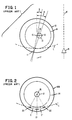
- lens 10 has a small visible circle 11 located at its intended bottom.
- the circle is drilled part way through the lens and is easy to see in the bright light of a slit lamp.
- the eyecare practitioner places a trial lens on the eye of the wearer and, with a slit lamp, projects a narrow beam of light across the center 12 of the patient's pupil 13 and dot 11.
- the angle formed by the narrow light beam and the vertical 17 is considered to be the rotation of the lens.
- this method of measuring rotation has several disadvantages:
- FIG. 2 A second prior method for measuring lens rotation is shown in Fig. 2.
- lens 10A has three line segments 20, 21 and 22, the extensions of which would pass through center 15 of the lens. Segments 20, 21 and 22 are located such that the angles C and C′ formed by the extensions of segments 20 and 21 and of segments 21 and 22 are 30°.
- the line segments are etched into the lens with a laser.
- the practitioner uses a slit lamp to form a narrow beam of light from the center of pupil 13 to middle segment 21.
- the angle formed by this beam and the vertical is used as the amount of rotation.
- the practitioner can estimate the amount of rotation based on his knowledge that the segment are 30° apart.
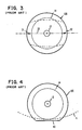
- Fig. 3 illustrates a third prior method for measuring rotation.
- Lens 10B of Fig. 3 has two horizontal line segments 31 and 32 located on a horizontal equator 33 of the lens. Line segments 31 and 32 are very lightly etched onto the lens.
- the practitioner focuses the beam of a slit lamp along line segments 31 and 32.
- the beam also enters the patient's eye through pupil (13).
- the angle formed by the beam and the horizontal is the amount of lens rotation.
- Fig. 4 shows a fourth prior method for measuring lens rotation.
- the lens 10C is truncated so that it has a flat, or nearly flat bottom 40.
- the practitioner focuses a slit lamp beam along truncation 40.
- the angle formed by the beam and the horizontal is the amount of rotation.
- French Patent No. 1,552,106 discloses a lens having several horizontal lines intended for use in measuring the vertical displacement of a lens for optimum placement of near and far vision segments of a bifocal lens. However the patent discloses nothing about how one would measure the rotation of a lens having a toric prescription.
- a first aspect of the invention may be summarized as follows: a contact lens intended to be maintained in a desired angular orientation on a patient's eye comprising:
- a preferred aspect of the invention is as above described and further comprises a pupil section within said corneal section intended to cover the pupil of the patient, and a fourth visible line segment located, perpendicular to said axis initially intended to be located vertically, said fourth line segment being located within the corneal section, such that said fourth line segment and its extensions are outside of the pupil section of said lens.
- the line segments are pigmented and/or the lens is a hydrophilic lens further comprising a scleral section surrounding the corneal section and/or the lens further comprises an asymmetric prescription located over at least a position of said corneal section.
- the pigmented lines make it very easy for the patient to distinguish the bottom of the lens from the top, thereby substantially eliminating upside-down insertion.
- the invention also comprises methods for measuring rotation using the inventive lenses.
- the first aspect of the invention is illustrated in Fig. 6.
- the lens 60 has the usual aspects of prior art lenses, ie. a corneal section 14', vertical axis 17, and a shape intended to maintain the lens's orientation.
- the lens may have an asymmetric prescription over at least the patient's pupil 13.
- the lens has three visible radial line segments 61, 62 and 63 located in corneal section 14'.
- Line segments 61, 62 and 63 are preferably pigmented.
- a first radial line segment 62 is located on vertical axis 17.
- Second and third radial line segments 61 and 63 are located on either side of first line segment 62 such that their extensions, shown dotted, would pass through geometrical centre 15' of corneal section 14' forming two 20° angles D and E.
- the practitioner focuses a slit lamp beam over segment 62 and the centre 15' of the pupil 13 and uses the angle formed by the beam and the true vertical as the measure of rotation.
- Using the lens of Fig. 6 to measure rotation has some of the disadvantages of using the lens of Fig. 2 in that the slit lamp's beam must pass through the patient's pupil and decentralization of the pupil or lens can introduce inaccuracies.
- the potential inaccuracy introduced by pulling the lower lid away is avoided because the line segments are located on the corneal section of the lens.
- use of pigmented line segments renders them easier to see.
- Lens 70 has the usual elements of conventional asymmetric contact lenses.
- a corneal section 14' is intended to cover the wearer's cornea when the lens is worn.
- a pupil section intended to cover the wearer's pupil 13. If the lens is hydrophilic, it will have an outer or scleral section 51 surrounding corneal section 14'.
- An imaginary vertical axis 17 has a top 17' which is intended to be located at the top of the wearer's eye and a bottom 17'' intended to be located at the bottom of the wearer's eye.
- the lens has a shape adapted to maintain the lens at its intended orientation.
- the bottom of the lens is relatively thicker than the top, as shown schematically in Fig.
- the lens of Fig. 7 also has visible horizontal line segment 52.
- the rotation of the lens is the angle formed between vertical axis 17 and the true vertical axis of the wearer's eye, not shown.
- Line segment 52 is located within corneal section 14', perpendicular to vertical axis 17, such that the line segment 52 and its extensions are outside of the pupil section of the lens.
- segment 52 is below the patient's pupil 13, as shown in the drawing.
- line segments 52,61,62, and 63 be pigmented, ie. be formed of an ink, paint, or other material containing pigment.
- Methods for depositing a pigmented marking on the surface of a lens are disclosed in Loshaek's U.S. Patent No. 4,668,240. Briefly, in a preferred method, a contact lens constructed of polymer having functional groups selected from at least one of -COOH, -OH AND -NH-R, wherein R is hydrogen or C1 to C8 alkyl is provided.
- Conventional hydrophilic lenses constructed at least partially of poly(hydroxyethyl methacrylate), which have the functional groups -OH may, for example, be used.
- An ink comprising pigment, binding polymer having functional groups selected from -COOH, -OH or -NH-R and an additional compound having at least two groups per molecule of -NCO or epoxy, is prepared.
- Horizontal line 52 is stamped on the lens using the ink and the ink is cured, e.g. by heat.
- other methods of placing line segment 52 on the lens are possible, e.g. by cutting the line segment into the lens with a laser or by lightly abrasive etching.
- cut lines are not as easy to see as pigmented lines.
- cut or etched line segments have the potential to attract deposits; hence pigmented line segments are highly preferred.
- this paragraph applies to all other visible line segments of this invention.
- the practitioner disposes the lens on the eye of the patient and, with the patient's head in a vertical position, projects a narrow beam of light onto segment 52.
- the angle formed by the light beam and the true horizontal of the patient's eye is the amount of rotation of the lens.
- a lens having the same diameter and rear curve as lens 52 is provided and the patient's assymetric prescription is lathe cut, molded, or spun cast into the lens, taking into account the amount of rotation.
- This new lens also has segments 52,61,62 and 63 on it so that:
- the lens used to initially measure rotation contains a prescription that is approximately equal to that of the patient's prescription.
- the lens used to initially measure rotation will preferably have an assymetric prescription located over at least a portion of its corneal section.
- the lens that is finally dispensed to the patient also has such a prescription.
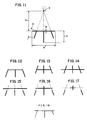
- Fig. 11 illustrates the preferred dimensions for visible line segments in accordance with the invention, which are as follows: 90 - length of horizontal line segment, preferably from 1.5 to 5mm, more preferably about 3.5mm; 91 - length of centre radial line segment, preferably from 05. to 3.5mm, more preferably about 1.67mm; 92 - length of outside radial line seg,emts, preferably from 0.3 to 3.0mm, more preferably about 1mm; 93 - distance from geometric centre of lens 15' to horizontal line segment, preferably from 0 to 6mm, more preferably from 3.5 to 6mm, and most preferably about 4.2mm.
- Distance 93 will normally be greater than zero. However, even if the horizontal line segment is on geometric center 15', i.e., even if distance 93 is zero, the lens still can be used for measuring rotation in test lenses.
- Figures 12 to 17 illustrate some alternative embodiments of the invention of Fig. 7.
- the horizontal segment does not extend beyond the radial line segments.
- one of the outside radial line segments i.e., one of the segments that is not located on the vertical axis, is shorter than the other outside line segment. This allows the patient to determine when the lens has been inadvertantly turned inside out. For example, if the patient knows that the short line segment belongs on the right hand side of the lens, if the short segment is on the left hand side, the patient will know that the lens is inside out.
- the present invention provides a method and lenses for measuring the rotation of a lens that, in its preferred embodiments, overcomes all of the disadvantages of the prior art.
Landscapes
- Health & Medical Sciences (AREA)
- Ophthalmology & Optometry (AREA)
- Physics & Mathematics (AREA)
- General Health & Medical Sciences (AREA)
- General Physics & Mathematics (AREA)
- Optics & Photonics (AREA)
- Eyeglasses (AREA)
- Eye Examination Apparatus (AREA)
- Testing Of Optical Devices Or Fibers (AREA)
Claims (7)
- Kontaktlinse, dazu bestimmt, in einer bestimmten Winkelausrichtung auf einem Auge eines Patienten gehalten zu werden, mit:A. einem Kornealbereich (14') zum Bedecken der Hornhaut des Patienten;B. einer Achse (17), die beim Tragen der Linse und in vertikaler Position des Kopfes des Patienten zunächst vertikal verläuft, so daß das obere Ende am oberen Ende des Auges des Patienten und das untere Ende am unteren Ende des Auges des Patienten liegt;C. einer Formgebung, die zum Halten der Linse in ihrer gewünschten Winkelausrichtung geeignet ist; undD. drei sichtbaren radialen Liniensegmenten (61, 62, 63), die derart angeordnet sind, daß ihre Verlängerungen durch den geometrischen Mittelpunkt des Kornealbereichs verlaufen, wobei das mittlere der radialen Liniensegmente auf der Achse (17) liegt, die zunächst vertikal verläuft;dadurch gekennzeichnet, daß(1) die radialen Liniensegmente in dem Kornealbereich angeordnet sind, und(2) die radialen Liniensegmente (61, 62, 63) und deren Verlängerungen durch den geometrischen Mittelpunkt des Kornealbereichs zwei 20°-Winkel bilden.
- Linse nach Anspruch 1, ferner mit einem in dem Kornealbereich befindlichen Pupillenbereich zum Bedecken der Pupille (13) des Patienten und einem vierten sichtbaren Liniensegment (52), das senkrecht zu der zunächst vertikal verlaufenden Achse (17) verläuft, wobei das vierte Liniensegment ferner innerhalb des Kornealbereichs derart angeordnet ist, daß sich das vierte Liniensegment und dessen Verlängerungen außerhalb des Pupillenbereichs der Linse befinden.
- Linse nach Anspruch 1 oder 2, mit einer torischen Ausbildung über wenigstens einen Teil des Kornealbereichs (14').
- Verfahren zum Schätzen der Winkelverschiebung einer Kontaktlinse in bezug auf ihre ursprüngliche Winkelausrichtung auf dem Auge eines Patienten, mit den folgenden Schritten:A. Anordnen der Linse nach einem der Ansprüche 1 oder 2 auf dem Auge des Patienten; undB. Vergleichen der Positionen der radialen Liniensegmente (61, 62, 63) mit der Vertikalen und Schätzen der Winkelverschiebung der Kontaktlinse in bezug auf ihre ursprüngliche Winkelausrichtung, wobei sich der Kopf des Patienten in vertikaler Position befindet.
- Verfahren zum Messen der Winkelverschiebung einer Kontaktlinse in bezug auf ihre ursprüngliche Winkelausrichtung auf dem Auge eines Patienten, mit den folgenden Schritten:A. Anordnen der Linse nach Anspruch 2 auf dem Auge des Patienten;B. Projizieren eines schmalen Lichtstrahls auf das vierte Liniensegment (52); undC. Messen des zwischen dem schmalen Strahl und einer wahren Horizontallinie gebildeten Winkels, wobei sich der Kopf des Patienten in vertikaler Position befindet.
- Linse nach einem der Ansprüche 1 bis 3, bei der die Liniensegmente pigmentiert sind.
- Linse nach einem der Ansprüche 1 bis 3, oder 6, die hydrophil ist und ferner einen den Kornealbereich umgebenden Skleralbereich (51) aufweist.
Applications Claiming Priority (2)
| Application Number | Priority Date | Filing Date | Title |
|---|---|---|---|
| US203381 | 1988-06-07 | ||
| US07/203,381 US4976533A (en) | 1988-06-07 | 1988-06-07 | Method for measuring the rotation of an assymetric contact lens and lenses for practicing the method |
Publications (2)
| Publication Number | Publication Date |
|---|---|
| EP0346032A1 EP0346032A1 (de) | 1989-12-13 |
| EP0346032B1 true EP0346032B1 (de) | 1994-10-12 |
Family
ID=22753754
Family Applications (2)
| Application Number | Title | Priority Date | Filing Date |
|---|---|---|---|
| EP89305626A Expired - Lifetime EP0346032B1 (de) | 1988-06-07 | 1989-06-05 | Kontaktlinse und Verfahren zum Messen der Rotation mit einer solchen Kontaktlinse |
| EP89906888A Pending EP0426690A1 (de) | 1988-06-07 | 1989-06-05 | Verfahren zum messen der rotation einer asymmetrischen kontaktlinse |
Family Applications After (1)
| Application Number | Title | Priority Date | Filing Date |
|---|---|---|---|
| EP89906888A Pending EP0426690A1 (de) | 1988-06-07 | 1989-06-05 | Verfahren zum messen der rotation einer asymmetrischen kontaktlinse |
Country Status (20)
| Country | Link |
|---|---|
| US (1) | US4976533A (de) |
| EP (2) | EP0346032B1 (de) |
| JP (1) | JP2685319B2 (de) |
| KR (1) | KR930003810B1 (de) |
| AR (1) | AR244890A1 (de) |
| AT (1) | ATE112863T1 (de) |
| AU (1) | AU620886B2 (de) |
| CA (1) | CA1317802C (de) |
| DE (1) | DE68918762T2 (de) |
| DK (1) | DK288990A (de) |
| ES (1) | ES2060768T3 (de) |
| FI (1) | FI906015A0 (de) |
| HK (1) | HK1007444A1 (de) |
| IL (1) | IL90538A (de) |
| MX (1) | MX164108B (de) |
| NZ (1) | NZ229420A (de) |
| PH (1) | PH26412A (de) |
| TR (1) | TR23729A (de) |
| WO (1) | WO1989012246A1 (de) |
| ZA (1) | ZA894257B (de) |
Families Citing this family (27)
| Publication number | Priority date | Publication date | Assignee | Title |
|---|---|---|---|---|
| US5062701A (en) * | 1988-06-07 | 1991-11-05 | Wesley-Jessen Corporation | Asymmetric contact lens |
| DE4012478A1 (de) * | 1990-04-19 | 1991-10-24 | Heinrich Woehlk Inst Fuer Cont | Kontaktlinse mit lagestabilisierung |
| ATE225524T1 (de) * | 1991-06-17 | 2002-10-15 | Dugmont Pty Ltd | Torische kontaktlinse |
| EP0597994A4 (en) * | 1991-08-09 | 1994-09-14 | Capricornia Contact Lens | Toric lens with axis mislocation latitude. |
| CA2100092A1 (en) * | 1991-11-08 | 1993-05-09 | Gunilla Lofgren Nisser | Auxiliary means provided for treatment of visual and/or brain disorder |
| US5184405A (en) * | 1991-12-18 | 1993-02-09 | Jonathan Cress | Method and device for fitting toric contact lenses |
| US5495305A (en) * | 1994-10-27 | 1996-02-27 | Bloom & Kreten | Method for simulation of visual disabilities |
| US5724120A (en) * | 1995-10-02 | 1998-03-03 | Svochak; Jan B. | Multifocal contact lens and method and apparatus for making the same |
| BR9714224A (pt) * | 1996-12-20 | 2000-04-18 | Bausch & Lomb | Marcações de lentes de contato tóricas |
| ID20540A (id) * | 1997-04-07 | 1999-01-07 | Bausch & Lomb | Metoda untuyk mengidentifikasikan ciri-ciri dari lensa kontak |
| DE19726888A1 (de) * | 1997-06-25 | 1999-01-07 | Woehlk Contact Linsen Gmbh | Anpaßverfahren für eine Kontaktlinse und Meßlinse zur Durchführung des Verfahrens |
| US5963299A (en) * | 1997-07-22 | 1999-10-05 | Reyburn; Thomas P. | Method and apparatus for measuring toric contact lens rotation |
| AR013512A1 (es) | 1997-09-24 | 2000-12-27 | Novartis Ag | Metodo para fabricar una lente de contacto astigmatica |
| US5936704A (en) | 1997-12-22 | 1999-08-10 | Gabrielian; Grant | Marked contact lens bearing optical marking element |
| US6024448A (en) * | 1998-03-31 | 2000-02-15 | Johnson & Johnson Vision Products, Inc. | Contact lenses bearing identifying marks |
| US6203156B1 (en) | 1998-03-31 | 2001-03-20 | Johnson & Johnson Vision Care, Inc. | Contact lenses bearing marks |
| JPH11295669A (ja) * | 1998-04-08 | 1999-10-29 | Menicon Co Ltd | トライアルレンズ |
| US5926252A (en) * | 1998-08-25 | 1999-07-20 | Reyburn; Thomas P. | Ophthalmic instrument that measures rotation of a toric contact lens |
| US6042230A (en) * | 1998-12-14 | 2000-03-28 | Johnson & Johnson Vision Products, Inc. | Markings for contact lenses |
| EP1173790A2 (de) | 1999-03-01 | 2002-01-23 | Boston Innovative Optics, Inc. | Vorrichtung und verfahren zur erhöhung der tiefenschärfe des menschlichen auges |
| DE60124619T2 (de) | 2000-05-25 | 2007-09-20 | Novartis Ag | Kontaktlinse mit gespritzter Inversionsmarkierung |
| US20060001828A1 (en) * | 2004-06-30 | 2006-01-05 | Robert Duggan | Automatic identification symbology suitable for contact lens manufacturing verification |
| US7832858B2 (en) * | 2007-05-11 | 2010-11-16 | Ferrara Daniel C | Contact lens permitting translation |
| WO2013082545A1 (en) | 2011-12-02 | 2013-06-06 | Acufocus, Inc. | Ocular mask having selective spectral transmission |
| HUE029206T2 (en) | 2011-12-31 | 2017-02-28 | Novartis Ag | A method for producing contact lenses containing an identification mark |
| US9204962B2 (en) | 2013-03-13 | 2015-12-08 | Acufocus, Inc. | In situ adjustable optical mask |
| US9427922B2 (en) | 2013-03-14 | 2016-08-30 | Acufocus, Inc. | Process for manufacturing an intraocular lens with an embedded mask |
Family Cites Families (12)
| Publication number | Priority date | Publication date | Assignee | Title |
|---|---|---|---|---|
| DE556932C (de) * | 1929-07-02 | 1932-08-16 | Heinrich Naschold | Verfahren zur Darstellung eines Pflanzenschutzmittels |
| FR1400566A (fr) * | 1964-04-17 | 1965-05-28 | Procédé et dispositif de sélection, d'ajustage et de centrage des lentilles ophtalmiques | |
| US3431327A (en) * | 1964-08-31 | 1969-03-04 | George F Tsuetaki | Method of making a bifocal contact lens with an embedded metal weight |
| US3454332A (en) * | 1966-11-03 | 1969-07-08 | Robert Siegel | Corneal plastic contact lens with colored peripheral zone |
| FR1552106A (de) * | 1967-11-17 | 1969-01-03 | ||
| US4268133A (en) * | 1978-07-14 | 1981-05-19 | Bausch & Lomb Incorporated | Preferential orientation of contact lenses |
| US4309085A (en) * | 1979-07-12 | 1982-01-05 | Morrison Robert J | Method for measuring eye features with a contact lens |
| DE3065034D1 (en) * | 1980-06-12 | 1983-11-03 | Biolens Sa | Contact lens for oriented optical correction |
| JPS57179101A (en) * | 1981-04-27 | 1982-11-04 | Lion Corp | Repellent for bloodsucking vermin |
| US4525044A (en) * | 1983-05-05 | 1985-06-25 | Bauman Robert C | Soft contact lens with surface identification and method of using same |
| JPS60199804A (ja) * | 1984-03-26 | 1985-10-09 | Nippon Kayaku Co Ltd | 有害生物忌避剤 |
| FR2582416A1 (fr) * | 1985-05-24 | 1986-11-28 | Bourgeois Sa | Lentille de contact bifocale |
-
1988
- 1988-06-07 US US07/203,381 patent/US4976533A/en not_active Expired - Lifetime
-
1989
- 1989-04-05 TR TR89/0491A patent/TR23729A/xx unknown
- 1989-06-05 ES ES89305626T patent/ES2060768T3/es not_active Expired - Lifetime
- 1989-06-05 ZA ZA894257A patent/ZA894257B/xx unknown
- 1989-06-05 JP JP1506495A patent/JP2685319B2/ja not_active Expired - Lifetime
- 1989-06-05 AT AT89305626T patent/ATE112863T1/de not_active IP Right Cessation
- 1989-06-05 AU AU37603/89A patent/AU620886B2/en not_active Ceased
- 1989-06-05 WO PCT/US1989/002362 patent/WO1989012246A1/en not_active Ceased
- 1989-06-05 CA CA000601721A patent/CA1317802C/en not_active Expired - Fee Related
- 1989-06-05 DE DE68918762T patent/DE68918762T2/de not_active Expired - Lifetime
- 1989-06-05 IL IL90538A patent/IL90538A/xx not_active IP Right Cessation
- 1989-06-05 EP EP89305626A patent/EP0346032B1/de not_active Expired - Lifetime
- 1989-06-05 EP EP89906888A patent/EP0426690A1/de active Pending
- 1989-06-05 PH PH38745A patent/PH26412A/en unknown
- 1989-06-05 FI FI906015A patent/FI906015A0/fi not_active IP Right Cessation
- 1989-06-05 AR AR89314084A patent/AR244890A1/es active
- 1989-06-06 NZ NZ229420A patent/NZ229420A/en unknown
- 1989-06-06 MX MX16346A patent/MX164108B/es unknown
-
1990
- 1990-02-06 KR KR9070240A patent/KR930003810B1/ko not_active Expired - Fee Related
- 1990-12-05 DK DK288990A patent/DK288990A/da not_active Application Discontinuation
-
1998
- 1998-06-25 HK HK98106608A patent/HK1007444A1/en not_active IP Right Cessation
Also Published As
| Publication number | Publication date |
|---|---|
| ATE112863T1 (de) | 1994-10-15 |
| FI906015A7 (fi) | 1990-12-05 |
| JPH03502740A (ja) | 1991-06-20 |
| EP0426690A1 (de) | 1991-05-15 |
| ZA894257B (en) | 1990-02-28 |
| AU3760389A (en) | 1990-01-05 |
| EP0346032A1 (de) | 1989-12-13 |
| DK288990D0 (da) | 1990-12-05 |
| MX164108B (es) | 1992-07-16 |
| DE68918762T2 (de) | 1995-02-16 |
| WO1989012246A1 (en) | 1989-12-14 |
| KR930003810B1 (en) | 1993-05-13 |
| HK1007444A1 (en) | 1999-04-09 |
| IL90538A0 (en) | 1990-01-18 |
| KR900702399A (ko) | 1990-12-07 |
| ES2060768T3 (es) | 1994-12-01 |
| JP2685319B2 (ja) | 1997-12-03 |
| AR244890A1 (es) | 1993-11-30 |
| TR23729A (tr) | 1990-07-30 |
| NZ229420A (en) | 1992-08-26 |
| PH26412A (en) | 1992-07-02 |
| CA1317802C (en) | 1993-05-18 |
| DE68918762D1 (de) | 1994-11-17 |
| IL90538A (en) | 1992-03-29 |
| DK288990A (da) | 1990-12-05 |
| FI906015A0 (fi) | 1990-12-05 |
| US4976533A (en) | 1990-12-11 |
| AU620886B2 (en) | 1992-02-27 |
Similar Documents
| Publication | Publication Date | Title |
|---|---|---|
| EP0346032B1 (de) | Kontaktlinse und Verfahren zum Messen der Rotation mit einer solchen Kontaktlinse | |
| US5062701A (en) | Asymmetric contact lens | |
| HK1007444B (en) | Contact lens and methods for determining rotation using such contact lens | |
| US6607271B2 (en) | Method for mounting ophthalmic lenses | |
| US4095878A (en) | Soft contact lens with flattened region for automatic orientation | |
| US7996997B2 (en) | Spectacle measuring tool | |
| CA1060198A (en) | Device for making ophthalmic measurements and method | |
| US5635998A (en) | Translating multifocal contact lens | |
| US4208800A (en) | Method for making ophthalmic measurements | |
| US5677751A (en) | Decals for multifocals | |
| KR20030076334A (ko) | 검안용 테스트도구 | |
| US4167067A (en) | Measuring device for mounting corrective lenses in spectacles rims | |
| US20190179174A1 (en) | Eyewear Measuring Systems, Methods and Devices | |
| CN109073915B (zh) | 用于确定镜片放置和对齐的镜片边缘特征 | |
| US4177571A (en) | Ophthalmic device for measuring vertex distance and pantoscopic tilt angle | |
| US7540612B2 (en) | Device and method for determining the height of the middle of the pupil in relation to the lowest part of a pair of eyeglasses | |
| NZ240539A (en) | Asymmetric contact lens: visible line segments in corneal section | |
| GB2240405A (en) | Ophthalmic measures and templates | |
| JP3650300B2 (ja) | 瞳孔位置測定具 | |
| KR940000880Y1 (ko) | 안경테 선정용 기구 | |
| CN1085068A (zh) | 一种测定人眼角膜的方法和一种适于该方法的角膜曲率计 | |
| US20240045229A1 (en) | Method for determining the shape of a nose pad to be part of an ophthalmic lens | |
| JPH0542321Y2 (de) | ||
| JPS6382621A (ja) | デジタル式瞳孔間距離計 |
Legal Events
| Date | Code | Title | Description |
|---|---|---|---|
| PUAI | Public reference made under article 153(3) epc to a published international application that has entered the european phase |
Free format text: ORIGINAL CODE: 0009012 |
|
| AK | Designated contracting states |
Kind code of ref document: A1 Designated state(s): ES GR |
|
| 17P | Request for examination filed |
Effective date: 19900216 |
|
| RBV | Designated contracting states (corrected) |
Designated state(s): AT BE CH DE ES FR GB GR IT LI LU NL SE |
|
| XX | Miscellaneous (additional remarks) |
Free format text: VERBUNDEN MIT 89906888.6/0426690 (EUROPAEISCHE ANMELDENUMMER/VEROEFFENTLICHUNGSNUMMER) DURCH ENTSCHEIDUNG VOM 17.09.91. |
|
| 17Q | First examination report despatched |
Effective date: 19911223 |
|
| GRAA | (expected) grant |
Free format text: ORIGINAL CODE: 0009210 |
|
| AK | Designated contracting states |
Kind code of ref document: B1 Designated state(s): AT BE CH DE ES FR GB GR IT LI LU NL SE |
|
| REF | Corresponds to: |
Ref document number: 112863 Country of ref document: AT Date of ref document: 19941015 Kind code of ref document: T |
|
| XX | Miscellaneous (additional remarks) |
Free format text: VERBUNDEN MIT 89906888.6/0426690 (EUROPAEISCHE ANMELDENUMMER/VEROEFFENTLICHUNGSNUMMER) DURCH ENTSCHEIDUNG VOM 17.09.91. |
|
| REF | Corresponds to: |
Ref document number: 68918762 Country of ref document: DE Date of ref document: 19941117 |
|
| REG | Reference to a national code |
Ref country code: ES Ref legal event code: FG2A Ref document number: 2060768 Country of ref document: ES Kind code of ref document: T3 |
|
| ITF | It: translation for a ep patent filed | ||
| ET | Fr: translation filed | ||
| EAL | Se: european patent in force in sweden |
Ref document number: 89305626.7 |
|
| REG | Reference to a national code |
Ref country code: GR Ref legal event code: FG4A Free format text: 3014573 |
|
| PLBE | No opposition filed within time limit |
Free format text: ORIGINAL CODE: 0009261 |
|
| STAA | Information on the status of an ep patent application or granted ep patent |
Free format text: STATUS: NO OPPOSITION FILED WITHIN TIME LIMIT |
|
| 26N | No opposition filed | ||
| ITPR | It: changes in ownership of a european patent |
Owner name: CESSIONE;WJ ACQUISITION CORP. |
|
| PGFP | Annual fee paid to national office [announced via postgrant information from national office to epo] |
Ref country code: LU Payment date: 19960501 Year of fee payment: 8 |
|
| PGFP | Annual fee paid to national office [announced via postgrant information from national office to epo] |
Ref country code: AT Payment date: 19960521 Year of fee payment: 8 |
|
| PGFP | Annual fee paid to national office [announced via postgrant information from national office to epo] |
Ref country code: GR Payment date: 19960528 Year of fee payment: 8 |
|
| PGFP | Annual fee paid to national office [announced via postgrant information from national office to epo] |
Ref country code: CH Payment date: 19960529 Year of fee payment: 8 |
|
| PG25 | Lapsed in a contracting state [announced via postgrant information from national office to epo] |
Ref country code: AT Effective date: 19970605 Ref country code: LU Free format text: LAPSE BECAUSE OF NON-PAYMENT OF DUE FEES Effective date: 19970605 |
|
| PG25 | Lapsed in a contracting state [announced via postgrant information from national office to epo] |
Ref country code: LI Free format text: LAPSE BECAUSE OF NON-PAYMENT OF DUE FEES Effective date: 19970630 Ref country code: GR Free format text: LAPSE BECAUSE OF NON-PAYMENT OF DUE FEES Effective date: 19970630 Ref country code: CH Free format text: LAPSE BECAUSE OF NON-PAYMENT OF DUE FEES Effective date: 19970630 |
|
| REG | Reference to a national code |
Ref country code: CH Ref legal event code: PL |
|
| REG | Reference to a national code |
Ref country code: GB Ref legal event code: 732E |
|
| REG | Reference to a national code |
Ref country code: FR Ref legal event code: RM Ref country code: FR Ref legal event code: TP Ref country code: FR Ref legal event code: CA Ref country code: FR Ref legal event code: CD |
|
| REG | Reference to a national code |
Ref country code: GB Ref legal event code: IF02 |
|
| NLS | Nl: assignments of ep-patents |
Owner name: W.J. ACQUISITION CORP. |
|
| NLS | Nl: assignments of ep-patents |
Owner name: WESLEY-JESSEN CORPORATION |
|
| PGFP | Annual fee paid to national office [announced via postgrant information from national office to epo] |
Ref country code: BE Payment date: 20030513 Year of fee payment: 15 |
|
| PGFP | Annual fee paid to national office [announced via postgrant information from national office to epo] |
Ref country code: NL Payment date: 20030516 Year of fee payment: 15 |
|
| PGFP | Annual fee paid to national office [announced via postgrant information from national office to epo] |
Ref country code: SE Payment date: 20030520 Year of fee payment: 15 |
|
| PGFP | Annual fee paid to national office [announced via postgrant information from national office to epo] |
Ref country code: ES Payment date: 20030611 Year of fee payment: 15 |
|
| REG | Reference to a national code |
Ref country code: FR Ref legal event code: TP |
|
| REG | Reference to a national code |
Ref country code: ES Ref legal event code: PC2A |
|
| NLS | Nl: assignments of ep-patents |
Owner name: NOVARTIS AG |
|
| PG25 | Lapsed in a contracting state [announced via postgrant information from national office to epo] |
Ref country code: SE Free format text: LAPSE BECAUSE OF NON-PAYMENT OF DUE FEES Effective date: 20040606 |
|
| PG25 | Lapsed in a contracting state [announced via postgrant information from national office to epo] |
Ref country code: ES Free format text: LAPSE BECAUSE OF NON-PAYMENT OF DUE FEES Effective date: 20040607 |
|
| PG25 | Lapsed in a contracting state [announced via postgrant information from national office to epo] |
Ref country code: BE Free format text: LAPSE BECAUSE OF NON-PAYMENT OF DUE FEES Effective date: 20040630 |
|
| BERE | Be: lapsed |
Owner name: *NOVARTIS A.G. Effective date: 20040630 |
|
| PG25 | Lapsed in a contracting state [announced via postgrant information from national office to epo] |
Ref country code: NL Free format text: LAPSE BECAUSE OF NON-PAYMENT OF DUE FEES Effective date: 20050101 |
|
| EUG | Se: european patent has lapsed | ||
| EUG | Se: european patent has lapsed | ||
| NLV4 | Nl: lapsed or anulled due to non-payment of the annual fee |
Effective date: 20050101 |
|
| REG | Reference to a national code |
Ref country code: ES Ref legal event code: FD2A Effective date: 20040607 |
|
| PGFP | Annual fee paid to national office [announced via postgrant information from national office to epo] |
Ref country code: IT Payment date: 20070626 Year of fee payment: 19 |
|
| PGFP | Annual fee paid to national office [announced via postgrant information from national office to epo] |
Ref country code: DE Payment date: 20080612 Year of fee payment: 20 |
|
| PGFP | Annual fee paid to national office [announced via postgrant information from national office to epo] |
Ref country code: GB Payment date: 20080611 Year of fee payment: 20 |
|
| REG | Reference to a national code |
Ref country code: FR Ref legal event code: ST Effective date: 20090228 |
|
| PGFP | Annual fee paid to national office [announced via postgrant information from national office to epo] |
Ref country code: FR Payment date: 20070630 Year of fee payment: 19 |
|
| REG | Reference to a national code |
Ref country code: GB Ref legal event code: PE20 Expiry date: 20090604 |
|
| PG25 | Lapsed in a contracting state [announced via postgrant information from national office to epo] |
Ref country code: IT Free format text: LAPSE BECAUSE OF NON-PAYMENT OF DUE FEES Effective date: 20080605 Ref country code: FR Free format text: LAPSE BECAUSE OF NON-PAYMENT OF DUE FEES Effective date: 20080630 |
|
| PG25 | Lapsed in a contracting state [announced via postgrant information from national office to epo] |
Ref country code: GB Free format text: LAPSE BECAUSE OF EXPIRATION OF PROTECTION Effective date: 20090604 |