EP0345366A1 - Moteur à combustion interne à huit temps ou moteur diesel - Google Patents
Moteur à combustion interne à huit temps ou moteur diesel Download PDFInfo
- Publication number
- EP0345366A1 EP0345366A1 EP88109096A EP88109096A EP0345366A1 EP 0345366 A1 EP0345366 A1 EP 0345366A1 EP 88109096 A EP88109096 A EP 88109096A EP 88109096 A EP88109096 A EP 88109096A EP 0345366 A1 EP0345366 A1 EP 0345366A1
- Authority
- EP
- European Patent Office
- Prior art keywords
- axis
- engine
- internal combustion
- compression ratio
- piston
- Prior art date
- Legal status (The legal status is an assumption and is not a legal conclusion. Google has not performed a legal analysis and makes no representation as to the accuracy of the status listed.)
- Withdrawn
Links
Images


Classifications
-
- F—MECHANICAL ENGINEERING; LIGHTING; HEATING; WEAPONS; BLASTING
- F02—COMBUSTION ENGINES; HOT-GAS OR COMBUSTION-PRODUCT ENGINE PLANTS
- F02D—CONTROLLING COMBUSTION ENGINES
- F02D15/00—Varying compression ratio
- F02D15/04—Varying compression ratio by alteration of volume of compression space without changing piston stroke
-
- F—MECHANICAL ENGINEERING; LIGHTING; HEATING; WEAPONS; BLASTING
- F02—COMBUSTION ENGINES; HOT-GAS OR COMBUSTION-PRODUCT ENGINE PLANTS
- F02B—INTERNAL-COMBUSTION PISTON ENGINES; COMBUSTION ENGINES IN GENERAL
- F02B75/00—Other engines
- F02B75/04—Engines with variable distances between pistons at top dead-centre positions and cylinder heads
- F02B75/047—Engines with variable distances between pistons at top dead-centre positions and cylinder heads by means of variable crankshaft position
-
- F—MECHANICAL ENGINEERING; LIGHTING; HEATING; WEAPONS; BLASTING
- F02—COMBUSTION ENGINES; HOT-GAS OR COMBUSTION-PRODUCT ENGINE PLANTS
- F02B—INTERNAL-COMBUSTION PISTON ENGINES; COMBUSTION ENGINES IN GENERAL
- F02B3/00—Engines characterised by air compression and subsequent fuel addition
- F02B3/06—Engines characterised by air compression and subsequent fuel addition with compression ignition
-
- F—MECHANICAL ENGINEERING; LIGHTING; HEATING; WEAPONS; BLASTING
- F02—COMBUSTION ENGINES; HOT-GAS OR COMBUSTION-PRODUCT ENGINE PLANTS
- F02B—INTERNAL-COMBUSTION PISTON ENGINES; COMBUSTION ENGINES IN GENERAL
- F02B75/00—Other engines
- F02B75/02—Engines characterised by their cycles, e.g. six-stroke
- F02B75/021—Engines characterised by their cycles, e.g. six-stroke having six or more strokes per cycle
Definitions
- the present invention relates to an eight cycle or Diesel type internal combustion carburation engine.
- the present invention relates to an eight cycle or Diesel type internal combustion carburation engine having the important and original feature increase the compression ratio at each engine revolution, each time one of the pistons reaches top dead point or center.
- This graph illustrates the relationship between the engine's compression ratio (Rc) and thermal efficiency (Ni), shown respectively on the horizontal and vertical axes.
- the compression ratio varies from 0 to 20, while the thermal efficiency varies between 0 and 7.
- the curve representing the engine's thermal efficiency as a function of the compression ratio, can be compared to a hyperbolic branch. It, therefore, follows that the thermal efficiency (Ni) increases rapidly at the beginning of the curve, i.e. for relatively low compression ratios, while higher pressures, such as Rc's from 10 to 20, cause the Ni to grow in smaller increments.
- the object of the present invention is to provide an internal combustion engine which works on the principle described above, i.e., the automatic variation of the compression ratio.
- the eight cycle Diesel type internal combustion engine as claimed allows to obtain the above object.
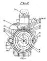
- the intake valve (10) is shown on the cylinder head (3) above the piston (12) (see Figure 1), while the exhaust valve (11) is shown in figure 3 which is a side view of the engine.
- the intake (10) and exhaust (11) valves are driven by a cam shaft (7) which is carried by known supports (8), inside of which it rotates.
- Reference E of figure 1 illustrates the distance between the B axis and the A axis.
- the upper 30 and lower 41 supports of the crankshaft (29) are fixed to and supported by the A axis.
- Such supports (30) and (41) are firmly assembled and connected by clamping screws (49) as shown in figure 1; the left screw is longer than the right one.
- the main feature of the present invention is the staggered position of the A axis of the supports (30) and (41) in relation to the B axis.
- the engine of the present invention is, moreover, equipped with an original mechanism which allows the automatic movement of the top of the piston (12) in order to achieve a desired variation in the compression ratio (Rc).
- FIG. 2 shows that an appropriately shaped plate (16), part of which is toothed (16a) is connected to the supports (30) and (41) of the crankshaft (29).
- the clutch casing (20) is mounted on this plate (16) provided a toothed sector (16a) and rotates around the A axis, while the B axis is its own central axis.
- the clutch (20) and plate (16) rotate eccentrically.
- the clutch casing (20) rotation around the A axis is provided by a gear (55) (see figure 2) driven by a direct current motor (56), through a undirectional reducer (69).
- the engine of the present invention has a fixed casing (15) which houses the above mentioned elements as well as three proximity microswitches (17), (18) and (19). These microswitches work in conjunction with three position detectors (58), (59) and (60), mounted on the clutch casing (20) and caused to cooperate with the microswitches (17), (18) and (19). Insofar as the casing (15) is stationary and the clutch casing (20) is rotating, it is possible to vary the positioning between the three microswitches and the three detectors.
- a minimum compression ratio value exists, being maximum the distance X between the top of the piston 12 and the bottom of the cylinder head (see fig. 5).
- a medium compression ratio value is achieved when microswitch (18) is aligned with position detector (59).
- the maximum compression ratio value is achieved by aligning microswitch (19) with position detector (60); in fact in this position the distance y between the top of the piston (12) and the bottom of the cylinder head is smallest (see fig. 6).
- a suitable computer situated on the board of the motor vehicle determines the appropriate and selected compression ratio values (Rc) on the basis of the following factors: number of engine revolutions; position of the throttle which regulates fuel intake measured by a suitable device (9), and finally, the temperature of the air taken in.
- Rc compression ratio values
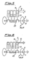
- Figure 4 shows the timing system of the engine of the present invention.
- the engine of the present invention has an additional axis in which a gear (70) with a pulley (71) is located.
- Gear (36) through a chain, provides movement to a gear (70); both of these are in the same horizontal axis whenever a medium compression ratio exists.
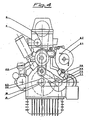
- FIG. 3 illustrates a complete 4-cylinder engine according to the present invention.
- the basic elements of the invention, and other known elements, which are not to be considered innovations, are illustrated.
- Reference 1 indicates the engine block to which the front cover is fixed in the conventional manner.
- Reference 3 indicates the cylinder head, and reference 4 identifies the chain stretching gear.
- Reference 21 marks the engine flywheel, and the clutch is identified by reference 22.
- the clutch control lever is indicated by reference 23, while reference 24 marks the clutch pressure spring bearing.
- the gearbox is indicated by 28, and 35 identifies the pump which sends oil through a flexible pipe numbered 37; the oil pan is indicated by 32.
- the starting motor and related gear shown in figure 2 are indicated by references 63 and 62, respectively.
- the present engine allows the programmed/programable variation of the compression ratio, without varying the amount of fuel mixture consumed, in order to achieve the optimal engine efficiency.
Priority Applications (1)
| Application Number | Priority Date | Filing Date | Title |
|---|---|---|---|
| EP88109096A EP0345366A1 (fr) | 1988-06-08 | 1988-06-08 | Moteur à combustion interne à huit temps ou moteur diesel |
Applications Claiming Priority (1)
| Application Number | Priority Date | Filing Date | Title |
|---|---|---|---|
| EP88109096A EP0345366A1 (fr) | 1988-06-08 | 1988-06-08 | Moteur à combustion interne à huit temps ou moteur diesel |
Publications (1)
| Publication Number | Publication Date |
|---|---|
| EP0345366A1 true EP0345366A1 (fr) | 1989-12-13 |
Family
ID=8199036
Family Applications (1)
| Application Number | Title | Priority Date | Filing Date |
|---|---|---|---|
| EP88109096A Withdrawn EP0345366A1 (fr) | 1988-06-08 | 1988-06-08 | Moteur à combustion interne à huit temps ou moteur diesel |
Country Status (1)
| Country | Link |
|---|---|
| EP (1) | EP0345366A1 (fr) |
Cited By (17)
| Publication number | Priority date | Publication date | Assignee | Title |
|---|---|---|---|---|
| FR2669676A1 (fr) * | 1990-11-23 | 1992-05-29 | Jurkovic Dimitri | Paliers permettant de faire varier le taux de compression d'un moteur a combustion interne. |
| EP0560701A1 (fr) * | 1992-03-13 | 1993-09-15 | MATESIC, Alex | Moteur à combustion interne, avec taux de compression et masse tournante du volant moteur ajustables en marche |
| NL1005395C2 (nl) * | 1997-02-06 | 1998-08-07 | Leon Ruben Van De Werve | Verbrandingsmotor met variabele compressieverhouding. |
| WO1999061766A1 (fr) * | 1998-05-29 | 1999-12-02 | Edward Charles Mendler | Berceau rigide de vilebrequin et actionneur |
| US6260532B1 (en) | 1998-09-28 | 2001-07-17 | Edward Charles Mendler | Rigid crankshaft cradle and actuator |
| EP1228298A1 (fr) * | 1999-11-12 | 2002-08-07 | Edward Charles Mendler | Berceau rigide de vilebrequin et actionneur |
| US6443107B1 (en) | 1999-05-27 | 2002-09-03 | Edward Charles Mendler | Rigid crankshaft cradle and actuator |
| EP1245803A1 (fr) * | 2001-03-30 | 2002-10-02 | Gomecsys B.V. | Moteur à combustion interne à taux de compression variable |
| AT414017B (de) * | 2004-07-08 | 2006-08-15 | Avl List Gmbh | Brennkraftmaschine |
| CN101749114A (zh) * | 2008-11-28 | 2010-06-23 | 现代自动车株式会社 | 用于车辆发动机的可变压缩率装置 |
| DE102009043505A1 (de) | 2009-09-30 | 2011-03-31 | Fev Motorentechnik Gmbh | Verbrennungskraftmaschine mit variabler Verdichtung |
| US8714134B2 (en) | 2008-02-13 | 2014-05-06 | Gomecys B.V. | Reciprocating piston mechanism and a method of increasing internal EGR in an internal combustion engine |
| US20140360292A1 (en) | 2012-01-24 | 2014-12-11 | Joannes Jacobus Josephus SLEPER | Reciprocating piston mechanism |
| US9279363B2 (en) | 2009-07-15 | 2016-03-08 | Gomecsys B.V. | Reciprocating piston mechanism |
| US10145299B2 (en) | 2014-04-08 | 2018-12-04 | Gomecsys B.V. | Internal combustion engine including variable compression ratio |
| US10233966B2 (en) | 2013-11-13 | 2019-03-19 | Gomecsys B.V. | Method of assembling and an assembly of a crankshaft and a crank member |
| US10557409B2 (en) | 2015-10-22 | 2020-02-11 | Gomecsys B.V. | Heat engine comprising a system for varying the compression ratio |
Citations (4)
| Publication number | Priority date | Publication date | Assignee | Title |
|---|---|---|---|---|
| FR692084A (fr) * | 1929-06-03 | 1930-10-30 | Moteur à compression variable | |
| FR913622A (fr) * | 1945-03-20 | 1946-09-16 | Moteur Et Accessoires Aviat Mi | Perfectionnement aux moteurs à auto-allumage |
| DE3004402A1 (de) * | 1980-02-07 | 1981-08-13 | Daimler-Benz Ag, 7000 Stuttgart | Kurbeltrieb einer hubkolben-brennkraftmaschine mit waehrend des betriebes veraenderbarem kompressionsverhaeltnis |
| US4738230A (en) * | 1986-03-13 | 1988-04-19 | Johnson Kenneth A | Variable compression ratio control |
-
1988
- 1988-06-08 EP EP88109096A patent/EP0345366A1/fr not_active Withdrawn
Patent Citations (4)
| Publication number | Priority date | Publication date | Assignee | Title |
|---|---|---|---|---|
| FR692084A (fr) * | 1929-06-03 | 1930-10-30 | Moteur à compression variable | |
| FR913622A (fr) * | 1945-03-20 | 1946-09-16 | Moteur Et Accessoires Aviat Mi | Perfectionnement aux moteurs à auto-allumage |
| DE3004402A1 (de) * | 1980-02-07 | 1981-08-13 | Daimler-Benz Ag, 7000 Stuttgart | Kurbeltrieb einer hubkolben-brennkraftmaschine mit waehrend des betriebes veraenderbarem kompressionsverhaeltnis |
| US4738230A (en) * | 1986-03-13 | 1988-04-19 | Johnson Kenneth A | Variable compression ratio control |
Cited By (21)
| Publication number | Priority date | Publication date | Assignee | Title |
|---|---|---|---|---|
| FR2669676A1 (fr) * | 1990-11-23 | 1992-05-29 | Jurkovic Dimitri | Paliers permettant de faire varier le taux de compression d'un moteur a combustion interne. |
| EP0560701A1 (fr) * | 1992-03-13 | 1993-09-15 | MATESIC, Alex | Moteur à combustion interne, avec taux de compression et masse tournante du volant moteur ajustables en marche |
| NL1005395C2 (nl) * | 1997-02-06 | 1998-08-07 | Leon Ruben Van De Werve | Verbrandingsmotor met variabele compressieverhouding. |
| WO1999061766A1 (fr) * | 1998-05-29 | 1999-12-02 | Edward Charles Mendler | Berceau rigide de vilebrequin et actionneur |
| US6260532B1 (en) | 1998-09-28 | 2001-07-17 | Edward Charles Mendler | Rigid crankshaft cradle and actuator |
| US6443107B1 (en) | 1999-05-27 | 2002-09-03 | Edward Charles Mendler | Rigid crankshaft cradle and actuator |
| EP1228298A4 (fr) * | 1999-11-12 | 2004-03-24 | Edward Charles Mendler | Berceau rigide de vilebrequin et actionneur |
| US6637384B1 (en) | 1999-11-12 | 2003-10-28 | Edward Charles Mendler | Rigid crankshaft cradle and actuator |
| EP1228298A1 (fr) * | 1999-11-12 | 2002-08-07 | Edward Charles Mendler | Berceau rigide de vilebrequin et actionneur |
| WO2002079626A1 (fr) * | 2001-03-30 | 2002-10-10 | Gomecsys B.V. | Moteur a combustion interne a taux de compression variable |
| EP1245803A1 (fr) * | 2001-03-30 | 2002-10-02 | Gomecsys B.V. | Moteur à combustion interne à taux de compression variable |
| AT414017B (de) * | 2004-07-08 | 2006-08-15 | Avl List Gmbh | Brennkraftmaschine |
| US8714134B2 (en) | 2008-02-13 | 2014-05-06 | Gomecys B.V. | Reciprocating piston mechanism and a method of increasing internal EGR in an internal combustion engine |
| CN101749114A (zh) * | 2008-11-28 | 2010-06-23 | 现代自动车株式会社 | 用于车辆发动机的可变压缩率装置 |
| US9279363B2 (en) | 2009-07-15 | 2016-03-08 | Gomecsys B.V. | Reciprocating piston mechanism |
| DE102009043505A1 (de) | 2009-09-30 | 2011-03-31 | Fev Motorentechnik Gmbh | Verbrennungskraftmaschine mit variabler Verdichtung |
| US20140360292A1 (en) | 2012-01-24 | 2014-12-11 | Joannes Jacobus Josephus SLEPER | Reciprocating piston mechanism |
| US10234006B2 (en) | 2012-01-24 | 2019-03-19 | Gomecsys B.V. | Reciprocating piston mechanism |
| US10233966B2 (en) | 2013-11-13 | 2019-03-19 | Gomecsys B.V. | Method of assembling and an assembly of a crankshaft and a crank member |
| US10145299B2 (en) | 2014-04-08 | 2018-12-04 | Gomecsys B.V. | Internal combustion engine including variable compression ratio |
| US10557409B2 (en) | 2015-10-22 | 2020-02-11 | Gomecsys B.V. | Heat engine comprising a system for varying the compression ratio |
Similar Documents
| Publication | Publication Date | Title |
|---|---|---|
| EP0345366A1 (fr) | Moteur à combustion interne à huit temps ou moteur diesel | |
| US6230671B1 (en) | Variable compression and asymmetrical stroke internal combustion engine | |
| CN1074083C (zh) | 具有对置活塞的内燃机 | |
| US20140137824A1 (en) | Engine assembly with phasing mechanism on eccentric shaft for variable cycle engine | |
| US4608951A (en) | Reciprocating piston engine | |
| KR20090104498A (ko) | 가변 압축비 장치 | |
| EP1347160B1 (fr) | Moteur à combustion avec taux de compression variable | |
| WO1991014860A1 (fr) | Moteur a explosion a taux de compression variable et regule | |
| EP1421256A1 (fr) | Moteur alternatif a combustion interne ameliore | |
| WO2006007259A2 (fr) | Moteur a turbocombustion | |
| US10267225B2 (en) | Internal combustion engine | |
| JP5478741B2 (ja) | 低燃費低エミッション2ストロークエンジン | |
| US6167851B1 (en) | Movable crankpin, variable compression-ratio, piston engine | |
| CN1437678A (zh) | 内燃机 | |
| CN101205812A (zh) | 四活塞缸体旋转发动机 | |
| US4363295A (en) | Movable head engine | |
| US2839036A (en) | Rotary valve timing mechanism | |
| US11274552B2 (en) | Engine crank and connecting rod mechanism | |
| WO2010151238A1 (fr) | Système de soupape rotative pour moteur à combustion interne | |
| EP0434646A1 (fr) | Système pour varier le point mort maximum d'un moteur à combustion interne | |
| WO2015088347A1 (fr) | Moteur à combustion comprenant un cylindre | |
| CN85103216A (zh) | 活塞齿条式内燃机 | |
| CN103233789A (zh) | 应用二冲程阿特金森循环的多模全顶置气门二冲程内燃机 | |
| RU2053392C1 (ru) | Двигатель внутреннего сгорания | |
| AU610054B2 (en) | Rotating cylinder engine |
Legal Events
| Date | Code | Title | Description |
|---|---|---|---|
| PUAI | Public reference made under article 153(3) epc to a published international application that has entered the european phase |
Free format text: ORIGINAL CODE: 0009012 |
|
| AK | Designated contracting states |
Kind code of ref document: A1 Designated state(s): DE ES FR |
|
| 17P | Request for examination filed |
Effective date: 19900214 |
|
| 17Q | First examination report despatched |
Effective date: 19910115 |
|
| STAA | Information on the status of an ep patent application or granted ep patent |
Free format text: STATUS: THE APPLICATION IS DEEMED TO BE WITHDRAWN |
|
| 18D | Application deemed to be withdrawn |
Effective date: 19910528 |